Panasonic MINAS A5 Series Operating Instructions Manual
Ac servo motor & driver
Hide thumbs
Also See for MINAS A5 Series:
- Operating instructions manual (31 pages) ,
- Quick start manual (19 pages)
Table of Contents
Advertisement
Operating Instructions (Overall)
AC Servo Motor & Driver
MINAS A5-series
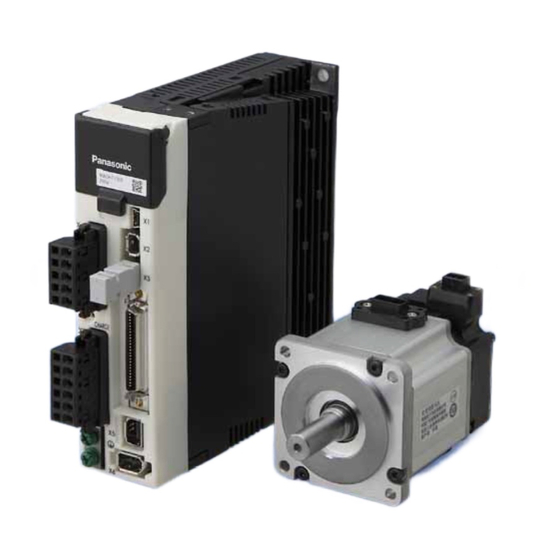
* This product image is 200W type of A5-series.
Thank you for purchasing this Panasonic product.
Before operating this product, please read the instructions carefully, and save this manual for future use.
Phone: 800.894.0412 - Fax: 888.723.4773 - Web: www.clrwtr.com - Email: info@clrwtr.com
Advertisement
Chapters
Table of Contents

Related Manuals for Panasonic MINAS A5 Series


Summary of Contents for Panasonic MINAS A5 Series
- Page 1 MINAS A5-series * This product image is 200W type of A5-series. Thank you for purchasing this Panasonic product. Before operating this product, please read the instructions carefully, and save this manual for future use. Phone: 800.894.0412 - Fax: 888.723.4773 - Web: www.clrwtr.com - Email: info@clrwtr.com...
- Page 2 Thank you for purchasing Digital AC Servo Motor & Driver, MINAS A5-series. This instruction manual contains information necessary to correctly and safely use the MINAS A5-series motor and driver. By reading this instruction manual, you will learn how to identify the model of the motor and driver that will be best suitable your application, how to wire and set up them, how to set parameters, and how to locate possible cause of symptom and to take corrective action.
- Page 3 Organization of this manual Before Using the Products Check of the Driver Model ... Installation Describes how to identify and select the desired product and components, how to Preparation Operating requirements and procedure Shows the timing chart and the list of parameters, and describes how to make wiring and to use the front panel.
-
Page 4: Table Of Contents
Contents page .................... 3 Organization of this manual ......................6 Safety Precautions ..............10 Conformance to international standards ..................11 Maintenance and Inspections 1. Before Using the Products ..............1-1 1. Introduction .......................1-2 2. Driver ........................1-3 3. Motor ........................1-21 4. - Page 5 page 4. Setup ........................4-1 1. Describes parameters ....................4-2 2. JOG running ......................4-59 5. Adjustment ......................5-1 1. Gain Adjustment ......................5-2 2. Real-Time Auto-Gain Tuning ..................5-4 3. Adaptive Filter ......................5-10 4. Manual Auto-Gain Tuning (Basic) ................5-13 5.
- Page 6 Safety Precautions Please observe safety precautions fully. The following explanations are for things that must be observed in order to prevent harm to people and damage to property. degree of potential harm or damage. Danger Indicates great possibility of death or serious injury. Caution Indicates the possibility of injury or property damage.
- Page 7 In the case of the motor with shaft end keyway, do not touch the keyway with bare hands. Failure to observe this instruc- Do not touch the rotating portion of the motor tion could result in personal while it is running. injury.
- Page 8 Safety Precautions Please observe safety precautions fully. Caution Failure to observe this instruc- Do not hold the motor cable or motor shaft during tion could result in injuries. the transportation. Failure to observe this instruc- Don't drop or cause topple over of something dur- tion could result in injuries and ing transportation or installation.
- Page 9 Make an appropriate mounting of the Product matching to its wight and output rating. ments will result in personal injury or malfunction. rection. Using it for transportation of the Use the eye bolt of the motor for transportation of machine will cause personal the motor only, and never use this for transporta- injury or malfunction.
- Page 10 CSA : Canadian Standards Association Pursuant to the directive 2004/108/EC, article 9(2) Panasonic Testing Centre Panasonic Service Europe, a division of Panasonic Marketing Europe GmbH Winsbergring 15, 22525 Hamburg, F.R. Germany * Products shall conform to the statutory regulations applied in the place of destination.
- Page 11 Maintenance and Inspections Routine maintenance and inspection of the driver and motor are essential for the proper and safe operation. Notes on Maintenance and Inspection 1) Turn on and turn off should be done by operators or inspectors themselves. When es- tablishing a system using safety functions, completely understand the applicable safety standards and the operating instruction manual or technical documents for the product.
- Page 12 Maintenance and Inspections Guideline for Parts Replacement Use the table below for a reference. Parts replacement cycle varies depending on the ac- tual operating conditions. Defective parts should be replaced or repaired when any error have occurred. Disassembling for inspection and repair should be carried out only by authorized dealers or service Prohibited company.
-
Page 13: Before Using The Products
. Before Using the Products 1. Introduction Outline ......................1-2 On Opening the Product Package ...............1-2 2. Driver Check of the Model..................1-3 Parts Description A to E-frame....................1-4 F-frame .....................1-5 G-frame.....................1-6 H-frame.....................1-7 D to F-frame (400 V).................1-8 G-frame (400 V)..................1-9 H-frame (400 V) ..................1-10 Specifications.....................1-11 Block Diagram ...................1-15 3. -
Page 14: Introduction
1. Introduction Before Using Outline the Products The AC Servo Motor & Driver, MINAS A5-series is the latest servo system that meets all Compared with the preceding A4-series, product of A5-series offers superior performance Newly designed motors have wide range of outputs from 50 W to 15.0 kW, associated (Only for position control type have range of outputs from 50 W to 5.0 kW.) They are compatible with 2 closed controls (serial communication type and A-/B-phase output type) and provided with various automatic adjusting functions such as real time... -
Page 15: Driver Check Of The Model
2. Driver Before Using Check of the Model the Products Contents of Name Plate Model number Serial Number e.g.) : P09 04 0001N Input/output voltage Lot number Number of phase Month of production Rated input/output current Year of production (Lower 2 digits of AD year) Input/output frequency Rated output of Manufacture date... -
Page 16: Parts Description
2. Driver Before Using Parts Description the Products A to D-frame Front panel Connector XA: Connector X7: Monitor connector for main power connection 05JFAT-SAXGF (JST) Connector X1: USB connector Main power Connector X2: for Serial bus input terminals Connector X3: Safety function connector Control power input terminals Connector X4: Parallel I/O connector... -
Page 17: F-Frame
2. Driver Parts Description F-frame Details of terminal block Front panel Connector X7: Monitor connector Connector X1: USB connector Main power Connector X2: for Serial bus input terminals Connector X3: Safety function connector Control power input terminals Connector X4: Parallel I/O connector Terminals for external regenerative resistor Connector X5:... -
Page 18: G-Frame
2. Driver Parts Description G-frame Front panel Terminal cover Connector X7: Monitor connector screw Connector X1: USB connector Connector X2: for Serial bus L 2C Connector X3: Safety function connector Terminal cover Connector X4: Parallel I/O connector Connector X5: for feedback scale connection Connector X6: for encoder connection Terminal cover... -
Page 19: H-Frame
2. Driver Parts Description H-frame Front panel Connector X7: Monitor connector Connector X1: USB connector Connector X2: for Serial bus Connector X3: Safety function connector Connector X4: Parallel I/O connector Connector X5: for feedback scale connection Connector X6: for encoder connection CHARGE Charge lamp Screws for earth (x2) - Page 20 2. Driver Parts Description D, E-frame (400 V) Connector XA: for main power connection Front panel 03JFAT-SAYGSA-L (JST) Connector XD: Connector X7: Monitor connector Control power input terminals 02MJFAT-SAGF (JST) Connector X1: USB connector Control power Connector X2: for Serial bus input terminals Main power Connector X3: Safety function connector...
-
Page 21: G-Frame (400 V)
2. Driver Parts Description G-frame (400 V) Front panel Terminal cover Connector X7: Monitor connector screw Connector X1: USB connector Connector X2: for Serial bus Connector X3: Safety function connector Terminal cover Connector X4: Parallel I/O connector Connector X5: for feedback scale connection Connector X6: for encoder connection Terminal cover... -
Page 22: H-Frame (400 V)
2. Driver Parts Description H-frame (400 V) H-frame (400 V) Front panel Connector X7: Monitor connector Connector X1: USB connector Connector X2: for Serial bus Connector X3: Safety function connector Connector X4: Parallel I/O connector Connector X5: for feedback scale connection Connector X6: for encoder connection CHARGE Charge lamp... -
Page 23: Specifications
2. Driver Before Using Specifications the Products (Velocity, position, torque, full-closed control type) +10% Main circuit Single phase, 100 to 120V 50/60Hz –15% 100V +10% Control circuit Single phase, 100 to 120V 50/60Hz –15% +10% A to Single/3-phase, 200 to 240V 50/60Hz D-frame –15%... -
Page 24: Setup
2. Driver Specifications (Velocity, position, torque, full-closed control type) (1) Servo-ON input (2) Alarm clear input (3) Gain switching input Control input (4) Positive direction over-travel inhibition input (5) Negative direction over-travel inhibition input (6) Forced alarm input (7) Inertia ratio switching input (1) Servo-Alarm output (2) Servo-Ready output (3) External brake release signal Control output (6) Zero-speed detection output signal (7) Alarm output (8) Alarm attribute output... - Page 25 2. Driver Before Using Specifications the Products (Only for position control type) +10% Main circuit Single phase, 100 to 120V 50/60Hz –15% 100V +10% Control circuit Single phase, 100 to 120V 50/60Hz –15% +10% A to Single/3-phase, 200 to 240V 50/60Hz D-frame –15%...
- Page 26 2. Driver Specifications (Only for position control type) (1) Deviation counter clear (2) Command pulse inhibition Control input (3) Command dividing gradual increase switching (4) Damping control switching etc. Control output Positioning complete (In-position) etc. Max. command Exclusive interface for Photo-coupler: 500kpps Exclusive interface for line driver : 4Mpps Differential input Input pulse signal...
-
Page 27: Block Diagram
2. Driver Before Using Block Diagram the Products A, B-frame (100/200 V) Fuse Resistor Fuse Voltage detection Fuse Gate drive DC/DC PS for gate drive PS for RE Front panel Error Sequence control detection Display Protective operation Parameter control EEPROM curcuit control Serial... - Page 28 2. Driver Block Diagram E-frame (200 V) Fuse Resistor Fuse Voltage detection Gate drive Fuse DC/DC PS for gate drive PS for RE Front panel Error Sequence control detection Display Protective operation Parameter control EEPROM curcuit control Serial Safety function Alarm signal Position...
- Page 29 2. Driver Block Diagram G-frame (200 V) Fuse Resistor Fuse Voltage detection Gate drive Fuse DC/DC PS for gate drive PS for RE Front panel Error Sequence control detection Display Protective operation Parameter control EEPROM curcuit control Serial Safety function Alarm signal Pulse train...
- Page 30 2. Driver Block Diagram D-frame (400 V) Fuse Resistor Fuse Voltage detection Fuse ±12V Gate drive DC/DC PS for gate drive PS for RE Front panel Error Sequence control detection Display Protective operation Parameter control EEPROM curcuit control Serial Safety function Alarm signal Pulse train...
- Page 31 2. Driver Block Diagram F-frame (400 V) Fuse Resistor Fuse Voltage detection Fuse ±12V Gate drive DC/DC PS for gate drive PS for RE Front panel Error Sequence control detection Display Protective operation Parameter control EEPROM curcuit control Serial Safety function Alarm signal Position...
- Page 32 2. Driver Block Diagram H-frame (400 V) Fuse Resistor Fuse Voltage detection Gate drive Fuse DC/DC PS for gate drive PS for RE Front panel Error Sequence control detection Display Protective operation Parameter control EEPROM curcuit control Serial Safety function Alarm signal Position...
-
Page 33: Motor
3. Motor Before Using Check of the Model the Products Contents of Name Plate Serial Number Model e.g.) : 09 04 0001N Rated input voltage/current Lot number Month of production Rated output Year of production (Lower 2 digits of AD year) Rated frequency Manufacture date e.g.) : 2009 04 01... -
Page 34: Parts Description
3. Motor Before Using Parts Description the Products Connector for encoder Connector for motor Flange Motor frame Mounting holes (X4) [with Brake] Connector for encoder Connector for brake Connector for motor Flange Motor frame Mounting holes (X4) e.g.) : Low inertia type (MSME series, 50W) MSME 750W(400V), 1.0kW to 5.0kW MDME... -
Page 35: Check Of The Combination Of The Driver And The Motor
4. Check of the Combination of the Driver and the Motor Before Using Incremental Specifications, 20-bit the Products Remarks Do not use in other combinations than those listed below. Motor Driver Rated Model of velocity, Model of Only for Power Rated Type rotational... - Page 36 4. Check of the Combination of the Driver and the Motor Incremental Specifications, 20-bit Motor Driver Rated Model of velocity, Model of Only for Power Rated Type rotational Model position, torque and position control Frame supply output speed full-closed control type type Single/ 3-phase,...
-
Page 37: Absolute Specifications, 17-Bit
4. Check of the Combination of the Driver and the Motor Before Using Absolute Specifications, 17-bit the Products Remarks Do not use in other combinations than those listed below. Motor Driver Model of velocity, Power Rated rotational Rated Type Model position, torque and Frame supply... - Page 38 4. Check of the Combination of the Driver and the Motor Absolute Specifications, 17-bit Motor Driver Model of velocity, Power Rated rotational Rated Type Model position, torque and Frame supply speed output full-closed control type Single/3-phase, MFME152S1 * 1.5kW MDDHT5540 D-frame 200V MFME252S1 *...
-
Page 39: Junction Cable For Motor
4. Check of the Combination of the Driver and the Motor Before Using Junction cable for motor the Products Encoder cable Detail Note)1 Note)1 Motor series Absolute Specifications, 17-bit page MSMD 50W to 750W MFECA0 ** 0EAM — 7-98 MFECA0 0MJD MFECA0 0MJE... -
Page 40: Installation
5. Installation Before Using Driver the Products Install the driver properly to avoid a breakdown or an accident. Installation Place 1) Install the driver in a control panel enclosed in noncombustible material and placed in- door where the product is not subjected to rain or direct sunlight. The products are not waterproof. - Page 41 5. Installation Driver Mounting Direction and Spacing (On the H-frame, the cooling fan is also installed on the upper side.) Observe the environmental conditions of the control panel described in the previous page. Control panel 100mm or more 40mm 40mm more more ...
- Page 42 5. Installation Driver Be sure to conduct wiring properly and securely. Insecure or improper wiring may cause the mo- tor running out of control or being damaged from overheating. In addition, pay attention not to al- low conductive materials, such as wire chips, entering the driver during the installation and wiring. cation.
- Page 43 5. Installation Driver Relationship between Wire Diameter and Permissible Current Example: Power supply 3-phase, 200 V, 35 A, ambient temperature 30°C Determine the fundamental permissible current according to the cable conductor material (example: stranded copper wire). (For the current purpose of this example, the ampere indicated by is selected from Copper Stranded conductor...
-
Page 44: Motor
5. Installation Before Using Motor the Products Install the motor properly to avoid a breakdown or an accident. Installation Place Since the conditions of location affect a lot to the motor life, select a place which meets the conditions below. 1) Indoors, where the products are not subjected to rain or direct sun beam. - Page 45 5. Installation Motor Oil/Water Protection 1) Don't submerge the motor cable to water or oil. 2) Install the motor with the cable outlet facing downward. 3) Avoid a place where the motor is always subject- Motor Cable ed to oil or water. 4) Use the motor with an oil seal when used with the gear reducer, so that the oil may not enter to the Oil / Water...
- Page 46 5. Installation Motor Wiring Precautions on Movable Section When wiring cable bear, take the following precautions: cable is free from any stress (e.g. tension). (Avoid tight lock.) [Recommended cable bear wiring] Cable bear Cable Cable end Do not keep the cable loosened (too long) or under tension (too short). Caution Otherwise, the sheath will be cracked by internal wall of the cable bear, tangled by other cable, etc., causing unpredictable troubles.
-
Page 47: Permissible Load At Output Shaft
6. Permissible Load at Output Shaft Before Using Motor the Products Radial load (P) direction Thrust load (A and B) direction Unit : N (1kgf=9.8N) At assembly During running Motor Thrust load Thrust load A Motor output series Radial thrust Radial thrust A-direction B-direction B-direction... -
Page 48: Permissible Load At Output Shaft Motor
6. Permissible Load at Output Shaft Motor Formula of Load Formula of Load Motor Motor Motor Motor and load point and load point series output series output relation relation 3533 33957 P= P= 0.9kW L+39 L+14.5 4905 69384 100W P= 2.0kW P=... -
Page 49: Preparation
. Preparation 1. Conformance to international standards EC Directives .....................2-2 Composition of Peripheral Equipments............2-6 2. System Configuration and Wiring Driver and List of Applicable Peripheral Equipments .......2-10 A to G-frame, 100/200 V type: ........2-12 Overall Wiring/ Wiring of the Main Circuit/ Wiring Diagram E-frame, 200 V type: ...2-16 Overall Wiring/ Wiring of the Main Circuit/ Wiring Diagram... -
Page 50: Conformance To International Standards Ec Directives
1. Conformance to international standards EC Directives Preparation EC Directives and have been exported to EU and directly sold to general consumers. Those products products. However, our AC servos meet the relevant EC Directives for Low Voltage Equipment so that the machine or equipment comprising our AC servos can meet EC Directives. EMC Directives MINAS Servo System conforms to relevant standard under EMC Directives setting up certain model (condition) with certain locating distance and wiring of the servo motor and... - Page 51 : Underwriters Laboratories CSA : Canadian Standards Association Pursuant to the directive 2004/108/EC, article 9(2) Panasonic Testing Centre Panasonic Service Europe, a division of Panasonic Marketing Europe GmbH Winsbergring 15, 22525 Hamburg, F.R. Germany (*1) * Only for position control type does not support functional safety standards.
- Page 52 1. Conformance to international standards EC Directives Installation Environment Use the servo driver in the environment of Pollution Degree 1 or 2 prescribed in IEC-60664-1 (e.g. Install the driver in control panel with IP54 protection structure.) 100V/200V Metallic control box Power Noise filter for signal lines Driver...
- Page 53 1. Conformance to international standards EC Directives Symbol From Cable function Length Remarks Shield for signal lines Single phase Breaker Power line none none ① or 3-phase Servo driver Power line none with ② ー Junction cable Servo driver Servo motor with ③...
- Page 54 1. Conformance to international standards Preparation Power Supply +10% +10% 100V type : Single phase, 100V 120V 50/60Hz –15% –15% (A to C-frame) +10% +10% 200V type : Single/3-phase, 200V 240V 50/60Hz –15% –15% (A to D-frame) +10% +10% 200V type : 3-phase, 200V 230V 50/60Hz...
- Page 55 1. Conformance to international standards Noise Filter Manufacturer’s Applicable Option part No. Manufacturer for driver part No. driver (frame) DV0P4170 Single phase 100V/200V SUP-EK5-ER-6 A, B-frame 3-phase 200V A, B-frame DV0PM20042 3SUP-HU10-ER-6 Single phase 100V/200V C-frame 3-phase 200V Okaya Electric Ind. DV0P4220 Single/ 3-phase 200V 3SUP-HU30-ER-6...
- Page 56 1. Conformance to international standards Noise Filter for Signal Lines Signal line, Encoder line, Control power line, Power line (A to D-frame: 100V/ 200V and D to F-frame: 400V) and Motor line (A to F-frame). Manufacturer’s Option part No. Manufacturer part No.
- Page 57 1. Conformance to international standards Residual current device Install a type B Residual current device (RCD) at primary side of the power supply. Grounding (1) To prevent electric shock, be sure to connect the ground terminal ( ) of the driver, and the ground terminal (PE) of the control panel.
- Page 58 Preparation Rated Diameter Crimp Diameter Crimp Diameter operating terminal Diameter Noise Surge Circuit terminal Noise current of withstand for control absorber Applicable Rated withstand for main withstand Power breaker Driver Voltage magnetic voltage power withstand motor output voltage of circuit voltage of at the rated...
- Page 59 Rated Diameter Crimp Diameter Crimp Diameter operating terminal Diameter Circuit terminal Noise current of withstand for control Applicable Rated Noise Surge withstand for main withstand Power breaker Driver Voltage magnetic voltage power withstand voltage of circuit voltage of motor output absorber at the rated...
- Page 60 Overall Wiring (A to D-frame, 100/200 V type) Preparation Connecting Example of A to D-frame Wiring to Connector, XA P.2-14 Noise Filter (NF) Never start nor stop the servo motor Reactor (L) P.2-14 Regenerative resistor (optional) Remarks install an external protective apparatus, such as thermal fuse without fail.
- Page 61 Overall Wiring (A to D-frame, 100/200 V type) : High voltage Wiring to Connector, X7 2-50 P.2-51 P.2-51 P.2-54 P.2-55 P.2-57 Remarks P.2-14 • The figure above shows connections on velocity, position, torque and full-closed mode driver. Note • Only for position control type is not provided with X2, X3 and X5. Related page •...
- Page 62 Wiring of the Main Circuit (A to D-frame, 100/200 V type) Preparation A to D-frame, 100 V / 200 V type There is a risk of electric shock. Tips on Wiring 1) Wire connector (XA and XB). 2) Connect the wired connector to the driver. Fully insert the connector to the bottom until it clicks.
- Page 63 Wiring Diagram (A to D-frame, 100/200 V type) Preparation Compose the circuit so that the main circuit power will be shut off when an error occurs. In Case of Single Phase, A to D-frame, 100 V / 200 V type Power supply Single phase, 100V –15% to 120V...
- Page 64 Overall Wiring (E-frame, 200 V type) Preparation Connecting Example of E-frame Noise Filter (NF) Never start nor stop the servo motor Reactor (L) normal operation. B1 (Pin-6) B2 (Pin-4) Regenerative resistor (optional) install an external protective apparatus, such as thermal fuse without fail. If the thermal fuse is activated, it will not resume.
- Page 65 Overall Wiring (E-frame, 200 V type) • The figure above shows connections on velocity, position, torque and full-closed mode driver. Note • Only for position control type is not provided with X2, X3 and X5. Related page • P.2-18 "Wiring of the Main Circuit (E-frame, 200 V type)" •...
- Page 66 Wiring of the Main Circuit (E-frame, 200 V type) Preparation E-frame, 200 V type There is a risk of electric shock. Tips on Wiring 1) Wire connector (XA, XB and XC). 2) Connect the wired connector to the driver. Fully insert the connector to the bottom until it clicks. Never start/stop the motor with this Magnetic Contactor.
- Page 67 Wiring Diagram (E-frame, 200 V type) Preparation Compose the circuit so that the main circuit power will be shut off when an error occurs. In Case of 3-Phase, E-frame, 200 V type –15% +10% Power supply 3-phase, 200V to 230V Built-in thermostat of an external regenerative resistor (light yellow) Coil surge suppression units...
- Page 68 Overall Wiring (F-frame, 200 V type) Preparation Connecting Example of F-frame from the power source. Residual current device Symmetric current should be 5000 Arms or below. If the short-circuit current on the power source exceeds this value, use a current-limiting device (e.g.
- Page 69 Overall Wiring (F-frame, 200 V type) : High voltage PC (to be supplied by customer) Setup support software P.2-60 Please download from our web site. P.2-51 P.2-51 or host controller P.2-53 P.2-54 Short circuit wire (B2-B3) P.2-55 feedback scale U-phase(red) P.2-57 V-phase(white) encoder...
- Page 70 Wiring of the Main Circuit (F-frame, 200 V type) Preparation F-frame, 200 V type Never touch the terminal to which high voltage is applied. There is a risk of electric shock. Tips on Wiring 2) Make wiring Use clamp type terminals of round shape with insulation cover for wiring to the termi- nal block.
- Page 71 Wiring Diagram (F-frame, 200 V type) Preparation Compose the circuit so that the main circuit power will be shut off when an error occurs. In Case of 3-Phase, F-frame, 200 V type Power supply 3-phase, 200V –15% to 230V +10% Built-in thermostat of an external regenerative resistor (light yellow)
- Page 72 Overall Wiring (G-frame, 200 V type) Preparation Connecting Example of G-frame from the power source. Residual Symmetric current should be 5000 Arms or below. current device If the short-circuit current on the power source exceeds this value, use a current-limiting device (e.g.
- Page 73 Overall Wiring (G-frame, 200 V type) : High voltage PC (to be supplied by customer) P.2-60 Please download from our web site. P.2-51 P.2-51 or host controller P.2-53 L 2C P.2-54 -phase P.2-55 -phase feedback scale -phase encoder CHARGE Junction cable for encoder Short bar (DB3-DB4) Charge lamp (LED) Ground...
- Page 74 Wiring of the Main Circuit (G-frame, 200 V type) Preparation G-frame, 200 V type Never touch the terminal to which high voltage is applied. There is a risk of electric shock. Tips on Wiring 2)Make wiring Use clamp type terminals of round shape with insulation cover for wiring to the terminal block.
- Page 75 Wiring Diagram (G-frame, 200 V type) Preparation Compose the circuit so that the main circuit power will be shut off when an error occurs. In Case of 3-Phase, G-frame, 200 V type Power supply 3-phase, 200V –15% to 230V +10% Built-in thermostat of an external regenerative resistor (light yellow) Coil surge suppression units...
- Page 76 Overall Wiring (H-frame, 200 V type) Preparation Connecting Example of H-frame Mains plate from the power source. Residual current device Symmetric current should be 5000 Arms or below. If the short-circuit current on the power source exceeds this value, use a current-limiting device (e.g.
- Page 77 Overall Wiring (H-frame, 200 V type) : High voltage PC (to be supplied by customer) Setup support software P.2-60 “PANATERM” Please download from our web site. P.2-51 P.2-51 or host controller P.2-53 CHARGE P.2-54 P.2-55 feedback scale P.2-57 encoder Junction cable To connect these terminals to the primary for encoder power supply (particularly, the 24 VDC...
- Page 78 Wiring of the Main Circuit (H-frame, 200 V type) Preparation H-frame, 200 V type Never touch the terminal to which high voltage is applied. There is a risk of electric shock. Tips on Wiring 2)Make wiring Use clamp type terminals of round shape with insulation cover for wiring to the terminal block.
- Page 79 Wiring Diagram (H-frame, 200 V type) Preparation Compose the circuit so that the main circuit power will be shut off when an error occurs. In Case of 3-Phase, H-frame, 200 V type Power supply 3-phase, 200V –15% to 230V +10% Built-in thermostat of an external regenerative resistor (T1 and T2 terminals)
- Page 80 Overall Wiring (D, E-frame, 400 V type) Preparation Connecting Example of D, E-frame * Use a power supply with from the power source. Residual 2 A or larger current device Symmetric current should be 5000 Arms or below. capacity. (to be supplied by customer) If the short-circuit current on the power source exceeds this value, use a current-limiting device (e.g.
- Page 81 Overall Wiring (D, E-frame, 400 V type) : High voltage (to be supplied by customer) Setup support software P.2-60 Please download from our web site. Handle lever Use this for connector connection. Store this after connection for P.2-51 other occasions. (Refer to P.2-50 for connection.) P.2-51...
-
Page 82: D, E-Frame, 400 V Type
Wiring of the Main Circuit (D, E-frame, 400 V type) Preparation D, E-frame, 400 V type plied. There is a risk of electric shock. Tips on Wiring 1) Wire connector (XA, XB, XC and XD). 2) Connect the wired connector to the driver. Fully insert the connector to the bottom until it clicks. - Page 83 Wiring Diagram (D, E-frame, 400 V type) Preparation Compose the circuit so that the main circuit power will be shut off when an error occurs. In Case of 3-Phase, D, E-frame, 400 V type Power supply 3-phase, 380V –15% to 480V +10% Built-in thermostat of an external regenerative resistor (light yellow)
- Page 84 Overall Wiring (F-frame, 400 V type) Preparation Connecting Example of F-frame * Use a power supply with from the power source. Residual 2 A or larger current device capacity. (to be supplied by customer) Symmetric current should be 5000 Arms or below. If the short-circuit current on the power source exceeds this value, use a current-limiting device (e.g.
- Page 85 Overall Wiring (F-frame, 400 V type) : High voltage PC (to be supplied by customer) P.2-60 Please download from our web site. or host controller P.2-54 Short bar P.2-55 feedback scale U-phase(red) V-phase(white) P.2-57 encoder To connect these terminals to the primary Charge lamp Ground Ground...
- Page 86 Wiring of the Main Circuit (F-frame, 400 V type) Preparation F-frame, 400 V type Never touch the terminal to which high voltage is applied. There is a risk of electric shock. Tips on Wiring 2) Make wiring Use clamp type terminals of round shape with insulation cover for wiring to the terminal block.
- Page 87 Wiring Diagram (F-frame, 400 V type) Preparation Compose the circuit so that the main circuit power will be shut off when an error occurs. In Case of 3-Phase, F-frame, 400 V type Power supply 3-phase, 380V –15% to 480V +10% Built-in thermostat of an external regenerative resistor (light yellow) Coil surge suppression units...
- Page 88 Overall Wiring (G-frame, 400 V type) Preparation Connecting Example of G-frame * Use a power plate from the power source. supply with Residual 5 A or larger current device Symmetric current should be 5000 Arms or below. (to be supplied by customer) capacity.
- Page 89 Overall Wiring (G-frame, 400 V type) : High voltage PC (to be supplied by customer) Please download from our web site. or host controller P.2-53 P.2-54 U-phase P.2-55 V-phase feedback scale encoder CHARGE 400V Junction cable for encoder Short bar (DB3-DB4) Ground Charge lamp (LED) terminal...
- Page 90 Wiring of the Main Circuit (G-frame, 400 V type) Preparation G-frame, 400 V type Never touch the terminal to which high voltage is applied. There is a risk of electric shock. Tips on Wiring 2)Make wiring Use clamp type terminals of round shape with insulation cover for wiring to the terminal block.
- Page 91 Wiring Diagram (G-frame, 400 V type) Preparation Compose the circuit so that the main circuit power will be shut off when an error occurs. In Case of 3-Phase, G-frame, 400 V type Power supply 3-phase, 380V –15% to 480V +10% Built-in thermostat of an external regenerative resistor (light yellow)
- Page 92 Overall Wiring (H-frame, 400 V type) Preparation Connecting Example of H-frame Mains * Use a power plate from the power source. supply with Residual 5 A or larger current device Symmetric current should be 5000 Arms or below. capacity. (to be supplied by customer) If the short-circuit current on the power source exceeds this value, use a current-limiting device (e.g.
- Page 93 Overall Wiring (H-frame, 400 V type) PC (to be supplied by customer) : High voltage Setup support software P.2-60 “PANATERM” Please download from our web site. P.2-51 P.2-51 or host controller P.2-53 CHARGE P.2-54 P.2-55 feedback scale P.2-57 encoder Junction cable connect these terminals to the primary power for encoder supply (particularly, the 24 VDC power supply for...
- Page 94 Wiring of the Main Circuit (H-frame, 400 V type) Preparation H-frame, 400 V type Never touch the terminal to which high voltage is applied. There is a risk of electric shock. Tips on Wiring 2)Make wiring Use clamp type terminals of round shape with insulation cover for wiring to the terminal block.
- Page 95 Wiring Diagram (H-frame, 400 V type) Preparation Compose the circuit so that the main circuit power will be shut off when an error occurs. In Case of 3-Phase, H-frame, 400 V type Power supply 3-phase, 380V –15% to 480V +10% Built-in thermostat of an external regenerative resistor...
-
Page 96: Specifications Of Motor Connector
Specifications of Motor connector Preparation Connector: Made by Tyco Electronics k.k, (The figures below show connectors for the motor.) PIN No. Application 172168-1 20-bit Incremental FG(SHIELD) <Connector for motor> <Connector for brake> 172167-1 172165-1 PIN No. Application PIN No. Application U-phase Brake V-phase... - Page 97 Specifications of Motor connector Connector: Made by Japan Aviation Electronics Industry, Ltd. (The figures below show connectors for the motor.) <without Brake> 1 2 3 8 9 10 JN2AS10ML3-R JL04V-2E20-4PE-B-R JL04V-2E20-18PE-B-R JL04V-2E24-11PE-B-R 20-bit Incremental 17-bit Absolute MSME 750W (400V) MFME 1.5kW (200V) MFME 1.5kW (400V) PIN No.
-
Page 98: Wiring Method To Connector
Wiring method to connector Preparation How to connect 1. Peel off the insulation cover of the cable. 8 to 9 mm Example: Ferrules with plastic insulating sleeve Examples: Nylon-insulated ferrule (AI series, Phoenix Contact, Ltd.) (NTUB series, J.S.T. Mfg. Co., Ltd.) 1) Peel off the sheath so that the conductor portion of the Vinyl-insulated ferrule cable will protrude from the tip of the ferrule. -
Page 99: Wiring To The Connector, X1
3. Wiring to the connector, X1 Connecting host computer Preparation This is used for USB connection to a personal computer. It is possible to change the pa- rameter setting and perform monitoring. Connector Application Symbol Contents Pin No. VBUS Use for communication with personal computer. - Page 100 4. Wiring to the connector, X2 Connecting host computer 3 connecting methods. To communicate with a single driver through RS232 Connect the host (PC or controller) to an driver through RS232. [How to connect] Shut off both powers of Cable prepared by the user the PC andthe driver before inserting/pulling...
-
Page 101: Wiring To The Connector, X3
5. Wiring to the connector, X3 Safety function connector Preparation A safety by-pass plug is supplied as standard equipment. Do not disconnect it in normal times. When controlling the safety function from the connected host controller, accessory con- Since the standard connector cannot be used when controlling the safety function from the host controller, purchase the optional connector and make connection as shown be- low. -
Page 102: Wiring To The Connector, X4
6. Wiring to the connector, X4 Connection to Host Controller Preparation Tips on wiring Peripheral apparatus such as host controller should be located or shorter within3m. Controller 30cm or longer Separate the main circuit at least 30cm away. Power supply Don't pass them in the same duct, nor bind them together. -
Page 103: Wiring To The Connector, X5
7. Wiring to the connector, X5 Connect on to External Scale Preparation Provide a power supply for the external scale on your part or use the following power out- put (250mA or less). Connector Application Symbol Contents Pin No. Supply the power of external scale or A, B, EX5V Power supply Z phase encoder. - Page 104 7. Wiring to the connector, X5 Connect on to Feedback Scale Wiring Diagram of X5 Connector X5 EX5V EX5V EX0V EX0V EXPS EXPS EXPS EXPS Twisted pair MUF-PK10-X (J.S.T. Mfg. Co., Ltd.) Shell of X5 (FG) Detection head Junction cable External scale side Servo driver External scale unit...
-
Page 105: Wiring To The Connector, X6
8. Wiring to the connector, X6 Connection to Encoder Preparation Tips on Wiring Maximum cable length between the driver and the motor to be Power supply 20m. Consult with a dealer or distributor if you want to use the longer cable than 20m. (Refer to the back cover.) Encoder 30cm or more Motor Keep this wiring away from the main circuit by 30 cm or more. - Page 106 8. Wiring to the connector, X6 Connection to Encoder Wiring Diagram MSMD 50W to 750W MHMD 200W to 750W White +5V Light blue Purple Shell (FG) Twisted pair 172160-1 (Tyco Electronics) Motor Driver Encoder cable Motor Caution MSME 50W to 750W Connector pin assignment Shell (FG)
- Page 107 8. Wiring to the connector, X6 Connection to Encoder In case of 17-bit absolute encoder MSME 50W to 750W battery BAT+ Connector pin assignment Shell (FG) Twisted pair Cable connector: JN6FR07SM1 (by Japan Aviation Electronics Ind.) (Viewed from cable) Motor Encoder cable Driver Caution...
-
Page 108: Wiring To The Connector, X7
9. Wiring to the connector, X7 Monitor output Preparation The connector X7 of the front panel is for monitor output. Analogue output : 2 systems Digital output : 1 systems In both cases, it is possible to switch the output signal by setting parameters. Output circuit AM2 2 Measuring... -
Page 109: Timing Chart Timing On Power-Up
10. Timing Chart Timing on power-up Preparation Servo-on signal accept timing on power-up Control power supply (L1C,L2C) approx.100 to 300 ms Internal control established power supply approx.2s approx.1.5s Action of reset (initialization) usually operation driver CPU 0s or longer Main power supply (L1,L2,L3) 10ms or longer... -
Page 110: Alarm
10. Timing Chart Alarm Preparation When an Error (Alarm) Has Occurred (at Servo-ON Command) Alarm alarm normal 0.5 to 5 ms Dynamic brake released engaged *2 non-energized energized Motor energization output Tr ON output Tr OFF (not ready) Servo-Ready output (ready) (S-RDY) output Tr ON... -
Page 111: Servo-Lock
10. Timing Chart Servo-Lock Preparation Servo-ON/OFF Action While the Motor Is at Stall (Servo-Lock) Remarks To turn on/off the servo during normal operation, first stop the motor. Servo-ON input input coupler input coupler input coupler ON (SRV-ON) approx.2ms 1 to 6ms engaged *3 released engaged *2... -
Page 112: Servo-On/Off
10. Timing Chart Servo-ON/OFF Preparation Servo-ON/OFF Action While the Motor Is in Motion Remarks at Servo-ON at Servo-OFF Servo-ON input input coupler input coupler input coupler ON (SRV-ON) 1 to 5ms Dynamic brake engaged *3 released engaged *3 not-energized energized not-energized *5 Motor energization approx.60ms... -
Page 113: Built-In Holding Brake Outline
11. Built-in Holding Brake Outline Preparation In the applications where the motor drives the vertical axis, this brake would be used to hold and prevent the work (moving load) from falling by gravity while the power to the servo is shut off. Caution Use this built-in brake for "Holding"... -
Page 114: Specifications
11. Built-in Holding Brake Specifications Preparation Static Exciting Permissible Rotor Engaging Releasing Permissible Permissible Motor Motor friction current Releasing angular inertia time time work (J) per total work series output DC A voltage acceleration –4 x 10 kg·m one braking x 10 N·m (at cool-off) -
Page 115: Dynamic Brake Outline
12. Dynamic Brake Outline Preparation This driver (A to G-frame) is equipped with a dynamic brake for emergency stop. Pay a special attention to the followings. The H-frame driver does not incorporate the dynamic brake. 1. Dynamic brake is only for emergency stop. Caution Do not start/stop the motor by turning on/off the Servo-ON signal (SRV-ON). -
Page 116: Connections Of External Dynamic Brake Resistor (Example)
12. Dynamic Brake Connections of external dynamic brake resistor (Example) Preparation G-frame, 200 V Residual L 2C U-phase V-phase CHARGE Disconnect the shorting bar Thermal fuse (one fuse for each resistor) (between DB3 (to be supplied by customer) and DB4). for brake (to be supplied by Magnetic Contactor (MC) - Page 117 12. Dynamic Brake Connections of external dynamic brake resistor (Example) G-frame, 400 V * Use a power 24 VDC power supply supply with for control 5 A or larger (to be supplied by customer) capacity. U-phase V-phase W-phase CHARGE 400V Disconnect the shorting bar (between DB3...
-
Page 118: Condition Setting Chart
12. Dynamic Brake Condition setting chart Preparation 1) Setup of driving condition from deceleration to after stop by main power-off (Pr5.07) Contents of Driving condition Sequence at main deviation power-off (Pr5.07) During deceleration After stalling counter Setup value of Pr5.07 Clear Free-run Clear... - Page 119 12. Dynamic Brake Condition setting chart 3) Setup of driving condition from deceleration to after stop by activation of protective function (Pr5.10) Contents of Sequence at over-travel Driving condition deviation inhibit input (Pr5.10) During deceleration After stalling counter Setup value of Pr5.10 Hold Free-run Hold...
-
Page 120: Setup Of Parameter And Mode
13. Setup of Parameter and Mode Outline / Setup / Connection Preparation Outline of Parameter This driver is equipped with various parameters to set up its characteristics and functions. This section describes the function and purpose of each parameter. Read and compre- hend very well so that you can adjust this driver in optimum condition for your running requirements. -
Page 121: Composition And List Of Parameters
13. Setup of Parameter and Mode Composition and List of Parameters Preparation Parametr No. Class name Group page Class No.* 00 to 17 Basic setting Parameter for Basic setting P.2-74 00 to 27 Gain adjustment Parameter for Gain adjustment P.2-75 00 to 23 Damping control Parameter for Damping control P.2-76... -
Page 122: List Of Parameters
13. Setup of Parameter and Mode List of Parameters Preparation [Class 0] Basic setting Parametr Turning Related Default on of Control Mode Detail Title Range Unit power page D,E,F Class No. P S T supply -frame -frame -frame -frame Rotational direction setup 0 to 1 ○... - Page 123 13. Setup of Parameter and Mode List of Parameters [Class 1] Gain adjustment Parametr Turning Related Default on of Control Mode Detail Title Range Unit power page D,E,F P S T Class No. supply -frame -frame -frame -frame 1st gain of position loop 0 to 30000 0.1/s* ○...
- Page 124 13. Setup of Parameter and Mode List of Parameters [Class 2] Damping control Parametr Turning Related Default on of Control Mode Detail Title Range Unit power page D,E,F Class No. P S T supply -frame -frame -frame -frame 0 to 4 ○...
- Page 125 13. Setup of Parameter and Mode List of Parameters Parametr Turning Related Default on of Control Mode Detail Title Range Unit power page D,E,F P S T Class No. supply -frame -frame -frame -frame Speed setup, Internal/External 0 to 3 ○...
- Page 126 13. Setup of Parameter and Mode List of Parameters [Class 4] I/F monitor setting Parametr Turning Related Default on of Control Mode Detail Title Range Unit power page D,E,F Class No. P S T supply -frame -frame -frame -frame SI1 input selection (Pin No.8) 0 to 00FFFFFFh 8553090 ○...
- Page 127 13. Setup of Parameter and Mode List of Parameters Parametr Related Turning Default Control Mode Detail on of Title Range Unit power page D,E,F Class No. P S T supply -frame -frame -frame -frame Analog input 3 (AI3) overvoltage 0 to 100 0.1V* ○...
-
Page 128: Pulse Regenerative Output Limit Setup
13. Setup of Parameter and Mode List of Parameters Parametr Related Turning Default Control Mode Detail on of Title Range Unit power page D,E,F Class No. P S T supply -frame -frame -frame -frame Sequence at alarm 0 to 7 ○... -
Page 129: For Manufacturer's Use
13. Setup of Parameter and Mode List of Parameters [Class 6] Special setting Parametr Turning Related Default on of Control Mode Detail Title Range Unit power page D,E,F P S T Class No. supply -frame -frame -frame -frame Analog torque feed forward 0 to 100 0.1V/100%* ○... - Page 130 13. Setup of Parameter and Mode Preparation Torque limit setup range is 0 to 300 and default is 300 except the combinations of the motor and the driver listed in the table below. Max. value of Max. value of Frame Model No.
- Page 131 13. Setup of Parameter and Mode Cautions on Replacing the Motor As stated previously, torque limit setup range might change when you replace the combi- nation of the motor and the driver. Pay attention to the followings. When you replace the motor series or to the different wattage motor, you need to reset the torque limit setup because the rated toque of the motor is different from the previ- ous motor.
-
Page 132: Setup Of Command Division And Multiplication Ratio (Electronic Gear Ratio)
Setup of command division and multiplication ratio (electronic gear ratio) Preparation Relation between Electronic Gear and Position Resolution or Traveling Speed Driver Electronic gear ratio Rotational speed : N[r/min] Pulse train position Pr0.09 command Motor Gear Machine Pr0.10 Travel distance : P1 [P] –... -
Page 133: Setup Of Command Division And Multiplication Ratio (Electronic Gear Ratio)
14. Setup of command division and multiplication ratio (electronic gear ratio) Relation between Electronic Gear and Position Resolution or Traveling Speed M×E×R Pr0.09 Electronic gear ratio Pr0.10 Lead of ball screw, L =10mm Gear reduction ratio, R = 1 Pr0.09 = 655360 0.0005×2 ×1 5×2... -
Page 134: How To Use The Front Panel
15. How to Use the Front Panel Setup Preparation Setup with the Front Panel Display LED (6-digit) Switch to error display screen when error occurs, and LED will flash (about 2Hz). LED will flash slowly (about 1Hz) when warning occurs. Mode switching button (valid at SELECTION display) Press this to switch 4 kinds of mode. - Page 135 15. How to Use the Front Panel Setup Initial Status of the Front Panel Display (7 Segment LED) Status Front panel display shows the following after turning on the power of the driver. approx. 2 sec approx. 0.6 sec approx. 0.6 sec Initial display of LED (Determined by the setup of Parameter, Pr5.28 "Initial status of LED".) Upon Occurrence of an Alarm...
-
Page 136: Structure Of Each Mode
15. How to Use the Front Panel Structure of Each Mode Preparation Use each button on the touch panel to select the structure and switch the mode. SELECTION display P.2-91 P.2-106 P.2-107 P.2-108 Note , then shift the digit for data change “ ” On power-up, the monitor mode executed is displayed according to the setup of Pr5.28 LED Caution initial status. - Page 137 15. How to Use the Front Panel Structure of Each Mode EXECUTION display ..P.2-106 ..P.2-107 ..P.2-109 ..P.2-110 ..P.2-111 ..P.2-114 ..P.2-115 Phone: 800.894.0412 - Fax: 888.723.4773 - Web: www.clrwtr.com - Email: info@clrwtr.com 2-89...
-
Page 138: Setup Of Front Panel Lock
15. How to Use the Front Panel Setup of front panel lock Preparation Outline To prevent operational error e.g. unintentional parameter modification, the front panel may be locked. Once locked, operations on the panel are limited as follows: Mode Locked panel conditions Monitor Mode No limitation: all monitored data can be checked. -
Page 139: Monitor Mode (Selection Display)
15. How to Use the Front Panel Monitor Mode (SELECTION display) Preparation To change the monitor display setting, select the display option to be changed from “ SELECTION display”, and press to change to “ EXECUTION display”. After completion of changing, press to return to the selection display, Monitor Mode SELECTION display... -
Page 140: Monitor Mode (Execution Display)
15. How to Use the Front Panel Monitor Mode (EXECUTION display) Preparation (1) Display of positional command deviation [command unit] Displays positional deviation of the command unit in High order or Low order. Positional command deviation ..Low order ..High order To switch between Low order (L) and High order (H), press (2) Display of motor speed, positional command speed, Displays the motor speed (r/min). - Page 141 15. How to Use the Front Panel Monitor Mode (EXECUTION display) (3) Display of Feedback Pulse Sum, Command Pulse Sum and External Scale Feedback Pulse Sum Feedback Pulse Sum ..Low order ..High order To switch between Low order (L) and High order (H), press Command Pulse Sum ..Low order ..High order...
- Page 142 15. How to Use the Front Panel Monitor Mode (EXECUTION display) (5) Display of I/O Signal Status Displays the control input and output signal to be connected to connector X4. Use this function to check if the wiring is correct or not..Active ..Inactive Pin No.
- Page 143 15. How to Use the Front Panel Monitor Mode (EXECUTION display) (6) Display of Analog Input Value Input voltage value [V] Input signal Select the signal No. to be monitored by pressings Displays the value after (Analog input 1 value, unit [V]) offset correction.
- Page 144 15. How to Use the Front Panel Monitor Mode (EXECUTION display) (7) Display of Error Factor and Reference of History Error code No. ( appears if no error occurs) ..Present error error factors (including ..History 0 (latest error) present one) Press to select ..History 13 (oldest error)
- Page 145 15. How to Use the Front Panel Monitor Mode (EXECUTION display) Error code Attribute Protective function Can be Immediate Main History cleared stop Software limit protection 0 to 2 EEPROM parameter error protection 0 to 2 EEPROM check code error protection Over-travel inhibit input protection Analog input1 excess protection Analog input2 excess protection...
- Page 146 15. How to Use the Front Panel Monitor Mode (EXECUTION display) (8) Alarm Display ..No alarm occurred ..High priority alarm Alarm number alarm Latched Alarm Content time Overload protection Load factor is 85% or more the protection level. Over-regeneration Regenerative load factor is 85% or more the alarm protection level.
- Page 147 15. How to Use the Front Panel Monitor Mode (EXECUTION display) (9) Display of Regenerative Load Factor, Over-load Factor and Inertia Ratio Display the ratio (%) against the alarm trigger level of regenerative protection. This is valid when Pr0.16 (External regenerative resistor setup) is 0 or 1.
- Page 148 15. How to Use the Front Panel Monitor Mode (EXECUTION display) 10) Display of the Factor of No-Motor Running Displays the factor of no-motor running in number..Position control ..Torque control ..Velocity control ..Full-closed control Factor No. Control mode Related Factor Control Mode...
- Page 149 15. How to Use the Front Panel Monitor Mode (EXECUTION display) (11) Display of No. of changes in I/O signals No. of changes in I/O signals (the signal is invalid) Pin No..Input signal ..Output signal of output signal) (Highest place Pin No. of input signal) (12) Display of absolute encoder data Encoder data...
- Page 150 15. How to Use the Front Panel Monitor Mode (EXECUTION display) (13) Display of absolute external scale position External scale data ..Absolute external scale position -Low order ..Absolute external scale position -High order Select encoder or external scale by pressing button.
- Page 151 15. How to Use the Front Panel Monitor Mode (EXECUTION display) (17) Display of External Scale Deviation [External Scale Unit] External Scale Deviation [External scale unit] ..Low order ..High order To switch between Low order (L) and High order (H), press (18) Display of hybrid deviation [Command unit] Hybrid deviation [Command unit] ..Low order...
- Page 152 15. How to Use the Front Panel Monitor Mode (EXECUTION display) (22) Display of motor serial number Motor serial number ..Motor serial number- Low order ..Motor serial number- High order To switch between Low order (L) and High order (H), press (Example of display: Serial number 09040001) (23) Display of accumulated operation time Displays accumulated operation time [h].
- Page 153 15. How to Use the Front Panel Monitor Mode (EXECUTION display) (26) Display of safety condition monitor : Safety condition : Servo-off condition Dot information : Servo-on condition : Alarm condition Flashing Normal change is possible Servo ready condition OFF: Dot unlit ON: Dot lit Related page P.7-2 “safety”.
-
Page 154: Parameter Setup Mode
15. How to Use the Front Panel Parameter Setup Mode Preparation SELECTION display Monitor Mode (Mode switch button) EXECUTION display Parameter Setup Mode SELECTION display You can change the value which digit has a flashing decimal Parameter value point. Class Note parameter. -
Page 155: Eeprom Writing Mode
15. How to Use the Front Panel EEPROM Writing Mode Preparation Parameter Setup Mode SELECTION display EXECUTION display SELECTION display EEPROM Writing Mode changes to when you execute writing. * “Start” flashes instantaneously and is difficult to check visually. “ ”... -
Page 156: Auxiliary Function Mode (Selection Display)
15. How to Use the Front Panel Auxiliary Function Mode (SELECTION display) Preparation SELECTION display EEPROM Writing Mode EXECUTION display Auxiliary Function Mode SELECTION display Display Pages to Description example refer Monitor Mode SELECTION display Phone: 800.894.0412 - Fax: 888.723.4773 - Web: www.clrwtr.com - Email: info@clrwtr.com 2-108... -
Page 157: Auxiliary Function Mode (Execution Display)
15. How to Use the Front Panel Auxiliary Function Mode (EXECUTION display) Preparation 1) Alarm Clear Screen This function releases the current alarm status. Certain alarms will persist. If this is the case, refer to P.6-2 “When in Trouble - Protective Function”. - Page 158 15. How to Use the Front Panel Auxiliary Function Mode (EXECUTION display) (2) Analog inputs 1 to 3 automatic offset adjustment This function automatically adjusts offset setting of analog input. Analog input 1 (AI1)..Pr4.22 (Analog input 1 (AI1) offset setup) Analog input 2 (AI2)..Pr4.25 (Analog input 2 (AI2) offset setup) Analog input 3 (AI3)..Pr4.28 (Analog input 1 (AI3) offset setup) SELECTION display...
- Page 159 15. How to Use the Front Panel Auxiliary Function Mode (EXECUTION display) (3) Motor trial run the host controller such as PLC. Remarks Connector X4 before the trial run. avoid oscillation or other failure. (1) Inspection on wiring (1) Inspection on wiring (2) Confirmation of power supply and voltage (2) Confirmation of power supply and voltage Display LED...
- Page 160 15. How to Use the Front Panel Auxiliary Function Mode (EXECUTION display) pressing (for approx. 5sec) as the left fig. shows. Keep pressing (approx. 5 sec) to shift the decimal point toward left as the left fig. shows. Or SRV-ON signal is not entered.
- Page 161 15. How to Use the Front Panel Auxiliary Function Mode (EXECUTION display) 4) Clearing of Absolute Encoder EXECUTION display SELECTION display (SET button) when you execute Clearing of Absolute Encoder. EXECUTION display. “ ” increases while keep pressing (for approx. 5sec) as the left fig.
- Page 162 15. How to Use the Front Panel Auxiliary Function Mode (EXECUTION display) (5) Initialization of parameter Initialize the parameter. SELECTION display EXECUTION display (SET button) when you execute Initialization of parameter. EXECUTION display. “ ” increases while keep pressing (for approx. 5sec) as the left fig.
- Page 163 15. How to Use the Front Panel Auxiliary Function Mode (EXECUTION display) (6) Release of front panel lock Release the front panel lock setting. EXECUTION display SELECTION display (SET button) when you execute Release of front panel lock. EXECUTION display. “...
- Page 164 MEMO Phone: 800.894.0412 - Fax: 888.723.4773 - Web: www.clrwtr.com - Email: info@clrwtr.com 2-116...
-
Page 165: Connection
. Connection 1. Outline of mode Position Control Mode ................3-2 Velocity Control Mode .................3-6 Torque Control Mode ..................3-9 Full-closed Control Mode ................3-12 2. Control Block Diagram Position Control Mode ................3-14 Velocity Control Mode ................3-15 Torque Control Mode ................3-16 Full-closed Control Mode ................3-17 3. -
Page 166: Outline Of Mode Position Control Mode
1. Outline of mode Position Control Mode Connection Outline Positional command Servo driver (pulse train) Command pulse Electronic Positional command input section gear section filtering function CL input Counter clear function Position Host INH input Command pulse inhibition (INH) function control controller Pulse output... - Page 167 1. Outline of mode Position Control Mode (2) Electronic gear function Parameter Title Function Command pulse 0 to Pr0.08 counts per one motor 1048576 1st numerator of 0 to Pr0.09 1073741824 input. 1 to Pr0.10 1073741824 input. Note (3) Positional command filtering function Parameter Title Unit...
- Page 168 1. Outline of mode Position Control Mode (4) Pulse regeneration function Parameter Title Unit Function Output pulse counts Pr0.11 per one motor 1 to 262144 Pr0.12 0 to 3 — Pr5.03 0 to 262144 — Pr5.33 0 to 1 — output limit setup Pr6.20 0 to 400...
- Page 169 1. Outline of mode Position Control Mode (6) Positioning complete output (INP) function conditions. Parameter Title Unit Function Command Pr4.31 0 to 262144 unit Pr4.32 (In-position) output 0 to 3 — setup Pr4.33 0 to 30000 Command Pr4.42 complete (In-position) 0 to 262144 unit Note...
-
Page 170: Velocity Control Mode
1. Outline of mode Velocity Control Mode Connection Outline Analog Servo driver speed command Process of analog speed command input (±10V) Internal speed command settings Host Velocity ZEROSPD input Speed zero clamp (ZEROSPD) function controller control section AT-SPEED output Attained speed output V-COIN output Speed coincidence output... - Page 171 1. Outline of mode Velocity Control Mode (2) Velocity control by internal speed command Parameter Title Unit Function Pr3.00 0 to 3 — Speed command Pr3.01 rotational direction 0 to 1 — selection Pr3.04 1st speed of speed setup Pr3.05 2nd speed of speed setup Pr3.06 3rd speed of speed setup...
- Page 172 1. Outline of mode Velocity Control Mode (5) Speed coincidence output (V-COIN) Parameter Title Unit Function Speed coincidence Pr4.35 10 to 20000 Note (6) Speed command acceleration/deceleration setting function Parameter Title Unit Function Pr3.12 0 to 10000 setup Pr3.13 0 to 10000 setup Pr3.14 0 to 1000...
-
Page 173: Torque Control Mode
1. Outline of mode Torque Control Mode Connection Outline Setup Torque command input Velocity limit input Selection of torque command 1 (Pr3.21) Selection of torque command 2 Selection of torque command 3 Note <Selection of torque command 1, 3> Analog Servo driver torque command Process of analog... - Page 174 1. Outline of mode Torque Control Mode Function (1) Process of analog torque command input set to eliminate noise. <Selection of torque command 1, 3> Parameter Title Unit Function Torque command Pr3.18 0 to 1 — direction selection direction of torque command. 0.1V Pr3.19 10 to 100...
- Page 175 1. Outline of mode Torque Control Mode (2) Speed limit function Caution <Selection of torque command 1, 3> Parameter Title Unit Function Pr3.21 0 to 20000 Pr3.22 0 to 20000 Pr3.15 0 to 3 — function selection <Selection of torque command 2> Parameter Title Unit...
-
Page 176: Full-Closed Control Mode
1. Outline of mode Full-closed Control Mode Connection Outline sub-micron order. (Speed detection) Position command Position detection External scale We recommend the external scale division ratio of External Cautions on Full-Closed Control CCW direction CW direction t1> t1> t2> t2> <How to make an initial setup of parameters related to external scale >... - Page 177 1. Outline of mode Full-closed Control Mode Function (1) Selection of external scale type Parameter Title Function External scale Pr3.23 0 to 2 selection Pr3.26 0 to 1 external scale counter. Note 30 and 31 Parameter Title Function Pr3.24 0 to 2 setup.
-
Page 178: Control Block Diagram Position Control Mode
2. Control Block Diagram Position Control Mode Connection Sum of command pulses Positional command Internal positional [Command unit] speed [r/min] command speed [r/min] Pulse train Input setup Electric gear Smoothing Damping control PULS filter Gain switching Input SIGN Switching revolu- 0.05 0.08 0.09... -
Page 179: Velocity Control Mode
2. Control Block Diagram Velocity Control Mode Connection Gain switching 1.14 setup Mode 1.20 Delay 1.21 time Level Al1 input voltage 1.22 [V] Hysteresis 1.23 Analog input 1 Torque Friction Analog input Scaling 16bit A/D compensation feed forward additional 6.07 Gain value Offset... -
Page 180: Torque Control Mode
2. Control Block Diagram Torque Control Mode Connection Al2 input voltage [V] Gain switching Analog input 2 1.14 setup Analog input Scaling 12bit A/D Mode 1.24 Delay 1.25 time Offset Gain 4.25 3.19 Level 1.26 Torque command Filter Reversal 4.26 3.20 selection Hysteresis... -
Page 181: Full-Closed Control Mode
2. Control Block Diagram Full-closed Control Mode Connection Internal positional command speed [r/min] External scale dividing Numera- Sum of command pulses Positional command 3.24 [Command unit] speed [r/min] Denomi- 3.25 nator Pulse train Input setup Electric gear Smoothing Damping control PULS filter Gain switching... -
Page 182: Wiring Diagram To The Connector, X4
3. Wiring Diagram to the connector, X4 Example of control mode specific wiring Connection Wiring Example of Position Control Mode In case of open collector I/F (1) When you use the external 7 COM+ 2.2k OPC1 resistor with 12V and 24V Command pulse 4.7k 2.2k... - Page 183 3. Wiring Diagram to the connector, X4 Example of control mode specific wiring Wiring Example of Torque Control Mode 7 COM+ 4.7k Servo-ON input SRV-ON Gain switching input GAIN DIV1 Speed zero clamp input A-phase ZEROSPD Control mode output switching input C-MODE Alarm clear input B-phase...
- Page 184 3. Wiring Diagram to the connector, X4 Connecting Example to Host Controller Connection Connection between MINAS A5 and FP2-PP22 AFP2434 (Panasonic Electric Works) Driver FP2-PP22 AFP2434 A5-series (Panasonic Electric Works) * Process of shield wire varies with equipment. PULS1 Command pulse...
- Page 185 3. Wiring Diagram to the connector, X4 Connecting Example to Host Controller Connection between MINAS A5 and FPG-PP12 AFPG432 (Panasonic Electric Works) Driver FPG-PP12 AFPG432 A5-series (Panasonic Electric Works) * Process of shield wire varies with equipment. PULS1 Command pulse...
- Page 186 3. Wiring Diagram to the connector, X4 Connecting Example to Host Controller Connection between MINAS A5 and FP2-PP22 AFP2434 (Panasonic Electric Works) Driver FP2-PP2 AFP2430 A5-series (Panasonic Electric Works) * Process of shield wire varies with equipment. PULS1 Command pulse...
- Page 187 3. Wiring Diagram to the connector, X4 Connecting Example to Host Controller Connection between MINAS A5 and FPG-C32T (Panasonic Electric Works) Driver FPG-C32T A5-series (Panasonic Electric Works) * Process of shield wire varies with equipment. 2kΩ PULS1 Command pulse CW pulse command...
- Page 188 3. Wiring Diagram to the connector, X4 Connecting Example to Host Controller Connection between MINAS A5 and F3YP14-ON/F3YP18-ON (Yokogawa Electric Corp.) Driver F3YP14-ON/F3YP18-ON A5-series (Yokogawa Electric Corp.) * Process of shield wire varies with equipment. PULS1 Command pulse CW pulse command input 2 output 220Ω...
- Page 189 3. Wiring Diagram to the connector, X4 Connecting Example to Host Controller Connection between MINAS A5 and F3NC32-ON/F3NC34-ON (Yokogawa Electric Corp.) Driver F3NC32-ON/F3NC34-ON A5-series (Yokogawa Electric Corp.) * Process of shield wire varies with equipment. PULS1 Command pulse Pulse output A input 2 220Ω...
- Page 190 3. Wiring Diagram to the connector, X4 Connecting Example to Host Controller Connection between MINAS A5 and CJ1W-NC113 (Omron Corp.) Driver CJ1W-NC113 A5-series (Omron Corp.) * Process of shield wire varies with equipment. 1.6kΩ PULS1 Command pulse CW pulse command input 2 output 220Ω...
- Page 191 3. Wiring Diagram to the connector, X4 Connecting Example to Host Controller Connection between MINAS A5 and CJ1W-NC133 (Omron Corp.) Driver Driver CJ1W-NC133 CJ1W-NC113 A5-series A5-series (Omron Corp.) (Omron Corp.) * Process of shield wire varies with equipment. PULS1 CW pulse command Command pulse input 2 output...
- Page 192 3. Wiring Diagram to the connector, X4 Connecting Example to Host Controller Connection between MINAS A5 and QD75D1 (Mitsubishi Electric Corp.) Driver QD75D1 A5-series (Mitsubishi Electric Corp.) * Process of shield wire varies with equipment. PULS1 CW pulse command Command pulse input 2 output 220Ω...
- Page 193 3. Wiring Diagram to the connector, X4 Connecting Example to Host Controller Connection between MINAS A5 and KV-5000/3000 (keyence Corp.) Driver KV-5000/3000 A5-series (keyence Corp.) * Process of shield wire varies with equipment. PULS1 Command pulse 4.3kΩ Origin sensor input input 2 220Ω...
-
Page 194: Inputs And Outputs On Connector X4
4. Inputs and outputs on connector X4 Interface Circuit (Input) Connection Input Circuit Related Connection to sequence input signals control mode failure. 12 to 24V Relay COM+4.7k COM+4.7k SRV-ON etc. SRV-ON etc. Relay Note P.3-50 Related Connection to sequence input signals (Pulse train interface) control mode Specifications 1k 1/2W... -
Page 195: Interface Circuit (Output)
4. Inputs and outputs on connector X4 Interface Circuit (Input) Connection to sequence input signals Related control mode PULS SIGN Related Analog command input control mode +12V + P-ATL + –12V N-ATL + Note Phone: 800.894.0412 - Fax: 888.723.4773 - Web: www.clrwtr.com - Email: info@clrwtr.com 3-31... - Page 196 4. Inputs and outputs on connector X4 Interface Circuit (Output) Connection Output Circuit Related Sequence output circuit control mode Install toward the direction as the fig. shows without fail. Pay attention to the polarity SO1 to 4 ALM+ etc. of the power supply. Connection in the opposite 12 to 24V ALM–...
- Page 197 4. Inputs and outputs on connector X4 Interface Circuit (Output) Related Open collector output control mode not insulated. Max. rating 30V, 50mA High speed photo-coupler (TLP554 by Toshiba or equivalent) Related Analog monitor output control mode (1) Speed monitor output (SP) (2) Torque monitor output (IM) 43 SP Measuring...
- Page 198 4. Inputs and outputs on connector X4 Input Signal and Pin No. Connection Input Signals (common) and Their Functions Title of Related Power supply for control signal (+) control mode COM+ — Symbol Title of Related Power supply for control signal (-) control mode —...
- Page 199 4. Inputs and outputs on connector X4 Input Signal and Pin No. Input Signals (Pulse Train) and Their Functions Title of Related Command pulse input 1 control mode PULSH1 PI2 3-31 Symbol PULSH2 Title of Related Command pulse sign input 1 control mode SIGNH1 PI2 3-31...
- Page 200 4. Inputs and outputs on connector X4 Input Signal and Pin No. Pr0.06 setup value Pr0.07 setup value Signal rotational pulse format title setup A-phase difference PULS 0 or 2 2-phase pulse B-phase SIGN (A + B-phase) Positive direction pulse train PULS SIGN Negative direction...
- Page 201 4. Inputs and outputs on connector X4 Input Signal and Pin No. Control Input parameter Verocity control Torque control parameter notation Title of SI1 input Pr4.00 b-contact b-contact b-contact (8553090) Symbol Title of SI2 input Pr4.01 b-contact b-contact b-contact (8487297) Symbol Title of SI3 input...
- Page 202 4. Inputs and outputs on connector X4 Input Signal and Pin No. Function allocatable to control input Title of Related control mode 29 (SI6) SI 3-30 Symbol Title of Related control mode 9 (SI2) SI 3-30 Symbol Title of Related control mode 8 (SI1) SI 3-30...
- Page 203 4. Inputs and outputs on connector X4 Input Signal and Pin No. Title of Related Alarm clear input control mode 31 (SI8) SI 3-30 Symbol Title of Related Command pulse inhibition input control mode 33 (SI10) SI 3-30 Symbol Caution cause an error.
- Page 204 4. Inputs and outputs on connector X4 Input Signal and Pin No. Title of Related Gain switching input control mode 27 (SI4) GAIN SI 3-30 Symbol Title of Related Torque limit switching input control mode — TL-SEL SI 3-30 Symbol Select 1st or 2nd torque limit.
- Page 205 4. Inputs and outputs on connector X4 Input Signal and Pin No. Title of Related Selection 1 input of internal command speed control mode INTSPD1 33 (SI10) SI 3-30 Symbol Title of Related Selection 2 input of internal command speed control mode 30 (SI7) INTSPD2...
- Page 206 4. Inputs and outputs on connector X4 Input Signal and Pin No. Title of Related Torque command sign input control mode — TC-SIGN SI 3-30 Symbol Title of Related Forced alarm input control mode E-STOP — SI 3-30 Symbol Title of Related Inertia ratio switching input control mode...
- Page 207 4. Inputs and outputs on connector X4 Input Signal and Pin No. Input Signals (Analog Command) Title of AI1 input Correspondence function Symbol Title of AI2 input Correspondence function Symbol Title of AI3 input Correspondence function N-ATL Symbol Function allocatable to Input Signals (Analog Command) Title of Related control mode...
- Page 208 4. Inputs and outputs on connector X4 Input Signal and Pin No. Title of Related Speed command input control mode 3-31 Symbol Speed command Motor Speed command input Pr3.00 Pr3.01 Pr3.03 sign selection rotational (VC-SIGN) direction (0 to 10V) direction direction (0 to 10V) direction...
- Page 209 4. Inputs and outputs on connector X4 Output Signal and Pin No. Connection Output Signals (Common) and Their Functions parameter Verocity control Torque control parameter closed control notation Title of SO1 output Pr4.10 (197379) Symbol SO1+ Title of SO2 output Pr4.11 (131586) Symbol...
- Page 210 4. Inputs and outputs on connector X4 Output Signal and Pin No. Title of Related External brake release signal control mode 10, 11 (SO1) SO 3-32 Symbol Title of Related Positioning complete control mode 38, 39 (SO4) SO 3-32 Symbol Title of Related Positioning complete 2...
- Page 211 4. Inputs and outputs on connector X4 Output Signal and Pin No. Title of Related Alarm output 2 control mode — SO 3-32 Symbol Pr6.38 Pr4.40/ Alarm Alarm Content Pr6.27 Corresponding Pr4.41 bit *3 bit7 bit5 alarm Fixed at no bit0 time limit.
- Page 212 4. Inputs and outputs on connector X4 Output Signal and Pin No. Title of Related Speed command ON/OFF output control mode — V-CMD SO 3-32 Symbol Output Signals (Pulse Train) and Their Functions Title of Related A-phase output control mode PO1 3-32 Symbol OA–...
- Page 213 4. Inputs and outputs on connector X4 Output Signal and Pin No. Output Signals (Analog) and Their Functions Title of Related Torque monitor output control mode 3-33 Symbol Title of Related Speed monitor output control mode 3-33 Symbol Output Signals (Others) and Their Functions Title of Related Signal ground...
-
Page 214: If Monitor Settings
5. IF Monitor Settings How to Assign Various I/O Functions to the I/F Connection Control Input Settings Connector X4 Title of signal Parameter No. Pin No. SI1 input selection Pr4.00 SI2 input selection Pr4.01 ーーーー▲▲ SI3 input selection Pr4.02 ーー**ーー SI4 input selection Pr4.03 SI5 input selection... - Page 215 5. IF Monitor Settings How to Assign Various I/O Functions to the I/F The front panel display is in decimal (six digits). For setting functions and parameters, hexadecimal and decimal numbers should be used respectively. The expression of “00 h” indicates that the number ■■...
- Page 216 5. IF Monitor Settings How to Assign Various I/O Functions to the I/F Control Output Settings Connector X4 Title of signal Parameter No. Pin No. SO1 input Pr4.10 SO2 input Pr4.11 SO3 input Pr4.12 SO4 input Pr4.13 SO5 input Pr4.14 SO6 input Pr4.15 Setup...
- Page 217 . Setup 5. Details of parameter List of Parameters ..................4-2 [Class 0] Basic setting ................4-4 [Class 1] Gain adjustment ................4-13 [Class 2] Damping control ................4-20 [Class 3] Verocity/ Torque/ Full-closed control .........4-25 [Class 4] I/F monitor setting ..............4-33 [Class 5] Enhancing setting ..............4-43 [Class 6] Special setting ................4-52 2.Trial Run (JOG run) Inspection Before Trial Run ..............4-59...
-
Page 218: Details Of Parameter List Of Parameters
1. Details of parameter List of Parameters Setup Parametr No. Related Control Mode Detail Title Pr0.00 page P S T F Class No. Class Parameter No. ○ ○ ̶ ○ frequency ○ ○ ○ ○ 1st notch ○ ○ ○ ○ 4-20 depth selection ○... -
Page 219: Front Panel Lock Setup
1. Details of parameter List of Parameters Parametr No. Related Control Mode Detail Parametr No. Related Control Mode Detail Title Title page page P S T F P S T F Class No. Class No. 4-33 ○ ○ ○ ○ ○... -
Page 220: [Class 0] Basic Setting
1. Details of parameter [Class 0] Basic setting Setup Related Range Unit Default control mode Pr0.00 * Rotational direction setup 0 to 1 — P S T F Positive direction (CCW) Negative direction (CW) Default Setup Motor rotational Positive direction Negative direction Command direction value... - Page 221 1. Details of parameter [Class 0] Basic setting Related Range Unit Default control mode Pr0.02 Real-time auto-gain tuning setup 0 to 6 — P S T F You can set up the action mode of the real-time auto-gain tuning. Setup Mode Varying degree of load inertia in motion value...
- Page 222 1. Details of parameter [Class 0] Basic setting Related Range Unit Default control mode Pr0.04 Inertia ratio 0 to 10000 250 * P S T F Set 1st inertia ratio. Caution Related Range Unit Default control mode Pr0.05 * Selection of command pulse input 0 to 1 —...
- Page 223 1. Details of parameter [Class 0] Basic setting Related Range Unit Default control mode Pr0.06 * Command pulse rotational direction setup 0 to 1 — Related Range Unit Default control mode Pr0.07 * Command pulse input mode setup 0 to 3 —...
- Page 224 1. Details of parameter [Class 0] Basic setting Related Range Unit Default Command pulse counts per one motor control mode Pr0.08 * revolution 0 to 1048576 pulse 10000 Set the command pulses that causes single turn of the motor shaft. Related Range Unit...
- Page 225 1. Details of parameter [Class 0] Basic setting Pr0.08 Pr0.09 Pr0.10 Command division/multiplication operation Command Positional pulse input command 1 to 1073741824 numerator and denominator set to 1. Command Positional pulse input command [Pr0.09 setting] [Pr0.10 setting] 1 to 1073741824 1 to 1073741824 Pr0.10.
- Page 226 1. Details of parameter [Class 0] Basic setting Related Range Unit Default control mode Pr5.03 * Denominator of pulse output division 0 to 262144 — P S T F Pr0.11 as the numerator and Pr5.03 as the denominator. / Pr5.03 <Combination of Pr0.11 Output pulse counts per one motor revolution and Pr5.03 Pr0.11 Pr5.03...
- Page 227 1. Details of parameter [Class 0] Basic setting Related Range Unit Default control mode Pr0.12 * Reversal of pulse output logic 0 to 3 — P S T F source for full-closed control. The encoder is selected as the source if not for full-closed control. B-phase Output CCW direction...
- Page 228 1. Details of parameter [Class 0] Basic setting Related Range Unit Default control mode Pr0.16 * 0 to 3 — P S T F Regenerative Setup value resistor Function to be used Built-in resistor resistor resistor Remarks resistor. Caution Related Range Unit Default...
-
Page 229: [Class 1] Gain Adjustment
1. Details of parameter [Class 1] Gain adjustment Setup Related Range Unit Default control mode Pr1.00 1st gain of position loop 0 to 30000 0.1/s You can determine the response of the positional control system. Related Range Unit Default control mode Pr1.01 1st gain of velocity loop 1 to 32767... - Page 230 1. Details of parameter [Class 1] Gain adjustment Related Range Unit Default control mode Pr1.05 2nd gain of position loop 0 to 30000 0.1/s Related Range Unit Default control mode Pr1.06 2nd gain of velocity loop 1 to 32767 0.1Hz P S T F Related Range...
-
Page 231: Related Page
1. Details of parameter [Class 1] Gain adjustment Related Range Unit Default control mode Pr1.12 0 to 1000 0.1% control process. Related Range Unit Default control mode Pr1.13 0 to 6400 0.01ms Caution Related Range Unit Default control mode Pr1.14 2nd gain setup 0 to 1 —... -
Page 232: Range Unit Default 0 To
1. Details of parameter [Class 1] Gain adjustment Related Range Unit Default control mode Pr1.15 0 to 10 — Setup value condition Torque command is large Speed command is large Position large Position command positioning complete large Position command Related Range Unit Default... - Page 233 1. Details of parameter [Class 1] Gain adjustment Related Range Unit Default control mode Pr1.17 Mode- 0 to 20000 dependent Caution Related Range Unit Default control mode Pr1.18 Mode- 0 to 20000 dependent Caution Related Range Unit Default control mode Pr1.19 0 to 10000 0.1ms...
-
Page 234: Range Unit Default 0 To
1. Details of parameter [Class 1] Gain adjustment Related Range Unit Default control mode Pr1.20 0 to 5 — Setup value COM–. the 1st gain. Torque command Speed command Related page Related Range Unit Default control mode Pr1.21 0 to 10000 0.1ms Related Range... - Page 235 1. Details of parameter [Class 1] Gain adjustment Related Range Unit Default control mode Pr1.24 0 to 3 — Setup value COM–. the 1st gain. Torque command Related Range Unit Default control mode Pr1.25 0 to 10000 0.1ms operation. Related Range Unit Default...
-
Page 236: [Class 2] Damping Control
1. Details of parameter [Class 2] Damping control Setup Related Range Unit Default control mode Pr2.00 Adaptive filter mode setup 0 to 4 — operation after estimation. Setup value Content performance. Measure the resonance frequency. Result of measurement Resonance frequency measurement mode Clear result of adaptation... - Page 237 1. Details of parameter [Class 2] Damping control Related Range Unit Default control mode Pr2.06 2nd notch depth selection 0 to 99 — P S T F Caution Related Range Unit Default control mode Pr2.07 3rd notch frequency 50 to 5000 5000 P S T F Caution...
- Page 238 1. Details of parameter [Class 2] Damping control Related Range Unit Default control mode Pr2.13 0 to 3 — Setup VS-SEL2 VS-SEL1 1st damping 2nd damping 3rd damping 4th damping value — — — — Setup Position command 1st damping 2nd damping 3rd damping 4th damping value direction Caution...
- Page 239 1. Details of parameter [Class 2] Damping control Related Range Unit Default control mode Pr2.15 1st damping filter setup 0 to 1000 0.1Hz Related Range Unit Default control mode Pr2.17 2nd damping filter setup 0 to 1000 0.1Hz Related Range Unit Default control mode...
- Page 240 1. Details of parameter [Class 2] Damping control Related Range Unit Default control mode Pr2.23 Positional command FIR filter 0 to 10000 0.1ms Speed Positional command before filter Filter switching [r/min] Positional command after filter waiting time Positional command smoothing filter setup time [ms] (Pr2.23 ×...
-
Page 241: [Class 3] Verocity/ Torque/ Full-Closed Control
1. Details of parameter [Class 3] Verocity/ Torque/ Full-closed control Setup Related Range Unit Default control mode Pr3.00 0 to 3 — Setup value Speed setup method Selection 1 of Selection 2 of Selection 3 of Selection of Setup internal command internal command internal command value... - Page 242 1. Details of parameter [Class 3] Verocity/ Torque/ Full-closed control Related Range Unit Default control mode Pr3.02 Input gain of speed command 10 to 2000 gain to motor command speed. hence input of 6V becomes 3000r/min. Caution Positive direction Speed (r/min) 3000 –10 –6...
- Page 243 1. Details of parameter [Class 3] Verocity/ Torque/ Full-closed control Related Range Unit Default control mode Pr3.04 1st speed of speed setup r/min Related Range Unit Default control mode Pr3.05 2nd speed of speed setup r/min Related Range Unit Default control mode Pr3.06 3rd speed of speed setup...
- Page 244 1. Details of parameter [Class 3] Verocity/ Torque/ Full-closed control Related Range Unit Default Sigmoid acceleration/ deceleration time control mode Pr3.14 setup 0 to 1000 Speed command after Speed acceleration/deceleration [r/min] process Target speed (Vc) ta = Vc/1000 × Pr3.12 × 1ms td = Vc/1000 ×...
- Page 245 1. Details of parameter [Class 3] Verocity/ Torque/ Full-closed control Related Range Unit Default control mode Pr3.17 Selection of torque command 0 to 2 — You can select the input of the torque command and the speed limit. Setup value Torque command input Velocity limit input Related...
- Page 246 1. Details of parameter [Class 3] Verocity/ Torque/ Full-closed control Related Range Unit Default control mode Pr3.21 Speed limit value 1 0 to 20000 r/min Set up the speed limit used for torque controlling. Related Range Unit Default control mode Pr3.22 Speed limit value 2 0 to 20000...
- Page 247 1. Details of parameter [Class 3] Verocity/ Torque/ Full-closed control Related Range Unit Default control mode Pr3.24 * — Related Range Unit Default control mode Pr3.25 * — 10000 Pr3.24 1048576 Encoder resolution per one motor revolution [pulse] Pr3.25 100000 External scale resolution per one motor revolution [pulse] Caution Related...
- Page 248 1. Details of parameter [Class 3] Verocity/ Torque/ Full-closed control Related Range Unit Default control mode Pr3.28 * Command 16000 unit Related Range Unit Default control mode Pr3.29 * Hybrid deviation clear setup 0 to 100 Hybrid deviation value Excess hybrid deviation error (command unit) (absolute value) Pr3.28 (Hybrid deviation...
-
Page 249: [Class 4] I/F Monitor Setting
1. Details of parameter [Class 4] I/F monitor setting Setup Related Range Unit Default control mode Pr4.00 * SI1 input selection 00828282h P S T F 0 to 00FFFFFFh — 0 0 – – – – * * 0 0 – – * * 0 0 * * Replace * * Setup value... - Page 250 1. Details of parameter [Class 4] I/F monitor setting Related Range Unit Default control mode Pr4.01 * SI2 input selection 00818181h P S T F 0 to 00FFFFFFh — Related Range Unit Default control mode Pr4.02 * SI3 input selection 0 to 00FFFFFFh —...
- Page 251 1. Details of parameter [Class 4] I/F monitor setting Related Range Unit Default control mode Pr4.10 * SO1 output selection 00030303h P S T F 0 to 00FFFFFFh — 0 0 – – – – * * 0 0 – – * * 0 0 * * Replace * * Setup...
- Page 252 1. Details of parameter [Class 4] I/F monitor setting Related Range Unit Default control mode Pr4.16 Type of analog monitor 1 0 to 21 — P S T F Select the type of monitor for analog monitor 1. * Related Range Unit Default...
- Page 253 1. Details of parameter [Class 4] I/F monitor setting Output gain for setting Pr4.16/Pr4.18 Type of monitor Unit Pr4.17/Pr4.19 = 0 Motor speed r/min Positional command speed r/min Internal positional command speed r/min Velocity control command r/min Torque command 3000 3000 3000 3000...
- Page 254 1. Details of parameter [Class 4] I/F monitor setting Related Range Unit Default control mode Pr4.21 Analog monitor output setup 0 to 2 — P S T F Select output format of the analog monitor. Setup value Output format Signed data output –10 V to 10 V Related Range...
- Page 255 1. Details of parameter [Class 4] I/F monitor setting Related Range Unit Default control mode Pr4.29 Analog input 3 (AI3) filter 0 to 6400 0.01ms P S T F applied to the analog input 3. Related Range Unit Default control mode Pr4.30 Analog input 3 (AI3) overvoltage setup 0 to 100...
- Page 256 1. Details of parameter [Class 4] I/F monitor setting Related Range Unit Default control mode Pr4.34 Zero-speed 10 to 20000 r/min P S T F rotational speed [r/min]. Positive direction speed regardless of the motor rotating (Pr4.34+10)r/min direction. (Pr4.34–10)r/min Negative direction Related Range Unit...
- Page 257 1. Details of parameter [Class 4] I/F monitor setting Related Range Unit Default control mode Pr4.36 At-speed (Speed arrival) 10 to 20000 r/min 1000 output. Speed [r/min] Motor speed Pr4.36+10 Time the speed arrival output AT-SPEED Related Range Unit Default control mode Pr4.37 Mechanical brake action at stalling setup...
- Page 258 1. Details of parameter [Class 4] I/F monitor setting Related Range Unit Default control mode Pr4.39 Brake release speed setup 30 to 3000 r/min P S T F Set up the speed timing of brake output checking during operation. Related Range Unit Default...
-
Page 259: [Class 5] Enhancing Setting
1. Details of parameter [Class 5] Enhancing setting Setup Related Range Unit Default control mode Pr5.00 2nd numerator of electronic gear 0 to 2 — Related Range Unit Default control mode Pr5.01 3rd numerator of electronic gear 0 to 2 —... - Page 260 1. Details of parameter [Class 5] Enhancing setting Related Range Unit Default control mode Pr5.06 Sequence at Servo-Off 0 to 9 — P S T F Positional deviation/ Setup During deceleration After stalling value deviation Clear Clear Clear Clear Hold Hold Hold Hold...
- Page 261 1. Details of parameter [Class 5] Enhancing setting Related Range Unit Default control mode Pr5.08 0 to 1 — P S T F Setup value Caution Related Range Unit Default control mode Pr5.09 * 70 to 2000 P S T F Related Range Unit...
- Page 262 1. Details of parameter [Class 5] Enhancing setting Related Range Unit Default control mode Pr5.11 Torque setup for emergency stop 0 to 500 P S T F Set up the torque limit at emergency stop. Note Related Range Unit Default control mode Pr5.12 Over-load level setup...
- Page 263 1. Details of parameter [Class 5] Enhancing setting Related Range Unit Default control mode Pr5.16 * Alarm clear input setup 0 to 1 — P S T F Setup value Recognition time 120ms Related Range Unit Default control mode Pr5.17 Counter clear input mode 0 to 4 —...
- Page 264 1. Details of parameter [Class 5] Enhancing setting Related Range Unit Default control mode Pr5.20 * Position setup unit select 0 to 1 — Setup value Unit Command unit Encoder unit Note Command unit × R = encoder unit = encoder unit. 10000 10000 Related...
- Page 265 1. Details of parameter [Class 5] Enhancing setting Related Range Unit Default control mode Pr5.23 0 to 4000 ms/100% Related Range Unit Default control mode Pr5.24 0 to 4000 ms/100% Related Range Unit Default control mode Pr5.25 torque limit 0 to 500 limit set at 6.
- Page 266 1. Details of parameter [Class 5] Enhancing setting Related Range Unit Default control mode Pr5.28 * LED initial status 0 to 35 — P S T F Power -ON Flashes (for approx. 2 sec) during initialization Setup value of Pr5.28 Setup Setup Setup...
- Page 267 1. Details of parameter [Class 5] Enhancing setting Related Range Unit Default control mode Pr5.31 * 0 to 127 — P S T F Note Related Range Unit Default control mode Pr5.32 * 250 to 4000 k pulse/s 4000 protection occurs. Caution detected.
-
Page 268: [Class 6] Special Setting
1. Details of parameter [Class 6] Special setting Setup Related Range Unit Default control mode Pr6.00 gain 0 to 100 0.1V/100% Related Range Unit Default control mode Pr6.02 0 to 100 r/min Related Range Unit Default control mode Pr6.04 JOG trial run command speed 0 to 500 r/min P S T F... - Page 269 1. Details of parameter [Class 6] Special setting Related Range Unit Default control mode Pr6.07 Torque command additional value Related Positive direction torque compensation Range Unit Default control mode Pr6.08 value Related Range Unit Default Negative direction torque compensation control mode Pr6.09 value Related...
- Page 270 1. Details of parameter [Class 6] Special setting Related Range Unit Default control mode Pr6.13 2nd Inertia ratio 0 to 10000 P S T F Set 2nd inertia ratio. Caution Related Range Unit Default control mode Pr6.14 Emergency stop time at alarm 0 to 1000 P S T F time puts the system in alarm state.
- Page 271 1. Details of parameter [Class 6] Special setting Related Range Unit Default control mode Pr6.19 * Encoder Z phase setup 0 to 32767 pulse P S T F Related Range Unit Default control mode Pr6.20 * 0 to 400 this parameter. Related Range Unit...
- Page 272 1. Details of parameter [Class 6] Special setting Related Range Unit Default control mode Pr6.24 Disturbance observer filter 0 to 2500 0.01ms Related Range Unit Default control mode Pr6.27 * Alarm latch time selection 0 to 10 — P S T F Set up the latch time.
- Page 273 1. Details of parameter [Class 6] Special setting Related Range Unit Default control mode Pr6.32 Real time auto tuning custom setup — P S T F Content Description Enable/disable the load characteristics estimation function. Setup value Function Disable Load char- Enable 1 to 0 acteristics...
- Page 274 1. Details of parameter [Class 6] Special setting Caution Related Range Unit Default control mode Pr6.34 Hybrid vibration suppression gain 0 to 30000 0.1/s Related Range Unit Default control mode Pr6.35 Hybrid vibration suppression filter 0 to 6400 0.01ms changes in the response. Related Range Unit...
-
Page 275: Trial Run (Jog Run)
2.Trial Run (JOG run) Inspection Before Trial Run Setup (1) Inspection on wiring (1) Inspection on wiring (2) Confirmation of power supply and voltage (2) Confirmation of power supply and voltage Display LED Power supply (3) Fixing of the servo motor (3) Fixing of the servo motor (4) Separation from the (4) Separation from the... -
Page 276: Trial Run By Connecting The Connector X4
2.Trial Run (JOG run) Trial Run by Connecting the Connector X4 Setup Trial Run (JOG run) at Position Control Mode Connector X4 COM+ SRV-ON 12V to 24V COM- PULS1 PULS2 In case of open collector input SIGN1 SIGN2 PULSH1 PULS in case of PULSH2 line receiver... - Page 277 2.Trial Run (JOG run) Trial Run by Connecting the Connector X4 Trial Run (JOG run) at Velocity Control Mode rameters again. COM+ SRV-ON Run with ZEROSPD switch close, 12V to 24V ZEROSPD and Stop with open In case of bi-directional operation (Positive/Negative), provide a bipolar power supply, or use with Pr3.15 = 3.
- Page 278 2.Trial Run (JOG run) Trial Run by Connecting the Connector X4 Trial Run (JOG run) at Torque Control Mode Input gain of torque command ersal of torque command COM+ SRV-ON 12V to 24V COM– For bi-directional running (Positive/Negative), provide a bipolar power supply. SPR/TRQR In case of one way running Pr No.
- Page 279 2.Trial Run (JOG run) Setup of Motor Rotational Speed and Input Pulse Frequency Setup Pr0.08 Input pulse frequency Motor rotational speed (pps) (r/min) 17-bit 20-bit 3000 40000 40000 500K 3000 10000 10000 250K 3000 5000 5000 100K 3000 2000 2000 500K 1500 20000...
- Page 280 MEMO Phone: 800.894.0412 - Fax: 888.723.4773 - Web: www.clrwtr.com - Email: info@clrwtr.com 4-64...
-
Page 281: Adjustment
. Adjustment 1. Gain Adjustment Outline ......................5-2 2. Real-Time Auto-Gain Tuning Basic ......................5-4 3. Adaptive filter ....................5-10 4. Manual Gain Tuning (Basic) Outline ......................5-13 ............5-14 ............5-15 ............5-15 ..........5-16 Gain Switching Function ................5-17 ............5-20 5. Manual Gain Tuning (Application) ..................5-24 ................5-26 ..............5-28 ................5-30 ...............5-32... -
Page 282: Gain Adjustment
1. Gain Adjustment Outline Adjustment Purpose <e.g. : Ball screw> Gain setup : Low Gain setup : High Gain setup : High + feed forward setup [r/min] +2000 Motor actual speed Command Speed 2000 Position loop gain : 20 Position loop gain : 100 Position loop gain : 100... - Page 283 1. Gain Adjustment Outline Type Pages Function Explanation to refer P.5-4 P.5-10 P.5-13 P.5-14 P.5-15 P.5-15 P.5-16 P.5-17 P.5-20 P.5-24 P.5-26 Instantaneous speed P.5-28 P.5-30 P.5-32 P.5-34 compensation P.5-36 P.5-38 Remarks Phone: 800.894.0412 - Fax: 888.723.4773 - Web: www.clrwtr.com - Email: info@clrwtr.com...
-
Page 284: Control Mode
2. Real-Time Auto-Gain Tuning Basic Adjustment Outline Basic gain automatic Adaptive Friction torque Position/ Torque setting compensation process Velocity command Motor command Position/ Torque current Notch current Velocity command Motor control filter control Generation Load characteristic estimation Resonant frequency Motor measurement speed Encoder... - Page 285 2. Real-Time Auto-Gain Tuning Basic How to Operate Setup Real-time auto-gain tuning value Invalid Positioning Customize Caution Note changed. Related page Phone: 800.894.0412 - Fax: 888.723.4773 - Web: www.clrwtr.com - Email: info@clrwtr.com...
- Page 286 2. Real-Time Auto-Gain Tuning Basic Parameters set/changed by real-time auto-gain tuning Class No. Title Function additional value compensation value compensation value Parameters which are updated to setup value corresponding to stiffness setup Class No. Title Function table. Setup value when fixed parameter Class No.
- Page 287 2. Real-Time Auto-Gain Tuning Basic switched. Class No. Title Function 2nd gain setup maintained. Sets to 10 to enable the gain switching. Sets to 0 to disable the gain switching. switching maintained. switching maintained. Position gain switching time switching switching maintained.
- Page 288 2. Real-Time Auto-Gain Tuning Basic Caution Invalidation of Real-Time Auto-Gain Tuning Caution Phone: 800.894.0412 - Fax: 888.723.4773 - Web: www.clrwtr.com - Email: info@clrwtr.com...
- Page 289 2. Real-Time Auto-Gain Tuning Basic Basic gain parameter setup table 1st gain 2nd gain Pr1.00 Pr1.01 Pr1.02 Pr1.04 Pr1.05 Pr1.06 Pr1.07 Pr1.09 Series Time Time Time Time Stiffness Gain of Gain of constant Gain of Gain of constant Stiffness constant constant setup position...
-
Page 290: Control Mode
Adaptive filter Adjustment Outline tion. Gain Filter Position/Velocity Torque auto-setup auto-adjustment Motor command command current Position/ Adaptive current Motor Velocity control Filter control Action command under actual condition Resonance frequency estimation Load inertia estimation Real time Motor auto-gain tuning speed Encoder Servo driver Applicable Range... - Page 291 Adaptive filter How to Operate Setup Class No. Title Function value mode setup Class No. Title Function to 5000. to 5000. 4th notch width selection 4th notch depth selection Related page Phone: 800.894.0412 - Fax: 888.723.4773 - Web: www.clrwtr.com - Email: info@clrwtr.com 5-11...
- Page 292 Adaptive filter Caution Related page Phone: 800.894.0412 - Fax: 888.723.4773 - Web: www.clrwtr.com - Email: info@clrwtr.com 5-12...
-
Page 293: Manual Gain Tuning (Basic) Outline
4. Manual Gain Tuning (Basic) Outline Adjustment Before Making a Manual Adjustment 1. Analog monitor output Front panel Connector kit for analog monitor signal DV0PM20031 2. Waveform graphic function of the PANATERM USB mini-B connection cable * Caution Connect to X1 Caution install to the PC. - Page 294 4. Manual Gain Tuning (Basic) Adjustment in Position Control Mode Adjustment Parameter Parameter Standard Standard Title of parameter Title of parameter value value 1st gain of position loop Inertia ratio 1.00 0.04 1.01 1st gain of velocity loop 0.02 Setup of real time auto-gain tuning mode 1.02 1st time constant of velocity loop integration 2.00...
- Page 295 4. Manual Gain Tuning (Basic) Adjustment in Velocity Control Mode Adjustment 4. Manual Gain Tuning (Basic) Adjustment in Torque Control Mode Adjustment speed limiting value. The torque command selection (Pr3.17) specifies the setup method. Pr3.17 = 0 Set up by using speed limit value 1 (Pr3.21) Pr3.17 = 1 Set up by using analog input (SPL) Pr3.17 = 2 For positive direction, set up by using the speed limit value 1 (Pr3.21)
- Page 296 4. Manual Gain Tuning (Basic) Adjustment in Full-Closed Control Mode Adjustment 1) Setup of external scale ratio Setup the external scale ratio using the numerator of external scale division (Pr3.24) and denominator of external scale division (Pr3.25). Number of encoder feedback pulses per motor rotation Pr3.24 Number of external scale pulses per motor rotation Pr3.25...
-
Page 297: Gain Switching Function
4. Manual Gain Tuning (Basic) Gain Switching Function Adjustment Action Command speed Stop Stop Time (Servo-Lock) (Servo-Lock) Status Low gain Low gain High gain Gain (1st gain) (1st gain) (2nd gain) Suppress the vibration by lowering the gain. <Example> Execute manual Set up the same Set up Pr1.14 to Adjust Pr1.01... - Page 298 4. Manual Gain Tuning (Basic) Gain Switching Function Setup of Gain Switching Condition : Corresponding parameter is valid, – : invalid) Setup parameters at position control, full-closed control Setup of gain switching condition Delay time Level Hysteresis Switching condition to Pr1.15 Fig.
- Page 299 4. Manual Gain Tuning (Basic) Gain Switching Function Fig.A Fig. B speed N command speed S level level switching level switching level delay 1st gain 1st gain motor speed or Fig. C Fig. D commanded speed N speed S level delay deviation pulse 2nd gain...
- Page 300 4. Manual Gain Tuning (Basic) Suppression of Machine Resonance Adjustment Pr2.00 Pr2.07 5000. Pr2.08 Pr2.09 Pr2.10 5000. Pr2.11 4th notch width selection Pr2.12 4th notch depth selection width and depth. Pr2.01 Pr2.02 1st notch width selection Pr2.03 1st notch depth selection Pr2.04 Pr2.05 2nd notch width selection...
- Page 301 4. Manual Gain Tuning (Basic) Suppression of Machine Resonance Machine characteristics at resonance Resonance gain Anti-resonance frequency Notch filter characteristics gain Notch frequency width width torque torque command command after filtering Depth frequency automatic following frequency frequency Adaptive filter 1st notch filter 2nd to 4th notch filter Copying of the setup from Adjustment of frequency,...
- Page 302 4. Manual Gain Tuning (Basic) Suppression of Machine Resonance Notch width and depth shown in the table below. Band width/center frequency Notch width Notch depth I/O ratio [dB] A4 series A5 series (reference) 0.41 0.56 0.59 0.01 0.71 0.71 0.02 0.86 0.84 0.03...
- Page 303 4. Manual Gain Tuning (Basic) Suppression of Machine Resonance How to Check the Resonance Frequency of the Machine Remarks Note Relation of Gain Adjustment and Machine Stiffness Please download the Setup support software "PANATERM" from our website and use install to Note the PC.
-
Page 304: Control Mode
5. Manual Gain Tuning (Application) Damping Control Adjustment Outline Front edge vibrates. Vibration measurement with displacement Setup of front edge vibration Driver sensor frequency Motor travel Ball Coupling Work screw Machine Torque Position base command Motor command Damping current Position/Velocity Current Motor Load... - Page 305 5. Manual Gain Tuning (Application) Damping Control How to Use (1) Setup of damping frequency (1st: Pr2.14, 2nd: Pr2.16, 3rd: Pr2.18, 4th: Pr2.20)) Position deviation Command speed Calculation of vibration frequency (2) Setup of damping filter (1st: Pr2.15, 2nd: Pr2.17, 3rd: Pr2.19, 4th: Pr2.21)) Damping filter setup is Damping filter setup is appropriate.
- Page 306 5. Manual Gain Tuning (Application) Feed forward function Adjustment Outline command. Related Parameter Class No. Title Function gain gain gain setup Usage example of velocity feed forward Positional deviation Velocity feed forward gain 0[%] Motor speed Positional deviation within the constant speed range will Command speed 50[%]...
- Page 307 5. Manual Gain Tuning (Application) Feed forward function Usage example of torque feed forward Motor speed Velocity feed forward gain = Fixed 100[%] Positional deviation Command speed Torque feed forward Positional deviation in the gain 0[%] region where acceleration 50[%] is constant can be reduced Time by torque feed forward.
-
Page 308: Control Mode
5. Manual Gain Tuning (Application) Instantaneous Speed Observer Adjustment Outline Torque Velocity Motor command command current Velocity Current Motor Load control control Estimated velocity Instantaneous value speed observer (Total inertia) Load model Motor position Position control Encoder Servo driver Applicable Range Conditions under which the instantaneous speed observer is activated Control mode Others... - Page 309 5. Manual Gain Tuning (Application) Instantaneous Speed Observer Related Parameter Class No. Title Function setup How to Use (1) Setup of inertia ratio (Pr0.04) Set up as exact inertia ratio as possible. value. value. (2) Adjustment at normal position control (3) Setup of instantaneous velocity observer (Pr6.10) Phone: 800.894.0412 - Fax: 888.723.4773 - Web: www.clrwtr.com - Email: info@clrwtr.com 5-29...
-
Page 310: Control Mode
5. Manual Gain Tuning (Application) Disturbance observer Adjustment Outline Disturbance torque – Torque command Motor + load Added in the direction to cancel the disturbance Torque command Motor speed – Load model Gain Set in Pr6.24 Set in Pr6.23 Filter Disturbance observer Estimated disturbance torque value Applicable Range... - Page 311 5. Manual Gain Tuning (Application) Disturbance observer Related Parameter Class No. Title Function alid only when 1st gain is selected. Function sating gain How to Use 2) Setup of Pr6.24 (Disturbance observer filter) 3) Setup of Pr6.23 (Disturbance torque compensating gain) Phone: 800.894.0412 - Fax: 888.723.4773 - Web: www.clrwtr.com - Email: info@clrwtr.com 5-31...
- Page 312 5. Manual Gain Tuning (Application) 3rd gain switching function Adjustment Outline positioning adjusting time. Applicable Range Conditions under which the 3rd gain switching function is activated Control mode Others Related Parameter Class No. Title Function valid time Related page Phone: 800.894.0412 - Fax: 888.723.4773 - Web: www.clrwtr.com - Email: info@clrwtr.com 5-32...
- Page 313 5. Manual Gain Tuning (Application) 3rd gain switching function How to Use used. plied. Caution Position speed command [r/min] Pr6.05×0.1ms 2nd gain 3rd gain 1st gain Pr1.05 to 1.09 Pr1.00 to 1.04 [3rd gain period] Position loop gain = Pr1.00 × Pr6.06/100 Speed proportional gain = Pr1.01 ×...
- Page 314 5. Manual Gain Tuning (Application) Friction torque compensation Adjustment Outline Applicable Range Conditions under which the Friction torque compensation is activated Control mode below. Others Related Parameter Class No. Title Function command additional value Positive compensation value compensation value Related page Phone: 800.894.0412 - Fax: 888.723.4773 - Web: www.clrwtr.com - Email: info@clrwtr.com 5-34...
- Page 315 5. Manual Gain Tuning (Application) Friction torque compensation How to Use [Positive direction] Pr6.08 Command speed Positive direction torque compensation value Pr6.07 Pr6.09 Torque command Negative direction torque additional value compensation value Time [Negative direction] Motor Motor de-energized de-energized Motor energized The friction compensation torque is the sum of the offset load compensation value which is set according to the torque command additional value (always constant) and the dynamic friction compensation torque which is set according to positive/negative direction torque compensation...
- Page 316 5. Manual Gain Tuning (Application) Inertia ratio switching function Adjustment Outline Applicable Range Conditions under which the Inertia ratio switching function is activated Control mode Others Caution actual model. Related page Phone: 800.894.0412 - Fax: 888.723.4773 - Web: www.clrwtr.com - Email: info@clrwtr.com 5-36...
- Page 317 5. Manual Gain Tuning (Application) Inertia ratio switching function Related Parameter Class No. Title Function alid only when 1st gain is selected. Function How to Use Inertia ratio switching Applicable inertia ratio input (J-SEL) Phone: 800.894.0412 - Fax: 888.723.4773 - Web: www.clrwtr.com - Email: info@clrwtr.com 5-37...
- Page 318 5. Manual Gain Tuning (Application) Hybrid vibration damping function Adjustment Outline Applicable range Conditions under which the Hybrid vibration damping function is activated Control mode Others Caution and load. Related Parameter Class No. Title Function How to Use gain. Related page Phone: 800.894.0412 - Fax: 888.723.4773 - Web: www.clrwtr.com - Email: info@clrwtr.com 5-38...
-
Page 319: About Homing Operation
6. About Homing Operation Caution on Homing Operation Adjustment For the details of homing, observe the instruction manual of the host controller. proximity dog proximity input speed origin input encoder Z-phase proximity dog proximity input speed origin input encoder Z-phase Phone: 800.894.0412 - Fax: 888.723.4773 - Web: www.clrwtr.com - Email: info@clrwtr.com 5-39... -
Page 320: Homing With Hit & Stop
6. About Homing Operation Homing with Hit & Stop Adjustment (1) when you make a point where the (2) when you stop the work (load) using work (load) hits as an origin Z-phase after making a hitting point as a starting point, then make that stopping point as an origin. - Page 321 6. About Homing Operation Press & Hold Control Adjustment Application example Parameter Setup Press fit Title machine example 5.21 Selection of torque limit 0.13 Setup of 1st torque limit 5.22 Setup of 2nd torque limit 0.14 Excess setup of position deviation 25000 5.13 Setup of over-speed level...
- Page 322 MEMO Phone: 800.894.0412 - Fax: 888.723.4773 - Web: www.clrwtr.com - Email: info@clrwtr.com 5-42...
-
Page 323: When In Trouble
. When in Trouble 1. When in Trouble What to Check ? ..................6-2 Protective Function (What is Error Code ?) ..........6-2 Protective function (Detail of error code) ............6-4 2. Setup of gain pre-adjustment protection ........6-18 3. Troubleshooting Motor Does Not Run .................6-21 Unstable Rotation (Not Smooth) , Motor Runs Slowly Even with Speed Zero at Velocity Control Mode ..6-23 Positioning Accuracy Is Poor ..............6-24... -
Page 324: When In Trouble What To Check
1. When in Trouble What to Check ? When in Trouble Isn't error code No. is displayed ? Aren't the parameter setups wrong ? Doesn't the power voltage vary ? Is the power turned on ? Any loose connection ? Motor does not run. - Page 325 1. When in Trouble Protective Function (What is Error Code ?) <List of error code No.> Error code Attribute Error code Attribute Detail Detail Protective function Protective function History Can be Immediate History Can be Immediate page page Main Sub Main Sub cleared stop...
-
Page 326: Protective Function (Detail Of Error Code)
1. When in Trouble Protective function (Detail of error code) When in Trouble Error code No. Protective Causes Measures function Main Sub Control Voltage between P and N of the converter Measure the voltage between lines of portion of the control power supply has connector and terminal block. - Page 327 1. When in Trouble Protective function (Detail of error code) Error code No. Protective Causes Measures function Main Sub Current through the converter portion has Over-current 1) Failure of servo driver (failure of the 1) Turn to Servo-ON, while disconnecting the protection circuit, IGBT or other components) motor.
- Page 328 1. When in Trouble Protective function (Detail of error code) Error code No. Protective Causes Measures function Main Sub Over-load Torque command value has exceeded Check that the torque (current) does not the over-load level set with Pr5.12 protection (Setup of over-load level) and resulted in much on the analog outoput and via overload protection according to the time communication.
- Page 329 1. When in Trouble Protective function (Detail of error code) Error code No. Protective Causes Measures function Main Sub Regenerative driver transistor on the Replace the driver. Regenerative servo driver is defective. transistor error protection Communication between the encoder Make a wiring connection of the encoder as Encoder and the driver has been interrupted per the wiring diagram.
- Page 330 1. When in Trouble Protective function (Detail of error code) Error code No. Protective Causes Measures function Main Sub Hybrid and position of the motor by the and the load. deviation encoder slips larger than the setup excess error pulses with Pr3.28 (Setup of hybrid scale and the driver.
- Page 331 1. When in Trouble Protective function (Detail of error code) Error code No. Protective Causes Measures function Main Sub Deviation Positional deviation of encoder pulse counter reference has exceeded 2 position command pulses. protection saturated in torque monitor. Pr5.22. per the wiring diagram. Safety input Input photocoupler of both or one of Check wiring of safety input 1 and 2.
- Page 332 1. When in Trouble Protective function (Detail of error code) Error code No. Protective Causes Measures function Main Sub Counter clear function is assigned to a Allocate correct function to each connector signal number other than SI7. pin. assignment error Command pulse inhibit input function is assigned to a signal number other than assignment...
- Page 333 1. When in Trouble Protective function (Detail of error code) Error code No. Protective Causes Measures function Main Sub Absolute Voltage of the built-in capacitor has fallen After connecting the power supply for the system battery, clear the absolute encoder. down error power supply or battery for the absolute protection...
- Page 334 1. When in Trouble Protective function (Detail of error code) Error code No. Protective Causes Measures function Main Sub CS signal logic error of serial incremental Replace the motor. Encoder CS encoder has been detected. signal error The encoder might be a failure. protection*1 Communication between the external Feedback...
- Page 335 1. When in Trouble Protective function (Detail of error code) Error code No. Protective Causes Measures function Main Sub A-phase wiring in the external scale is Check the A-phase wiring connection. A-phase defective, e.g. discontinued. wiring error protection B-phase wiring in the external scale is Check the B-phase wiring connection.
- Page 336 1. When in Trouble Protective function (Detail of error code) Time characteristics of Err16.0 (Overload protection) Overload protection time characteristics Motor Type: M * MD Time [s] MSMD 50W MSMD 100W (100V) MSMD 100W (200V) MSMD 200W MHMD 200W MSMD 400W MHMD 400W MSMD 750W MHMD 750W...
- Page 337 1. When in Trouble Protective function (Detail of error code) Software Limit Function (Err34.0) 1) Outline the motor travels exceeding the movable range which is set up with Pr5.14 (Motor working range setup) against the position command input range. tion. 2) Applicable range This function works under the following conditions.
- Page 338 1. When in Trouble Protective function (Detail of error code) 4) Example of movement (1) When no position command is entered (Servo-ON status), The motor movable range will be the travel range which is set at both sides of the motor with Pr5.14 since no position command is entered.
- Page 339 1. When in Trouble Protective function (Detail of error code) Warning Function When an error condition e.g. overloading occurs, the alarm code is issued to indicate that the corresponding protective function will be triggered if suitable corrective action is not taken. remain latched for predetermined period as shown in the table below.
-
Page 340: Setup Of Gain Pre-Adjustment Protection
2. Setup of gain pre-adjustment protection When in Trouble Before starting gain adjustment, set the following parameters based on the conditions of use, to assure safe operation. 1) Setup of over-travel inhibit input By inputting the limit sensor signal to the driver, the bumping against mechanical end can be prevented. - Page 341 2. Setup of gain pre-adjustment protection 4) Setup of the excess positional deviation protection During the position control or full-closed control, this function detects potential exces- Excess positional deviation protection. excess. The deviation can be detected through command positional deviation [pulse (command unit)] and encoder positional deviation [pulse (encoder unit)], and one of gram.) Because the positional deviation during normal operation depends on the operating...
- Page 342 2. Setup of gain pre-adjustment protection 6) Setup of hybrid deviation excess error protection At the initial operation with full-closed control, operation failure may occur due to re- verse connection of external scale or wrong external scale division ratio. sued when the deviation of motor position (encoder unit) and load position (external scale unit) exceed Pr3.28 Setup of hybrid deviation excess.
-
Page 343: Troubleshooting Motor Does Not Run
3. Troubleshooting Motor Does Not Run When in Trouble as well. Causes Measures Parameter Setup of the Check that the present control mode is control mode is correct 2) Check that the input to control mode switching not correct with monitor mode of the front panel. - Page 344 3. Troubleshooting Motor Does Not Run as well. Causes Measures Wiring Speed command Check that the velocity is invalid command input method (Velocity) (external analog analog command. command/internal velocity command) is correct. you use the internal speed command. Speed zero In the front panel 1) Check and make wiring so as to connect speed clamp input...
-
Page 345: Unstable Rotation (Not Smooth), Motor Runs Slowly Even With Speed Zero At Velocity Control Mode
3. Troubleshooting Unstable Rotation (Not Smooth), When in Trouble Motor Runs Slowly Even with Speed Zero at Velocity Control Mode Causes Measures Parameter Setup of the control mode is not correct. position control mode, the motor runs slowly at servo-ON due to Adjustment Gain adjustment is not proper. -
Page 346: Positioning Accuracy Is Poor
3. Troubleshooting Positioning Accuracy Is Poor When in Trouble Causes Measures System Position command is not correct. Count the feedback pulses with a monitor function of the (Amount of command pulse) PANATERM or feedback pulse monitor mode of the console while repeating the movement of the same distance. -
Page 347: Origin Point Slips
3. Troubleshooting Origin Point Slips When in Trouble Causes Measures System Z-phase is not detected. Check that the Z-phase matches to the center of proximity dog. Execute the homing matching to the controller correctly. Lower the homing speed at origin proximity. Or widen the origin sensor. -
Page 348: Overshoot/Undershoot, Overheating Of The Motor (Motor Burn-Out)
3. Troubleshooting Overshoot/Undershoot, When in Trouble Overheating of the Motor (Motor Burn-Out) Causes Measures Adjustment Gain adjustment is not proper. Check with graphic function of PANATERM or monitor (connector Installation Load inertia is large. Check with graphic function of PANATERM or monitor (Connector driver capacity and lower the inertia ratio. -
Page 349: Parameter Returns To Previous Setup
3. Troubleshooting Parameter Returns to Previous Setup When in Trouble Causes Measures Parameter No writing to EEPROM has been carried out before turning off the power. Phone: 800.894.0412 - Fax: 888.723.4773 - Web: www.clrwtr.com - Email: info@clrwtr.com 6-27... - Page 350 MEMO Phone: 800.894.0412 - Fax: 888.723.4773 - Web: www.clrwtr.com - Email: info@clrwtr.com 6-28...
-
Page 351: Supplement
. Supplement 1. Safety function Outline ......................7-2 Input & output signals .................7-3 Safety Circuit Block Diagram ..............7-5 Timing Chart ....................7-6 Example of connection ................7-8 2. Absolute system Outline ......................7-10 ....................7-11 Battery (for Backup) Installation ..............7-12 Setup (Initialization) of Absolute Encoder ..........7-16 Transferring absolute data ................7-16 Transferring external scale absolute data ..........7-21 Display of Battery Alarm ................7-25... -
Page 352: Safety Function
1. Safety function Outline Supplement Outline description of safe torque off (STO) The safe torque off (STO) function is a safety function that shuts the motor current and turns off motor output torque by forcibly turning off the driving signal of the servo driver internal power transistor. - Page 353 1. Safety function Input & output signals Supplement Safety input signal For list of connector pin numbers, refer to P.2-53, Control Signal Symbol Pin No. Contents mode Input 1 that triggers STO function. This input turns SF1+ off the upper arm drive signal of power transistor. Safety When using the function, connect this pin in a way input 1...
-
Page 354: Input & Output Signals
1. Safety function Input & output signals External device monitor (EDM) output signal The monitor output signal is used by the external device to monitor the state of the safety input signal. Connect the monitor output to the external device monitor terminal of the safety devices such as safety controller and safety sensor. -
Page 355: Safety Circuit Block Diagram
1. Safety function Safety Circuit Block Diagram Supplement Power Control Circuit SF1+ IL_EMG ASIC I_SF1 IL_ERR1 μC analog input LPF (3ms) SF2+ I_SF2 μC analog input EDM+ μC port 3.3V level shifter O_EDM +5V PS Voltage Monitor Motor Note Phone: 800.894.0412 - Fax: 888.723.4773 - Web: www.clrwtr.com - Email: info@clrwtr.com... -
Page 356: Timing Chart
1. Safety function Timing Chart Supplement Operating timing for safety status input coupler OFF Servo-ON input input coupler ON (Servo-OFF command) (SRV-ON) (Servo-ON command) Safety input 1 input coupler ON input coupler OFF (STO) Safety input 2 max 5ms Motor energization energized not-energized max 6ms... - Page 357 1. Safety function Timing Chart Return timing from safety state input coupler OFF Servo-ON input input coupler ON (Servo-OFF command) (SEV-ON) (Servo-ON command) Safety input 1 input coupler OFF input coupler ON Safety input 2 Motor energization not-energized max 6ms Once the servo EDM output output coupler ON...
-
Page 358: Example Of Connection
1. Safety function Example of connection Supplement Example of connection to safety switch Safety switch Servo driver Contact output SF1+ Safety input SF2+ Safety input EDM+ EDM output Example of connection to safety sensor Safety sensor Sefety output (source) Servo driver Control output 1 SF1+ Safety input... - Page 359 1. Safety function Example of connection Example of connection when using multiple axes Safety sensor Sefety output (source) Control output 1 Servo driver SF1+ Control output 2 SF2+ EDM input EDM+ output Servo driver SF1+ SF2+ EDM+ output Servo driver SF1+ SF2+ EDM+...
-
Page 360: Absolute System
2. Absolute system Outline Supplement Outline of Absolute System When you compose an absolute system using an absolute encoder, you are not required to carry out homing operation at the power-on, and this function suits very well to such an application as a robot. - Page 361 2. Absolute system Configuration Supplement Host controller Servo driver RS232 SN751701 or equivalent interface RS485+ Relay RS485 connector Motor RS485+ RS485 can be RS485 connecter to either terminal pair. Relay Detection connector head Positioning controller External scale unit * No connection to X5 when no or equivalent external scale is used.
-
Page 362: Battery (For Backup) Installation
2. Absolute system Battery (for Backup) Installation Supplement First Installation of the Battery After installing and connecting the back-up battery to the motor, execute an absolute en- coder setup. Refer to P.7-16, "Setup (initialization) of Absolute Encoder ". It is recommended to perform ON/OFF action once a day after installing the battery for refreshing the battery. - Page 363 2. Absolute system Battery (for Backup) Installation 3) Install the battery to the battery box. Place the battery with Connect + facing downward. the connector. 4) Close the cover of the battery box. Close the cover not to pinch the connector cable. Caution cause electrolyte to leak from the battery, giving rise to trouble where the product may be- come corroded, and/or the battery itself may rupture.
- Page 364 2. Absolute system Battery (for Backup) Installation Following example shows the life calculation of the back-up battery used in assumed ro- bot operation. 2000[mAh] of battery capacity is used for calculation. Note that the following value is not a guaranteed value, but only represents a calculated value.
- Page 365 2. Absolute system Battery (for Backup) Installation When you make your own cable for 17-bit absolute encoder When you make your own cable for 17-bit absolute encoder, connect the optional battery for absolute encoder, DV0P2990 as per the wiring diagram below. Connector of the bat- tery for absolute encoder shall be provided by customer as well.
-
Page 366: Setup (Initialization) Of Absolute Encoder
2. Absolute system Setup (Initialization) of Absolute Encoder Supplement Absolute multi-turn data will be maintained by the absolute encoder battery. coder, clear the encoder data (multi-turn data) to 0 at the origin by following the procedure described below. Clear the absolute encoder from the front panel (see P.2-113) or PANATERM. Turn off power and then on again. - Page 367 2. Absolute system Transferring absolute data RS232 Communication Protocol Refer to the instruction manual of the host for the transmission/reception method of com- mand. Data of *1 and *2 are determined by the setup Transmission starts Axis address Data of *1 Data of *2 05h transmission (example)
- Page 368 2. Absolute system Transferring absolute data Refer to the instruction manual of the host for the transmission/reception method of com- Data of *1, *2 and *3 are determined by the setup of Transmission starts Axis 81h transmission address Data of *1 Data of *2 Data of *3 05h transmission...
- Page 369 2. Absolute system Transferring absolute data Composition of Absolute Data Absolute data consists of singe-turn data which shows the absolute position per one revolution and multi-turn data which counts the number of revolution of the motor after clearing the encoder. 131071 0,1,2 …...
- Page 370 2. Absolute system Transferring absolute data Encoder status (L) bit7 bit6 bit5 bit4 bit3 bit2 bit1 bit0 (1) Over-speed Err42.0 (Absolute over-speed error protection) (2) Full absolute status Err47.0 (Absolute status error protection) (3) Counter error Err44.0 (Absolute single-turn counter error protection) (4) Counter overflow Err41.0 (Absolute counter over error protection) (5) Multi-turn error...
-
Page 371: Transferring External Scale Absolute Data
2. Absolute system Transferring external scale absolute data Supplement External scale RS232 communication procedure Refer to the instruction manual of the host for the transmission/reception method of com- Data of *1 and *2 are determined by the setup Transmission starts Axis address Data of *1 Data of *2... - Page 372 2. Absolute system Transferring external scale absolute data Refer to the instruction manual of the host for the transmission/reception method of com- Data of *1, *2 and *3 are determined by the setup of Transmission starts Axis 81h transmission address Data of *1 Data of *2 Data of *3...
- Page 373 2. Absolute system Transferring external scale absolute data Composition of external scale absolute data turn data. Setup value of Pr5.31 “Axis address”. Axis address *1 Undefined *2 Depends on external scale. 31h: Mitsutoyo made AT573 32h: Mitsutoyo made ST771A, ST773A External scale status (L) 41h: Magnescale made External scale status (H)
- Page 374 2. Absolute system Transferring external scale absolute data External scale status (L) bit7 bit6 bit5 bit4 bit3 bit2 bit1 bit0 (1) Alarm No. A8 “External scale error alarm” (2) Alarm No. A8 “External scale error alarm” (3) Err51.5 “External scale status 5 error protection” (4) Err51.4 “External scale status 4 error protection”...
-
Page 375: Display Of Battery Alarm
2. Absolute system Display of Battery Alarm Supplement Following alarm will be displayed when making the front panel to alarm execution mode of monitor mode..No alarm condition ..Highest priority alarm Alarm number alarm Alarm Content time Overload protection Load factor is 85% or more the protection level. -
Page 376: Outline Of Setup Support Software, "Panaterm
3.Outline of Setup Support Software, “PANATERM” Setup on the PC Supplement Once you download the setup support software PANATERM from our web site and install it to your PC, the following tasks can be easily performed. Outline of PANATERM With the PANATERM, you can execute the followings. (1) Setup and storage of parameters, and writing to the memory (EEPROM). -
Page 377: Communication
4. Communication Outline Supplement You can connect up to 32 MINAS-A5 series with your computer or NC via serial commu- nication based on RS232 and RS484, and can execute the following functions. (1) Change over of the parameters (2) Referring and clearing of alarm data status and history (3) Monitoring of control conditions such as status and I/O. - Page 378 4. Communication Specifications Supplement MINAS-A5 series provide 2 types of communications ports of RS232 and RS485, and support the following 3 types of connection with the host. Connect the host and the driver in one to one with RS232, and communicate accord- ing to RS232 transmission protocol.
- Page 379 4. Communication Specifications Connect the host to multiple MINAS-A5s with RS485 communication, set up the Pr5.31 of each front panel of MINAS-A5 to 1 to 31. RS485 RS485 RS485 RS485 Module ID=0 Host ... Max. 31 axis Pr5.31=1 Pr5.31=2 Pr5.31=3 Pr5.31=4 tiple axes.
- Page 380 4. Communication Specifications Interface of Communication Connector Host controller Servo driver RS232 or equivalent SN751701 interface RS485+ Relay RS485 connector Motor RS485+ RS485 can be RS485 connecter to either terminal pair. Relay Detection connector head Positioning controller External scale unit * No connection to X5 when no external scale is used.
- Page 381 4. Communication Specifications Setup Class No. Title Function value 0 to Set the axis number for serial communication to 0 to 31. Axis address This parameter setup value has no effect on servo operation. Set up the communication speed of RS232 communication. Baud rate 0 to 0 : 2400[bpps], 1 : 4800[bps], 2 : 9600[bps], 3 : 19200[bps],...
- Page 382 4. Communication Specifications Transmission Sequence Host MINAS-A5 1) ENQ(05h) 2) EOT(04h) Receiving 3) Data block data 4) ACK(06h) (or NAK (15h)) 5) ENQ(05h) 6) EOT(04h) Transmitting 7) Data block data 8) ACK(06h) (or NAK (15h)) Host MINAS-A5 Module ID : 0 1) 81h, ENQ (05h) Module ID : 1 2) 81h, EOT (04h)
- Page 383 4. Communication Specifications Below shows the composition of data block which is transmitted in physical phase. (1 byte) axis mode command Parameter (N byte) check sum : Command byte counts (0 to 240) Shows the number of parameters which are required by command. axis : Sets up the value of Pr5.31.(0 to 127) command : Control command (0 to 15)
- Page 384 4. Communication Specifications Example of Data Communication When you connect the host to one driver with RS232 communication, and connect the module ID=1. e.g. of system composition Pr5.31=0 Pr5.31=1 Pr5.31=2 Pr5.31=3 RS485 RS485 RS485 RS232 Host e.g. of capturing the absolute data Following shows the communication data in time series when you want to capture the absolute data.
- Page 385 4. Communication Specifications Following shows the communication data in time series when you change parameters. Communication in general will be carried out in sequence of (1) Request for captur- ing of execution right, (2) Writing of individual parameter, and (3) Writing to EEPROM when saving of data is required, and (4) Release of execution right.
- Page 386 4. Communication Specifications Status Transition Chart Reception of EOT Transmitter Size←Command bytes+3 Transmission of T2 stop one character Size←Command bytes–1 Ready for EOT Block transmission Reception of ENQ and Enquiry for at slave transmission, and Return ENQ to reception T2 time out retry times are buffer Size becomes 0...
- Page 387 4. Communication Specifications Transmission of Transmitter Module identification byte one character Reception of EOT of transmitter is the module Size←Size - 1 ID | 80h of the counterpart. Size Command bytes +3 Module ID of opponent T2 stop T1 start Ready for ID Ready for EOT Block transmission...
- Page 388 4. Communication Specifications Timing of Data Communication Host to driver Enquiry for transmission Data block Driver to host ACK/ Permission for 0 to 2ms 0 to 2ms 0 to 2ms 0 to 2ms transmission RS485 bus occupation Host to driver Permission for ACK/NAK transmission...
- Page 389 4. Communication Supplement Content command mode Read out of CPU version Read out of driver model Read out of motor model INIT Capture and release of execution right Setup of RS232 protocol parameter Setup of RS485 protocol parameter POS, STATUS, I/O Read out of status Read out of command pulse counter Read out of feedback pulse counter...
- Page 390 4. Communication Details of Communication Command Supplement command mode axis axis axis Model of ,motor (upper) checksum Model of motor (lower) Error code Error code checksum checksum 0 : Normal Command error 1 : Error command mode axis axis checksum Error code checksum 0 : Normal...
-
Page 391: Details Of Communication Command
4. Communication Details of Communication Command command mode axis axis mode checksum checksum command mode axis axis checksum checksum command mode axis axis checksum checksum 7-41 Phone: 800.894.0412 - Fax: 888.723.4773 - Web: www.clrwtr.com - Email: info@clrwtr.com... - Page 392 4. Communication Details of Communication Command 7-42 Phone: 800.894.0412 - Fax: 888.723.4773 - Web: www.clrwtr.com - Email: info@clrwtr.com...
- Page 393 4. Communication Details of Communication Command command mode axis axis checksum checksum command mode axis axis checksum checksum command mode axis axis checksum checksum 7-43 Phone: 800.894.0412 - Fax: 888.723.4773 - Web: www.clrwtr.com - Email: info@clrwtr.com...
- Page 394 4. Communication Details of Communication Command command mode axis axis checksum Error code checksum bit7 0 : Normal Command error 1 : Error at positive direction. command mode axis axis checksum data L data H Error code checksum bit7 0 : Normal Command error 1 : Error bit7...
- Page 395 4. Communication Details of Communication Command command mode axis axis checksum data L data H alarm data L error code checksum bit7 0 : Normal Command error RS485 error 1 : Error bit7 Positioning In-speed Torque in-limit Zero speed Mechanical Servo-Alarm Servo-Ready complete...
- Page 396 4. Communication Details of Communication Command command mode axis axis checksum checksum command mode axis axis checksum checksum 7-46 Phone: 800.894.0412 - Fax: 888.723.4773 - Web: www.clrwtr.com - Email: info@clrwtr.com...
- Page 397 4. Communication Details of Communication Command command mode axis axis checksum encoder ID (L) status (L) error code checksum Encoder ID (L) Encoder ID (H) ST771 bit7 Thermal alarm Signal intensity Signal intensity Transducer Hardware Initialization alarm error error error error error bit7...
- Page 398 4. Communication Details of Communication Command command mode axis axis checksum checksum command mode axis axis checksum checksum 7-48 Phone: 800.894.0412 - Fax: 888.723.4773 - Web: www.clrwtr.com - Email: info@clrwtr.com...
- Page 399 4. Communication Details of Communication Command command mode error code Command error command mode error code Command error command mode error code Command error Control LV 7-49 Phone: 800.894.0412 - Fax: 888.723.4773 - Web: www.clrwtr.com - Email: info@clrwtr.com...
- Page 400 4. Communication Details of Communication Command command mode 17 (11h) parameter type parameter type parameter No. parameter No. checksum parameter value value value Property L Error code checksum bit7 Parameter Display inhibited Change at not in use initialization bit15 Read only bit7 0 : Normal Command error...
- Page 401 4. Communication Details of Communication Command command mode (16) 7-51 Phone: 800.894.0412 - Fax: 888.723.4773 - Web: www.clrwtr.com - Email: info@clrwtr.com...
- Page 402 4. Communication Details of Communication Command command mode 30h(48) 17(11h) axis axis (1) parameter type (1) parameter type (1) parameter No. (1) parameter No. (2) parameter type (1) parameter value (2) parameter No. (8) parameter type (8) parameter No. (8) parameter type Error code (8) parameter No.
- Page 403 4. Communication Details of Communication Command command mode axis axis checksum checksum command mode axis axis checksum checksum command mode axis axis checksum checksum 7-53 Phone: 800.894.0412 - Fax: 888.723.4773 - Web: www.clrwtr.com - Email: info@clrwtr.com...
- Page 404 4. Communication Details of Communication Command command mode axis axis checksum checksum 7-54 Phone: 800.894.0412 - Fax: 888.723.4773 - Web: www.clrwtr.com - Email: info@clrwtr.com...
-
Page 405: Motor Characteristics (S-T Characteristics)
5. Motor Characteristics ( Characteristics MSMD series Supplement aluminum flange attached to the motor (approx. twice as large as the motor flange). MSMD series ( 50W to 100W ) Without oil seal With oil seal MSMD5AZ * 1 * MSMD5AZ * 1 * * Continuous torque vs. - Page 406 5. Motor Characteristics ( Characteristics MSMD series Supplement MSMD series ( 200W ) Without oil seal With oil seal MSMD021 * 1 * MSMD021 * 1 * Input voltage to driver: AC100V Input voltage to driver: AC100V (Dotted line represents torque at 10% less voltage.) (Dotted line represents torque at 10% less voltage.) * Continuous torque vs.
- Page 407 5. Motor Characteristics ( Characteristics MSMD series Supplement MSMD series ( 400W to 750W ) Without oil seal With oil seal MSMD041 * 1 * MSMD041 * 1 * Input voltage to driver: AC100V Input voltage to driver: AC100V (Dotted line represents torque at 10% less voltage.) (Dotted line represents torque at 10% less voltage.) * Continuous torque vs.
- Page 408 5. Motor Characteristics ( Characteristics MSME series Supplement MSME series ( 50W to 100W ) Without oil seal With oil seal MSME5AZ * 1 * MSME5AZ * 1 * * Continuous torque vs. ambient temp. * Continuous torque vs. ambient temp. torque ratio vs.
- Page 409 5. Motor Characteristics ( Characteristics MSME series Supplement MSME series ( 200W ) Without oil seal With oil seal MSME021 * 1 * MSME021 * 1 * Input voltage to driver: AC100V Input voltage to driver: AC100V (Dotted line represents torque at 10% less voltage.) (Dotted line represents torque at 10% less voltage.) * Continuous torque vs.
- Page 410 5. Motor Characteristics ( Characteristics MSME series Supplement MSME series ( 400W to 750W ) Without oil seal With oil seal MSME041 * 1 * MSME041 * 1 * Input voltage to driver: AC100V Input voltage to driver: AC100V (Dotted line represents torque at 10% less voltage.) (Dotted line represents torque at 10% less voltage.) * Continuous torque vs.
- Page 411 5. Motor Characteristics ( Characteristics MSME series Supplement MSME series ( 1.0kW to 2.0kW ) With oil seal * 1 * * 1 * Input voltage to driver: AC200V Input voltage to driver: AC400V (Dotted line represents torque at 10% less voltage.) (Dotted line represents torque at 10% less voltage.) * Continuous torque vs.
- Page 412 5. Motor Characteristics ( Characteristics MSME series Supplement MSME series ( 3.0kW to 5.0kW ) With oil seal Input voltage to driver: AC200V Input voltage to driver: AC400V (Dotted line represents torque at 10% less voltage.) (Dotted line represents torque at 10% less voltage.) * Continuous torque vs.
- Page 413 5. Motor Characteristics ( Characteristics MDME series Supplement MDME series ( 400W to 2.0kW ) With oil seal Input voltage to driver: AC400V Input voltage to driver: AC400V (Dotted line represents torque at 10% less voltage.) (Dotted line represents torque at 10% less voltage.) * Continuous torque vs.
- Page 414 5. Motor Characteristics ( Characteristics MDME series Supplement MDME series ( 3.0kW to 5.0kW ) With oil seal * 1 * * 1 * Input voltage to driver: AC200V Input voltage to driver: AC400V (Dotted line represents torque at 10% less voltage.) (Dotted line represents torque at 10% less voltage.) * Continuous torque vs.
- Page 415 5. Motor Characteristics ( Characteristics MDME series Supplement series Input voltage to driver: AC200V Input voltage to driver: AC400V (Dotted line represents torque at 10% less voltage.) (Dotted line represents torque at 10% less voltage.) * Continuous torque vs. ambient temp. * Continuous torque vs.
- Page 416 5. Motor Characteristics ( Characteristics MFME series Supplement (1.5kW to 4.5kW) MFME series ( 1.5kW to 4.5kW ) With oil seal * 1 * * 1 * Input voltage to driver: AC200V Input voltage to driver: AC400V (Dotted line represents torque at 10% less voltage.) (Dotted line represents torque at 10% less voltage.) * Continuous torque vs.
- Page 417 5. Motor Characteristics ( Characteristics MGME series Supplement Input voltage to driver: AC200V Input voltage to driver: AC400V (Dotted line represents torque at 10% less voltage.) (Dotted line represents torque at 10% less voltage.) * Continuous torque vs. ambient temp. * Continuous torque vs.
- Page 418 5. Motor Characteristics ( Characteristics MGME series Supplement series With oil seal * 1 * * 1 * Input voltage to driver: AC400V Input voltage to driver: AC200V (Dotted line represents torque at 10% less voltage.) (Dotted line represents torque at 10% less voltage.) * Continuous torque vs.
- Page 419 5. Motor Characteristics ( Characteristics MHMD series Supplement MHMD series ( 200W ) Without oil seal With oil seal Input voltage to driver: AC100V Input voltage to driver: AC100V (Dotted line represents torque at 10% less voltage.) (Dotted line represents torque at 10% less voltage.) * Continuous torque vs.
- Page 420 5. Motor Characteristics ( Characteristics MHMD series Supplement MHME series ( 400W to 750W ) Without oil seal With oil seal Input voltage to driver: AC100V Input voltage to driver: AC100V (Dotted line represents torque at 10% less voltage.) (Dotted line represents torque at 10% less voltage.) * Continuous torque vs.
- Page 421 5. Motor Characteristics ( Characteristics MHME series Supplement series With oil seal Input voltage to driver: AC200V Input voltage to driver: AC400V (Dotted line represents torque at 10% less voltage.) (Dotted line represents torque at 10% less voltage.) * Continuous torque vs. ambient temp. * Continuous torque vs.
- Page 422 5. Motor Characteristics ( Characteristics MHME series Supplement series With oil seal * 1 * * 1 * Input voltage to driver: AC400V Input voltage to driver: AC200V (Dotted line represents torque at 10% less voltage.) (Dotted line represents torque at 10% less voltage.) * Continuous torque vs.
-
Page 423: Dimensions
6. Dimensions Driver Supplement A-frame (22.4) (20) 20.4 Mounting bracket (Option) (27) Mounting bracket Name plate (Option) (70) Rack mount type Base mount type Option : Standard: Front-end mounting Back-end mounting Mass: 0.8kg B-frame (22.4) (20) 20.4 Mounting bracket (Option) (27) Mounting bracket Name plate... - Page 424 6. Dimensions Driver C-frame (22.4) (22) 20.4 Mounting bracket (Option) (27) Name plate (18) Mounting bracket (Option) (70) Base mount type Standard: Rack mount type Back-end mounting Option : Front-end mounting Mass: 1.6kg (86) (86) (22.4) (22) 20.4 Mounting bracket 2-ø5.2 (Option) (27)
- Page 425 6. Dimensions Driver (92) (92) (22.4) (22) 20.4 Mounting bracket 2-ø5.2 (Option) (27) Name plate (18) Mounting bracket(Option) (70) Direction of air flowing Base mount type from the internal Rack mount type Standard: cooling fan Option : Back-end mounting Front-end mounting Mass: 1.9kg (86) (86)
- Page 426 6. Dimensions Driver 17.5 (33.1) Mounting bracket 42.5 (3.5) (22) 31.7 (deviation from shipping specification) Mounting bracket (to shipping specification) (32) Name plate (18) Mounting bracket (to shipping specification) Mounting bracket Direction of air flowing (deviation from shipping specification) 42.5 from the internal 17.5 cooling fan...
- Page 427 6. Dimensions Driver L 2C CHARGE Direction of air flowing from the internal cooling fan Mounting bracket (22) (deviation from shipping specification) Mounting bracket Handle (to shipping specification) (32) L 2C Name plate CHARGE Mounting bracket (to shipping specification) Mounting bracket (deviation from shipping specification) Mass: 13.5kg Related page...
- Page 428 6. Dimensions Driver 30.5 (32) Name plate Name plate 30.5 Direction of air flowing Base mount type from the internal (Back-end mounting) cooling fan Mount Mount Mass: 21.0kg Related page 7-78 Phone: 800.894.0412 - Fax: 888.723.4773 - Web: www.clrwtr.com - Email: info@clrwtr.com...
-
Page 429: Motor
6. Dimensions Motor Supplement Encoder connector Brake connector Shaft end spec. (D-cut shaft) Motor connector □LC (Key way with center tap shaft) 4- LZ * Dimensions are subject to change without notice. Contact us or a dealer for the latest information. Motor output 100W Motor model... -
Page 430: Motor
6. Dimensions Motor Encoder connector Shaft end spec. Brake connector (D-cut shaft) Motor connector 4- LZ □LC (Key way with center tap shaft) * Dimensions are subject to change without notice. Contact us or a dealer for the latest information. Motor output 200W 400W... - Page 431 6. Dimensions Motor Encoder connector Motor connector Shaft end spec. (Key way with center tap shaft) 4- LZ [With brake] Encoder connector Brake connector Motor connector Shaft end spec. (Key way with center tap shaft) 4- LZ * Dimensions are subject to change without notice. Contact us or a dealer for the latest information. Motor output 100W 200W...
- Page 432 6. Dimensions Motor <MSME 750W(400V), 1.0kW to 2.0kW> Motor/Brake connector Shaft end spec. (Key way shaft) Encoder connector LF LE M3 through 4- LZ <MSME 3.0kW to 5.0kW> * All sizes are identical to those of MSME 1.0 to 2.0 kW versions except for LF. * Dimensions are subject to change without notice.
- Page 433 6. Dimensions Motor <MSME 1.0kW to 2.0kW> □LC Motor/Brake connector Shaft end spec. (Key way shaft) Encoder connector LF LE M3 through 4- LZ <MSME 3.0kW to 5.0kW> * All sizes are identical to those of MSME 1.0 to 2.0 kW versions except for LF. * Dimensions are subject to change without notice.
- Page 434 6. Dimensions Motor Encoder connector Motor/Brake connector Shaft end spec. (Key way shaft) 4- LZ M3 through * Dimensions are subject to change without notice. Contact us or a dealer for the latest information. MDME series (Middle inertia) Motor output 400W 600W 1.0kW...
- Page 435 6. Dimensions Motor Encoder connector Motor/Brake connector □LC Shaft end spec. (Key way shaft) 4- LZ M3 through * Dimensions are subject to change without notice. Contact us or a dealer for the latest information. MDME series (Middle inertia) Motor output 1.0kW 1.5kW 2.0kW...
- Page 436 6. Dimensions Motor <MDME 7.5kW> Motor connector Brake connector □LC 43.5 43.5 Encoder connector Shaft end spec. Eye bolt (Thread 10) (Key way shaft) LF LE 4- LZ M4 through <MDME 11.0kW, 15.0kW> □LC Shaft end spec. Eye bolt (Key way shaft) (Thread 10) 4- LZ M5 through...
- Page 437 6. Dimensions Motor MFME 1.5kW to 4.5kW Encoder connector Motor/Brake connector □LC Shaft end spec. (Key way shaft) 4- LZ M3 through * Dimensions are subject to change without notice. Contact us or a dealer for the latest information. MFME series (Middle inertia) Motor output 1.5kW 2.5kW...
- Page 438 6. Dimensions Motor Encoder connector Motor/Brake connector Shaft end spec. (Key way shaft) 4- LZ M3 through * Dimensions are subject to change without notice. Contact us or a dealer for the latest information. MGME series (Middle inertia) Motor output 900W 2.0kW 3.0kW...
- Page 439 6. Dimensions Motor Encoder connector Motor/Brake connector □LC Shaft end spec. (Key way shaft) 4- LZ M3 throug * Dimensions are subject to change without notice. Contact us or a dealer for the latest information. MGME series (Middle inertia) Motor output 900W 2.0kW 3.0kW...
- Page 440 6. Dimensions Motor <MGME 4.5kW> Motor/Brake connector Encoder □LC connector Shaft end spec. 43.5 43.5 Eye bolt (Key way shaft) (Thread 10) LF LE 4- LZ M4 through <MGME 6.0kW> Motor connector Brake connector □LC 43.5 43.5 Encoder connector Shaft end spec. Eye bolt (Thread 10) (Key way shaft)
- Page 441 6. Dimensions Motor Encoder connector Shaft end spec. Motor connector Brake connector (D-cut shaft) □LC (Key way with center tap shaft) 4- LZ * Dimensions are subject to change without notice. Contact us or a dealer for the latest information. MHMD series (High inertia) Motor output 200W...
- Page 442 6. Dimensions Motor <MHME 1.0kW∼5.0kW> Motor/Brake connector □LC Encoder Shaft end spec. connector (Key way shaft) 4- LZ M3 through <MHME 7.5kW> Motor connector □LC 43.5 43.5 Brake connector Shaft end spec. (Key way shaft) Eye bolt Encoder (Thread 10) connector LF LE 4- LZ...
- Page 443 6. Dimensions Motor Encoder connector Motor/Brake connector □LC Shaft end spec. (Key way shaft) 4- LZ M3 through * Dimensions are subject to change without notice. Contact us or a dealer for the latest information. MHME series (High inertia) Motor output 1.0kW 1.5kW 2.0kW...
-
Page 444: Options
7. Options Noise Filter Supplement emphasize effectiveness. Manufacturer's Applicable Option specifications Manufacturer part No. part No. driver (frame) for driver Single phase DV0P4170 A and B-frame Okaya Electric Ind. 100V, 200V 100.0 ± 2.0 Terminal cover 88.0 (transparent) 75.0 53.1±1.0 Circuit diagram Label (11.6) - Page 445 7. Options Noise Filter Option Manufacturer's Applicable specifications Manufacturer part No. part No. driver (frame) for driver DV0P3410 3-phase 200V F-frame Okaya Electric Ind. Circuit diagram 286±3.0 255±1.0 2-ø5.5 2-ø5.5 x 7 6-6M Label [Unit: mm] Current rating Applicable driver Part No.
- Page 446 7. Options Noise Filter Current rating Applicable driver part No. specifications Manufacturer (frame) for driver FS5559-60-34 G-frame 3-phase 200V FS5559-80-34 H-frame FN258L-16-07 D, E-frame Schaffner FN258L-30-07 F-frame 3-phase 400V FN258-42-07 G, H-frame FN258-42-33 [FS5559-60-34, FS5559-80-34] [Unit: mm] [Size] FS5559-60-34 FS5559-80-34 Circuit diagram LINE LOAD...
- Page 447 7. Options Noise Filter [FN258-42-07] [FN258-42-33] 500±10 [Unit: mm] [Unit: mm] Circuit diagram LINE LOAD Remarks check for load condition). Caution Use options correctly after reading operation manuals of the options to better un- derstand the precautions. Take care not to apply excessive stress to each optional part. 7-97 Phone: 800.894.0412 - Fax: 888.723.4773 - Web: www.clrwtr.com - Email: info@clrwtr.com...
-
Page 448: Surge Absorber
7. Options Surge Absorber Supplement Option Manufacturer's specifications Manufacturer part No. part No. for driver DV0P1450 3-phase 200V R・A・ Okaya Electric Ind. DV0PM20050 3-phase 400V R・A・ [Unit: mm] 4.2±0.2 Circuit diagram (1) (3) UL-1015 AWG16 41±1 Option Manufacturer's specifications Manufacturer part No. - Page 449 7. Options Supplement and interface cable) <24 V > Option part No. Manufacturer's part No. Manufacturer DV0P1460 ZCAT3035-1330 TDK Corp. 39±1 To connect the noise filter to Remarks 34±1 the connector XB connection Mass: 62.8g cable, adjust the sheath length at the tip of the cable, as ...
-
Page 450: Junction Cable For Encoder
7. Options Junction Cable for Encoder Supplement Compatible MSMD 50W to 750W, MHMD 200W to 750W Part No. motor output For 20-bit incremental encoder (Without battery box) Specifications (14) Title Part No. Manufacturer Part No. Connector (Driver side) 3E206-0100 KV MFECA0030EAM Sumitomo 3M... - Page 451 7. Options Junction Cable for Encoder (Highly bendable type, Direction of motor shaft) (Highly bendable type, Opposite direction of motor shaft) 50W to Compatible Part No. 750W (200V) motor output (Standard bendable type, Direction of motor shaft) (Standard bendable type, Opposite direction of motor shaft) For 17-bit absolute encoder (With battery box) Specifications Direction of...
- Page 452 7. Options Junction Cable for Encoder Compatible 0.9kW to 5.0kW (IP65 Motor) Part No. motor output For 20-bit incremental encoder (Without battery box), Design order: C Specifications Title Part No. Manufacturer Part No. Connector (Driver side) 3E206-0100 KV MFECA0030ESD Sumitomo 3M Shell kit 3E306-3200-008...
-
Page 453: Junction Cable For Motor (Without Brake)
7. Options Junction Cable for Motor (Without brake) Supplement Applicable MSMD 50W to 750W, MHMD 200W to 750W Part No. model (50) (50) Title Part No. Manufacturer Part No. Connector 172159-1 MFMCA0030EED Tyco Electronics Connector pin 170366-1 MFMCA0050EED Rod terminal AI0.75-8GY Phoenix Contact... - Page 454 7. Options Junction Cable for Motor (Without brake) MSME 750W (400V), 1.0kW to 2.0kW, Applicable MDME 1.0kW to 2.0kW, MHME 1.0kW to 1.5kW, * * 2ECD Part No. model MGME 0.9kW (50) Title Part No. Manufacturer Part No. Connector JL04V-6A20-4SE-EB-R MFMCD0032ECD Japan Aviation Electronics Ind.
- Page 455 7. Options Junction Cable for Motor (Without brake) Applicable MFME 1.5kW (200V) * * 2ECD Part No. model (50) Title Part No. Manufacturer Part No. Connector JL04V-6A20-18SE-EB-R MFMCA0032ECD Japan Aviation Electronics Ind. Cable clamp JL04-2022CK(14)-R MFMCA0052ECD Rod terminal Phoenix Contact MFMCA0102ECD MFMCA0202ECD Nylon insulated...
-
Page 456: Junction Cable For Motor (With Brake)
7. Options Junction Cable for Motor (With brake) Supplement MSME 1.0kW to 2.0kW (200V) MDME 1.0kW to 2.0kW (200V) Applicable MFME 1.5kW (200V) * * 2FCD Part No. model MHME 1.0kW to 1.5kW (200V) MGME 0.9kW (200V) (50) Title Part No. Manufacturer Part No. - Page 457 7. Options Junction Cable for Motor (With brake) MSME 3.0kW to 5.0kW, MDME 3.0kW to 5.0kW Applicable MFME 4.5kW, MHME 3.0kW to 5.0kW * * 3FCT Part No. model MGME 2.0kW to 4.5kW (50) Title Part No. Manufacturer Part No. Connector JL04V-6A24-11SE-EB-R MFMCA0033FCT...
-
Page 458: Junction Cable For Brake
7. Options Junction Cable for Brake Supplement Applicable MSMD 50W to 750W, MHMD 200W to 750W Part No. model Title Part No. Manufacturer Part No. Connector 172157-1 MFMCB0030GET Tyco Electronics Connector pin 170366-1, 170362-1 MFMCB0050GET Nylon insulated MFMCB0100GET N1.25-M4 J.S.T Mfg. - Page 459 7. Options Supplement Part No. Title Part No. Number Manufacturer Note Connector 10150-3000PE equivalent Sumitomo 3M (50-pins) Connector cover 10350-52A0-008 equivalent *1 Old model number: Connector 54306-5019, Connector cover 54331-0501 (Japan Molex Inc.) Pin disposition (50 pins) (viewed from the soldering side) SO2–...
- Page 460 7. Options Part No. Title Part No. Manufacturer Note Connector 2040008-1 Tyco Electronics 485+ 485+ Shell: FG 8 6 4 2 7 5 3 1 (Viewed from cable) (33) (11) Part No. Title Part No. Manufacturer Note Connector 2013595-1 Tyco Electronics SF2+ SF1+ EDM+...
- Page 461 7. Options Part No. Title Part No. Manufacturer Note Connector (Driver side) 3E206-0100 KV Sumitomo 3M Shell kit 3E306-3200-008 *1 Old model number: 55100-0670 (Japan Molex Inc.) <Shell kit> <Connector> 13.7 37.4 18.2 Shell: FG (Viewed from cable) 33.0 Part No. Title Part No.
- Page 462 7. Options (For A to D-frame: double row type) Part No. Title Part No. Number Manufacturer Note Connector J.S.T Mfg. Co., Ltd. Handle lever J-FAT-OT 39.3 (For E-frame 200 V) Part No. Title Part No. Number Manufacturer Note Connector J.S.T Mfg. Co., Ltd. Handle lever J-FAT-OT-L (For D-frame 400 V, E-frame 400 V and 24 V Input power)
- Page 463 7. Options (E-frame) (For E-frame) Part No. Title Part No. Number Manufacturer Note Connector J.S.T Mfg. Co., Ltd. Handle lever J-FAT-OT-L (For D-frame 400 V) Part No. Title Part No. Number Manufacturer Note Connector J.S.T Mfg. Co., Ltd. Handle lever J-FAT-OT-L (For A to D-frame) Part No.
- Page 464 7. Options MSMD 50W to 750W, MHMD 200W to 750W Applicable Part No. (incremental encoder type) model Title Part No. Number Manufacturer Note Connector (Driver side) 3E206-0100 KV Sumitomo 3M Shell kit 3E306-3200-008 Connector 172160-1 For Encoder cable Tyco Electronics (6-pins) Connector pin 170365-1...
- Page 465 7. Options MSME 750W (400V), 1.0kW to 2.0kW, Without Part No. Applicable MDME 400W (400V), 600W (400V), 1.0kW to 2.0kW brake model Design order: 1 MHME 1.0kW to 1.5kW, MGME 0.9kW Specifications Title Part No. Number Manufacturer Note Connector (Driver side) 3E206-0100 KV Sumitomo 3M Shell kit...
- Page 466 7. Options MSME 1.0kW to 2.0kW (200V), Part No. MDME 1.0kW to 2.0kW (200V), With Applicable MFME 1.5kW (Common to with/without brake) (200V), brake model Design order: 1 Specifications MHME 1.0kW to 1.5kW (200V), MGME 0.9kW (200V) Title Part No. Number Manufacturer Note...
- Page 467 7. Options Part No. MDME 7.5kW to 15.0kW Without Applicable brake MGME 6.0kW, MHME 7.5kW model Design order: 1 Specifications Title Part No. Number Manufacturer Note Connector (Driver side) 3E206-0100 KV Sumitomo 3M Shell kit 3E306-3200-008 Encoder connector JN2DS10SL1-R Japan Aviation For Encoder cable Electronics Ind.
-
Page 468: Battery For Absolute Encoder
7. Options Battery For Absolute Encoder Supplement Battery For Absolute Encoder Part No. Lead wire length 50mm DV0P2990 0 0 0 9 0 0 0 1 ZHR-2 (J.S.T Mfg. Co., Ltd.) 14.5 BAT+ BAT– Paper insulator This battery is categorized as hazardous substance, and you may be required to present Caution an application of hazardous substance when you transport by air (both passenger and cargo airlines). -
Page 469: Mounting Bracket
7. Options Mounting Bracket Supplement Frame symbol of A-frame M4 × L6 Pan head 4pcs Part No. Mounting screw applicable driver 2-M4, Pan head 2-M4, Pan head 11 ±0.2 11 ±0.2 Frame symbol of B-frame M4 × L6 Pan head 4pcs Part No. -
Page 470: Reactor
7. Options Reactor Supplement Fig.1 X Y Z R S T F: Center-to-center distance (Mounting pitch) (Mounting pitch) on outer circular arc Fig.2 F: Center-to-center distance (Mounting pitch) (Mounting pitch) on slotted hole Rated Inductance Part No. current (Max) (mH) 65±1 125±1 (93) - Page 471 7. Options Reactor Harmonic restraint Harmonic restraint measures are not common to all countries. Therefore, prepare the measures that meet the requirements of the destination country. heavy consumers who receive power through high voltage system or extra high voltage of the Ministry of Economy, Trade and Industry (the ex-Ministry of International Trade and Industry).
-
Page 472: External Regenerative Resistor
7. Options External Regenerative Resistor Supplement Specifications Rated power cable core Activation Manufacturer's (reference) Part No. Resistance outside Mass temperature of part No. diameter built-in thermostat Free air with fan DV0P4280 RF70M DV0P4281 RF70M DV0P4282 RF180B DV0P4283 RF180B B-contact AWG18 stranded DV0P4284 RF240... - Page 473 7. Options External Regenerative Resistor DV0P4284, DV0PM20048 DV0P4285, DV0PM20049 (5) thermostat thermostat (light yellow ×2) (light yellow ×2) DV0PM20058, DV0PM20059 R1 R2 T1 T2 24V 0V E The third from the top (DV0PM20058) (DV0PM20059) Circuit diagram Cover (Punching metal) Remarks Thermal fuse is installed for safety.
-
Page 474: Recommended Components(Surge Absorber For Motor Brake)
7. Options Recommended components Supplement Surge absorber for motor brake Motor Part No. Manufacturer 50W to 750W (200V) Z15D271 MSME 750W (400V) 1.0kW to 5.0kW Ishizuka Electronics Co. Z15D151 400W (400V) 600W (400V) 1.0kW to 3.0kW NVD07SCD082 KOA CORPORATION MDME 4.0kW to 7.5kW Z15D151 Ishizuka Electronics Co. -
Page 475: Warranty
Warranty Warranty period month of manufacture in our plant. For a motor with brake, the axis accelerated and decelerated more times than the Warranty information as described in the manual, the company agrees to make repairs free of charge. Even during warranty period, the company makes fee-based repair on product contain- ing: [1] Failure or damage due to misuse, improper repair or alteration. -
Page 476: Cautions For Proper Use
Cautions for Proper Use When the end user of the product or end use of the product is associated with military affair or weapon, its export may be controlled by the Foreign Exchange and Foreign Trade Control Law. Complete review of the product to be exported and export formalities should be practiced. - Page 477 Technical information of this product (Operating Instructions, CAD data) can be downloaded from the following web site. Panasonic Corporation, Motor Business Unit, Industrial Sales Group Tokyo: Kyobashi MID Bldg, 2-13-10 Kyobashi, Chuo-ku, Tokyo 104-0031 Osaka: 1-1, Morofuku 7-chome, Daito, Osaka 574-0044 For your records: The model number and serial number of this product can be found on either the back or the bottom of the unit.