Table of Contents
Advertisement
Quick Links
Download this manual
See also:
System Manual
Advertisement
Chapters
Table of Contents

Related Manuals for Siemens SINAUT ST7


Summary of Contents for Siemens SINAUT ST7
- Page 1 SINAUT ST7 Dedicated Line Modem MD2 Operating Instructions Edition 07/2002 SINAUT – Telecontrol with SIMATIC S7...
-
Page 2: Table Of Contents
Overview Mounting and Installation SINAUT ST7 Instructions for Operation with SINAUT Dedicated Line Modem Operating Modes and Operating Instructions Character Recognition Network Configurations Technical Data Edition 07/2002 Problem Report... -
Page 3: Edition
SINAUT® Documentation Certified Siemens Quality for Software and Training It is possible that there are operable functions in the device that are according to DIN ISO 9001, Reg. No. 2160-01 not described in this documentation. However, no claims can be made for these functions for new delivery or in cases of servicing. - Page 4 This symbol indicates that death, severe personal injury or substantial property damage can result if proper precautions are not taken. Caution This symbol indicates that minor personal injury or property damage can result if proper precautions are not taken. © Siemens AG 2002 All Rights Reserved 6NH7811-0AA22 MD2 Modem (07/2002)
- Page 6 Mounting..........................2-37 2.4.1 Mounting on an S7-300 Mounting Rail...............2-37 2.4.2 Mounting on a Standard 35mm Mounting Rail ............2-38 2.4.3 Horizontal and Vertical Mounting ................2-39 2.4.4 Connecting to the Power Supply.................2-40 © Siemens AG 2002 All Rights Reserved 6NH7811-0AA22 MD2 Modem (07/2002)
- Page 7 Technical Data..............................6-1 Function Plan of the MD2 .....................6-2 Technical Data .......................6-3 6.2.1 DTE interfaces ........................6-3 6.2.2 FSK Line Interface......................6-4 6.2.3 Frequencies, Attenuation and Maximum Range ............6-5 6.2.4 General Data ........................6-7 © Siemens AG 2002 All Rights Reserved 6NH7811-0AA22 MD2 Modem (07/2002)
- Page 8 Contents © Siemens AG 2002 All Rights Reserved 6NH7811-0AA22 MD2 Modem (07/2002)
- Page 9 Contents © Siemens AG 2002 All Rights Reserved 6NH7811-0AA22 viii MD2 Modem (07/2002)
- Page 10 Suggestions Siemens AG Corrections Correspondence to: I&S OCW TI SINAUT ST7 Dedicated Line Modem MD2 D-76181 Karlsruhe, Germany Operating Instructions Order no.: 6NH7811-0AA22 Sender Edition: 07/2002 Name: If you notice typographical errors in this Address of your company/office document please use this form to inform us.
-
Page 12: Overview
Main Features ....................1-3 Compatibility to SINAUT ST1 Modems............1-4 Standard Cables .................... 1-5 Certification and CE Labeling..............1-6 1.5.1 Certification Provisions ................. 1-6 1.5.2 Notes about CE Labeling ................1-8 © Siemens AG 2002 All Rights Reserved 6NH7811-0AA22 MD2 Modem (07/2002) -
Page 13: Areas Of Application
The MD2 can also be used as a repeater on a 2-wire and 4-wire dedicated line. It was developed as a component of the SINAUT ST7 station control system but can also be used as a normal dedicated line modem independent from this system. -
Page 14: Main Features
• Certified for telecom leased lines using 1200 and 2400 bps. This only applies to purely analog telecom leased lines. For telecom leased lines using analog/digital conversion, only 1200 bps can be used (see section 1. 5) © Siemens AG 2002 All Rights Reserved 6NH7811-0AA22 MD2 Modem (07/2002) -
Page 15: Compatibility To Sinaut St1 Modems
19200 bps dx (4-wire) Note When the MD2 is connected to a DTE in the control center via the RS485 interface, it is not compatible to the MD100 or LGM 1200H1 modem. 6NH7811-0AA22 © Siemens AG 2002 All Rights Reserved MD2 Modem (07/2002) -
Page 16: Standard Cables
RS232 interface (socket) and screw lock. Cable length 1.0 m TIM011B Tables 2-5 to 2-9 in Chapter 2, Mounting and Installation, show the configuration of the cables listed above. © Siemens AG 2002 All Rights Reserved 6NH7811-0AA22 MD2 Modem (07/2002) -
Page 17: Certification And Ce Labeling
Overview Certification and CE Labeling 1.5.1 Certification Provisions The MD2 modem is certified for use across Europe for connection to analog 2-wire or 4-wire leased lines. 6NH7811-0AA22 © Siemens AG 2002 All Rights Reserved MD2 Modem (07/2002) - Page 18 Overview © Siemens AG 2002 All Rights Reserved 6NH7811-0AA22 MD2 Modem (07/2002)
-
Page 19: Notes About Ce Labeling
Analog 4-wire leased lines Observe Installation Guidelines The product complies with the requirements when the product information and the installation guidelines described in the product documentation are observed during installation and operation. 6NH7811-0AA22 © Siemens AG 2002 All Rights Reserved MD2 Modem (07/2002) -
Page 20: Mounting And Installation
2.4.1 Mounting on an S7-300 Mounting Rail ..........2-37 2.4.2 Mounting on a Standard 35mm Mounting Rail ........2-38 2.4.3 Horizontal and Vertical Mounting ............2-39 2.4.4 Connecting to the Power Supply ............2-40 © Siemens AG 2002 All Rights Reserved 6NH7811-0AA22 MD2 Modem (07/2002) -
Page 21: Design Of The Md2 Modem
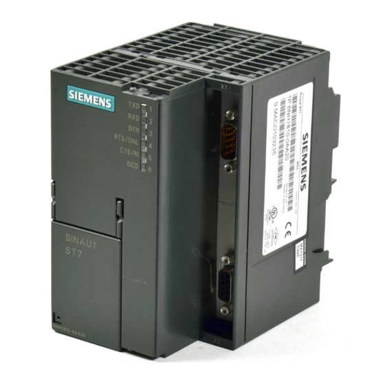
S I N A U T S T 7 Information about the current hardware version 6NH7810-0AA20 Order number of the modem Fig. 2-1 Front view of the MD2 modem with closed front doors 6NH7811-0AA22 © Siemens AG 2002 All Rights Reserved MD2 Modem (07/2002) -
Page 22: Led Display Of The Md2
It goes out when this received level is no longer detected. The inscriptions ONL and RI are not relevant for the MD2. © Siemens AG 2002 All Rights Reserved 6NH7811-0AA22 MD2 Modem (07/2002) -
Page 23: Front View Of An Md2 With Removed Front Doors
Access (from below) to the X3 WAN connection socket of the modem (6-pin RJ12 Western socket) Connection for DC 24 V power supply Fig. 2-2 Front view of the MD2 modem with removed front doors 6NH7811-0AA22 © Siemens AG 2002 All Rights Reserved MD2 Modem (07/2002) -
Page 24: Pin Assignments For The Rs232 And Rs485 Ports
*) It is recommended to activate the terminating resistor for the RS485 bus in the plug and not in the modem itself. The recommended RS485 setting in the modem is shown in Fig. 2-6. © Siemens AG 2002 All Rights Reserved 6NH7811-0AA22... -
Page 25: Standard Cables For The Rs232 And Rs485 Ports
(DTE) with an identically configured 25-pin RS232 interface (socket) and screw lock. Cable length 1.0 m TIM011B The following tables show you how the cables mentioned above are configured. 6NH7811-0AA22 © Siemens AG 2002 All Rights Reserved MD2 Modem (07/2002) - Page 26 9-pin Table 2-7 Configuration of standard cable 6NH7701-1CB Modem MD2 Pin no. Connection Pin no. Modem MD2 (RS232) (RS232) Housing Housing shell shell Sub-D socket Sub-D socket 9-pin 9-pin © Siemens AG 2002 All Rights Reserved 6NH7811-0AA22 MD2 Modem (07/2002)
- Page 27 Sub-D Plug 25-pin Table 2-9 Configuration of Standard Cable 6NH1701-7BK DTE/TIM011B Pin no. Connection Pin no. MD3 Modem (RS232) (RS232) Sub-D socket RI / T 9-pin Sub-D Plug 25-pin 6NH7811-0AA22 © Siemens AG 2002 All Rights Reserved MD2 Modem (07/2002)
-
Page 28: View Of The Md2 Modem From Above
· 5-pin DIL switch Send level –6 dB or 0 dB 2-wire or 4-wire mode One channel or two channel for 2-wire mode Baud rate 1200, 2400, 9600 or 19200 © Siemens AG 2002 All Rights Reserved 6NH7811-0AA22 MD2 Modem (07/2002) - Page 29 M I D: Message interval detection Fig. 2-4 Various settings for the DIL switches accessible from above The following sections provide more information for individually configuring these default settings. 6NH7811-0AA22 © Siemens AG 2002 All Rights Reserved 2-10 MD2 Modem (07/2002)
- Page 30 10pin DIL switch (see page 2-15) a reduced level of –9 dB (standard for leased lines) can be set instead of 0 dB or instead of –6 dB the level can be reduced to –15 dB. © Siemens AG 2002 All Rights Reserved 6NH7811-0AA22...
- Page 31 Test mode: Test f H constant In this test mode the upper keying frequency is continuously present 1 2 3 4 5 6 7 8 9 10 at the modem transmitter output. 6NH7811-0AA22 © Siemens AG 2002 All Rights Reserved 2-12 MD2 Modem (07/2002)
- Page 32 Switch off the power supply of the modem and make the desired settings using the DIL switch. When the power is switched on the selected settings for the character recognition become active. © Siemens AG 2002 All Rights Reserved 6NH7811-0AA22 2-13...
- Page 33 1 2 3 4 5 6 7 8 9 10 This is the standard setting for sending SINAUT ST1 or SINAUT ST7 messages. In this case message format FT 1.2, based on 11-bit asynchronous characters, is normally used for transmitting over dedicated lines.
-
Page 34: Other Settings
–15dB depending on the setting of switch S1 (5-pin DIL switch). Note Details about the control output, squelch function and resetting 'Test receive' are available in Chapter 4 Operating Modes and Character Recognition. © Siemens AG 2002 All Rights Reserved 6NH7811-0AA22 2-15 MD2 Modem (07/2002) - Page 35 With the factory default settings the switches appear as shown in the following illustration. 1 2 3 4 5 1 2 3 4 5 6 7 8 9 10 Fig. 2-5 Factory default settings for DIL switches 6NH7811-0AA22 © Siemens AG 2002 All Rights Reserved 2-16 MD2 Modem (07/2002)
-
Page 36: View Of The Md2 Modem From Below
RS485 port active, terminating resistor not 1 2 3 4 active. Needs to be set on last plug! See Fig. 2-13 Fig. 2-6 View of the MD2 modem from below © Siemens AG 2002 All Rights Reserved 6NH7811-0AA22 2-17 MD2 Modem (07/2002) -
Page 37: Dil Switch For Activating The Rs232 Or Rs485 Port
1 2 3 4 600 Ohm, Channel 2 150 Ohm, Channel 1 150 Ohm, Channel 2 600 Ohm, Channel 1 Fig. 2-8 Various settings for terminating resistors at the WAN end 6NH7811-0AA22 © Siemens AG 2002 All Rights Reserved 2-18 MD2 Modem (07/2002) -
Page 38: Pin Assignments On The Rj12 Western Socket
The following is the technical data for this output: · max. connection voltage = 60V AC/DC · max = 3 Ohm · I max = 400 mA A suppression circuit is not provided for the output. © Siemens AG 2002 All Rights Reserved 6NH7811-0AA22 2-19 MD2 Modem (07/2002) -
Page 39: Standard Cable For The Rj12 Port
When inserting the cable it is best to hold it directly below the RJ12 plug. The insertion is then considerably easier than when holding the cable by the RJ12 plug. Make sure that the RJ12 plug clearly clicks when it is inserted! 6NH7811-0AA22 © Siemens AG 2002 All Rights Reserved 2-20 MD2 Modem (07/2002) -
Page 40: Connecting An Md2 To Dte, Ltop And Dedicated Line
6NH9821-0BC11 6NH9821-0BC12 2-wire 4-wire dedicated line dedicated line Fig. 2-10 Connection of an MD2 with a DTE via RS232, configuration as 2-wire and 4-wire terminal points © Siemens AG 2002 All Rights Reserved 6NH7811-0AA22 2-21 MD2 Modem (07/2002) - Page 41 2-wire tapping point Fig. 2-11 Connection of an MD2 with a DTE (e.g. TIM) via RS232, configuration as 2 x 2-wire terminal point and 2-wire tapping point 6NH7811-0AA22 © Siemens AG 2002 All Rights Reserved 2-22 MD2 Modem (07/2002)
- Page 42 6NH7700-2AR60 LTOP2 LTOP2 LTOP2 overvoltage protection 6NH9821-0BC12 4-wire tapping point Fig. 2-12 Connection of an MD2 with a DTE (e.g. TIM) via RS232, configuration as 4-wire tapping point © Siemens AG 2002 All Rights Reserved 6NH7811-0AA22 2-23 MD2 Modem (07/2002)
-
Page 43: Connecting Several Md2S With A Dte Via The Rs485 Port
4-wire 2-wire dedicated line dedicated line dedicated line dedicated line Fig. 2-13 Connecting several MD2s with a DTE (e.g. TIM) via RS485, star-shaped junction of several dedicated lines 6NH7811-0AA22 © Siemens AG 2002 All Rights Reserved 2-24 MD2 Modem (07/2002) - Page 44 2) The RS485 interface must also be activated with the 4-pin DIL switch accessible from below (see Fig. 2-6). 3) If the DTE connected to the MD2 modem is a SINAUT ST7 TIM, follow the instructions in the SINAUT ST7 Manual, Chapter 5.1.4.
- Page 45 9-pin Table 2-19 Connection to the third MD2 modem etc. Connection Pin no. Modem MD2 (RS485) Shielding Data A A1 (8) Data B B1 (3) Sub-D plug 9-pin 6NH7811-0AA22 © Siemens AG 2002 All Rights Reserved 2-26 MD2 Modem (07/2002)
-
Page 46: Connecting Two Md2S To Function As A Repeater
2-wire 2-wire tapping point terminal point terminal point Fig. 2-14 Two MD2s as a 2-wire repeater combined with a 2-wire tapping of a DTE (e.g. TIM32 or TIM42) © Siemens AG 2002 All Rights Reserved 6NH7811-0AA22 2-27 MD2 Modem (07/2002) -
Page 47: Transmission Speeds And Frequencies Of The Md2 Modem
(Hz) (Hz) (Hz) (Hz) 1200 1 700 1 300 2 100 2400 2 850 2400 3 300 9600 / 19200 27 200 6 400 20 800 33 600 6NH7811-0AA22 © Siemens AG 2002 All Rights Reserved 2-28 MD2 Modem (07/2002) -
Page 48: Signal Loss Values
23.3 – NTP x 2.9 26 – NTP x 0.2 NTP = number of tapping points *) not permitted on telecom leased lines. Set send level to –9 dB. © Siemens AG 2002 All Rights Reserved 6NH7811-0AA22 2-29 MD2 Modem (07/2002) - Page 49 There is no need to calculate the maximum range for telecom leased lines. The telecom is responsible for providing a sufficient signal level. Recommended cable quality for telecom leased lines: Analog fixed line connections, type M.1020 or M.1025. 6NH7811-0AA22 © Siemens AG 2002 All Rights Reserved 2-30 MD2 Modem (07/2002)
-
Page 50: Determination Of The Receive Level
-35 dB 13,7 mV -6 dB 389 mV -18 dB 97,8 mV -40 dB 7,8 mV -9 dB 274 mV -20 dB 77,7 mV -43 dB 5,5 mV © Siemens AG 2002 All Rights Reserved 6NH7811-0AA22 2-31 MD2 Modem (07/2002) -
Page 51: Ltop Line Transformer With Overvoltage Protection
Suppressor diode to limit the secondary voltage of the transformer (V1) Dedicated line Modem Fig. 2-16 Circuit diagram of an LTOP unit Fig. 2-17 Location of circuit elements in an LTOP2 (viewed from above) 6NH7811-0AA22 © Siemens AG 2002 All Rights Reserved 2-32 MD2 Modem (07/2002) - Page 52 X2 + X3 Modem connection 4-wire through screw terminal 2-Wire/4-wire modem connection via RJ12 Western connector; for direct connection of the SINAUT ST7 MD2 modem via the standard interconnecting cable (RJ12 – RJ12) which is supplied with this modem. S1 + S2 Adjustment switches ©...
-
Page 53: Connecting The Md2 Modem
For more detailed information refer to section 2.1.10 DIL Switch for Activating Terminating Resistors. Important Please take care that the switches S1 and S2 are in the correct position 1 or 2 as shown in the following figures! 6NH7811-0AA22 © Siemens AG 2002 All Rights Reserved 2-34 MD2 Modem (07/2002) - Page 54 4-wire dedicated line 1 dedicated 2-wire line dedicated line 2 Fig. 2-21 Connection of the MD2 to an LTOP2 at a 4-wire or 2 x 2-wire terminal point © Siemens AG 2002 All Rights Reserved 6NH7811-0AA22 2-35 MD2 Modem (07/2002)
- Page 55 2 5 3 4 LTOP2 LTOP2 4-wire 4-wire dedicated dedicated line #1 line #2 Fig. 2-23 Connection of the MD2 to two LTOP2s at a 4-wire tapping point 6NH7811-0AA22 © Siemens AG 2002 All Rights Reserved 2-36 MD2 Modem (07/2002)
-
Page 56: Mounting
When inserting the cable it is best to hold it directly below the RJ12 plug. The insertion is then considerably easier than when holding the cable by the RJ12 plug. Make sure that the RJ12 plug clearly clicks when it is inserted! © Siemens AG 2002 All Rights Reserved 6NH7811-0AA22 2-37... -
Page 57: Mounting On A Standard 35Mm Mounting Rail
Screw the modem tight on the adapter. Now the modem is ready for mounting on the standard rail and can clipped into place. The remaining steps for mounting are similar to those described in section 2.4.1 Mounting on an S7-300 Mounting Rail. 6NH7811-0AA22 © Siemens AG 2002 All Rights Reserved 2-38 MD2 Modem (07/2002) -
Page 58: Horizontal And Vertical Mounting
Assembly dimensions of the MD2 modem Module Module Module Max. width height depth req. MD2 modem module 80 mm 125 mm 120 mm or 180 mm with open front plate © Siemens AG 2002 All Rights Reserved 6NH7811-0AA22 2-39 MD2 Modem (07/2002) -
Page 59: Connecting To The Power Supply
2. Connect the power supply cables to the modem: M and L+ 3. Close the front doors. Important To avoid ground loops you should not connect the shielding of the modem. 6NH7811-0AA22 © Siemens AG 2002 All Rights Reserved 2-40 MD2 Modem (07/2002) -
Page 60: Connection Diagram
TIM4. The same connection scheme applies for all of these modules. ··· Power Supply TIM3/TIM4 Modem #1 Last Modem DC 24 V Fig. 2-25 Connecting to the power supply © Siemens AG 2002 All Rights Reserved 6NH7811-0AA22 2-41 MD2 Modem (07/2002) -
Page 61: Mounting And
Mounting and Installation 6NH7811-0AA22 © Siemens AG 2002 All Rights Reserved 2-42 MD2 Modem (07/2002) -
Page 62: Instructions For
Connecting the MD2 to a TIM11 and TIM011B........3-3 3.2.1 Modem Settings ..................... 3-4 3.2.2 Configuration Required for TIM11 and TIM011B ........3-6 3.2.3 Avoiding Problems When Exchanging Modems ........3-6 © Siemens AG 2002 All Rights Reserved 6NH7811-0AA22 MD2 Modem (07/2002) -
Page 63: Operating Modes And
2. You can use the MD2 modem as a replacement for a defective ST1 dedicated line modem. Note A new SINAUT ST1 station might also be a SINAUT ST7 device with an MD2 operating as an ST1 station. For most applications it is possible to connect the MD2 modem to a SINAUT ST1 device without any special considerations having to be made. -
Page 64: Connecting The Md2 To A Tim11 And Tim011B
RS232 interface (socket) and screw lock. Cable length 1.0 m TIM011B The section 'Standard Cables for the RS232 Port' in Chapter 2 provides a description of this cable's configuration. © Siemens AG 2002 All Rights Reserved 6NH7811-0AA22 MD2 Modem (07/2002) -
Page 65: Modem Settings
1 2 3 MD124 and LGM 1200H1. Baud rate 2400 bps (see also Note) At this speed the modem is compatible to SINAUT ST1 modem MD124. 1 2 3 6NH7811-0AA22 © Siemens AG 2002 All Rights Reserved MD2 Modem (07/2002) - Page 66 In this mode a message consists of a series of asynchronous characters, 11-bit each (1 start bit, 8 data bits, 1 parity bit, 1 stop bit). This is the standard setting for sending SINAUT ST1 or SINAUT ST7 1 2 3 4...
-
Page 67: Configuration Required For Tim11 And Tim011B
If the MD2 is used in a network together with an MD124 at baud rate 2400 bps and the MD124 is hardware version ≤ 3, the MD124 has to be set to baud rate 2400VF. 6NH7811-0AA22 © Siemens AG 2002 All Rights Reserved MD2 Modem (07/2002) -
Page 68: Operating Modes And Character Recognition
Character Recognition of the MD2 ............4-23 4.2.1 Character Recognition "Asynchronous 11 Bit" ........4-24 4.2.2 Character Recognition "Asynchronous 10 Bit" ........4-24 4.2.3 "MID on" Character Recognition ............4-25 4.2.4 "MID off" Character Recognition ............4-26 © Siemens AG 2002 All Rights Reserved 6NH7811-0AA22 MD2 Modem (07/2002) - Page 69 300 and 600 bps. A detailed description of the character recognition and its properties is available in section 4.2 Character Recognition of the MD2. 6NH7811-0AA22 © Siemens AG 2002 All Rights Reserved MD2 Modem (07/2002)
-
Page 70: Md2 Operating Modes
· Test operating mode Test receive The setting for the operating mode is made on switches 1 to 4 of the 10-pin DIL switch which can be accessed from above through the housing grid. © Siemens AG 2002 All Rights Reserved 6NH7811-0AA22 MD2 Modem (07/2002) - Page 71 MD2 operating modes. A few examples of the various network configurations and the corresponding settings on the MD2 modem are available in Chapter 5 Network Configurations. 6NH7811-0AA22 © Siemens AG 2002 All Rights Reserved MD2 Modem (07/2002)
-
Page 72: Normal" Operating Mode
"Normal with DTR/RTS on" operating mode. 1 2 3 4 5 6 7 8 9 10 Fig. 4-2 DIL switch setting for the "Normal with DTR/RTS on" operating mode © Siemens AG 2002 All Rights Reserved 6NH7811-0AA22 MD2 Modem (07/2002) -
Page 73: Repeater" Operating Mode
The following illustration shows the setting on the 10-pin DIL switch of the MD2 for the "Repeater" operating mode. 1 2 3 4 5 6 7 8 9 10 Fig. 4-3 DIL switch setting for the "Repeater" operating mode 6NH7811-0AA22 © Siemens AG 2002 All Rights Reserved MD2 Modem (07/2002) -
Page 74: With Rs485 Interface" Operating Mode
The following illustration shows the setting on the 10-pin DIL switch of the MD2 for the "With RS485 interface" operating mode. 1 2 3 4 5 6 7 8 9 10 Fig. 4-4 DIL switch setting for the "With RS485 interface" operating mode © Siemens AG 2002 All Rights Reserved 6NH7811-0AA22 MD2 Modem (07/2002) -
Page 75: Signal Refresh Off" Operating Mode
The following illustration shows the setting on the 10-pin DIL switch of the MD2 for the "Signal refresh off" operating mode. 1 2 3 4 5 6 7 8 9 10 Fig. 4-5 DIL switch setting for the "Signal refresh off" operating mode 6NH7811-0AA22 © Siemens AG 2002 All Rights Reserved MD2 Modem (07/2002) -
Page 76: Test Operating Modes
Some notes to this can be found below under Possible Error Causes. All options for the dedicated line properties can be selected but the character recognition method must be set to either "Asynchronous 10" or "Asynchronous 11". © Siemens AG 2002 All Rights Reserved 6NH7811-0AA22 MD2 Modem (07/2002) - Page 77 · Cable damage: Cable isolation defective, earth fault, water penetration, etc. · Crosstalk in the cable. · etc. 6NH7811-0AA22 © Siemens AG 2002 All Rights Reserved 4-10 MD2 Modem (07/2002)
- Page 78 MD2 will signalize this by its "DCD" LED that is constantly on. If the "DCD" LED stays off or flashes irregularly; then this indicates an incorrect data reception. For possible causes: see section Possible Error Causes. © Siemens AG 2002 All Rights Reserved 6NH7811-0AA22 4-11...
- Page 79 Test operating mode "Test f " is not suitable for measuring the level over the dedicated line. Use operating mode "Test f " for making exact H constant measurements of the level. 6NH7811-0AA22 © Siemens AG 2002 All Rights Reserved 4-12 MD2 Modem (07/2002)
- Page 80 MD2 will signalize this by its "RXD" and "DCD" LEDs that both are constantly on. If the "RXD" and "DCD" LEDs stay off or flash irregularly; then this indicates an incorrect data reception. For possible causes: see section Possible Error Causes. © Siemens AG 2002 All Rights Reserved 6NH7811-0AA22 4-13...
- Page 81 Test operating mode "Test f " is not suitable for measuring the level over the dedicated line. Use operating mode "Test f " for making exact H constant measurements of the level. 6NH7811-0AA22 © Siemens AG 2002 All Rights Reserved 4-14 MD2 Modem (07/2002)
- Page 82 MD2 will signalize this by its "RXD" and "DCD" LEDs that both are constantly on. If the "RXD" and "DCD" LEDs stay off or flash irregularly; then this indicates an incorrect data reception. For possible causes: see section Possible Error Causes. © Siemens AG 2002 All Rights Reserved 6NH7811-0AA22 4-15...
- Page 83 " is not suitable for measuring the level over the baud dedicated line. Use operating mode "Test f " for making exact H constant measurements of the level. 6NH7811-0AA22 © Siemens AG 2002 All Rights Reserved 4-16 MD2 Modem (07/2002)
- Page 84 -35 dB 13,7 mV -6 dB 389 mV -18 dB 97,8 mV -40 dB 7,8 mV -9 dB 274 mV -20 dB 77,7 mV -43 dB 5,5 mV © Siemens AG 2002 All Rights Reserved 6NH7811-0AA22 4-17 MD2 Modem (07/2002)
- Page 85 "Test receive" Cable Cable 6NH7700-2AR60 6NH7700-2AR60 LTOP1 LTOP1 overvoltage overvoltage LTOP1 LTOP1 protection protection 6NH9821-0BC11 6NH9821-0BC11 2-wire dedicated line Fig. 4-13 Test configuration for operating mode "Test send" 6NH7811-0AA22 © Siemens AG 2002 All Rights Reserved 4-18 MD2 Modem (07/2002)
- Page 86 The following illustration shows the setting on the 10-pin DIL switch of the MD2 for the "Test send" operating mode. 1 2 3 4 5 6 7 8 9 10 Fig. 4-14 DIL switch setting for the "Test send" operating mode © Siemens AG 2002 All Rights Reserved 6NH7811-0AA22 4-19 MD2 Modem (07/2002)
- Page 87 6NH7700-2AR60 switch (accessable from below) LTOP1 LTOP1 overvoltage overvoltage LTOP1 LTOP1 protection protection 6NH9821-0BC11 6NH9821-0BC11 2-wire dedicated line Fig. 4-15 Test configuration for operating mode "Test send RS485" 6NH7811-0AA22 © Siemens AG 2002 All Rights Reserved 4-20 MD2 Modem (07/2002)
- Page 88 "Test send RS485" operating mode. 1 2 3 4 5 6 7 8 9 10 Fig. 4-16 DIL switch setting for the "Test send RS485" operating mode © Siemens AG 2002 All Rights Reserved 6NH7811-0AA22 4-21 MD2 Modem (07/2002)
- Page 89 The "DTR" and "CTS" LEDs will go off, "Test receive" is restarted. If these LEDs go on again, a new error has been detected in the received character string and is stored. Fig. 4-18 Reset "Test receive" 6NH7811-0AA22 © Siemens AG 2002 All Rights Reserved 4-22 MD2 Modem (07/2002)
-
Page 90: Character Recognition Of The Md2
The synchronization of the signal refresh logic therefore only occurs once for every message or data block. The "MID on" character recognition methods available on the MD2 operate according to message interval detection. © Siemens AG 2002 All Rights Reserved 6NH7811-0AA22 4-23 MD2 Modem (07/2002) -
Page 91: Character Recognition "Asynchronous 11 Bit
The following illustration shows the setting on the 10-pin DIL switch of the MD2 for "Asynchronous 10 bit" character recognition. 1 2 3 4 5 6 7 8 9 10 Fig. 4-22 DIL switch setting for the "Asynchronous 10 bit" character recognition 6NH7811-0AA22 © Siemens AG 2002 All Rights Reserved 4-24 MD2 Modem (07/2002) -
Page 92: Mid On" Character Recognition
8 9 10 ³ 24 1200, 2400, 4800, 9600, bits long 19200 MID on (interval ³ 24) idle state 1 1 2 3 4 5 6 7 8 9 10 © Siemens AG 2002 All Rights Reserved 6NH7811-0AA22 4-25 MD2 Modem (07/2002) -
Page 93: Mid Off" Character Recognition
5 6 7 8 9 10 300, 600, unlimited 1200, 2400, 4800, 9600, MID off 19200 idle state 1 1 2 3 4 5 6 7 8 9 10 6NH7811-0AA22 © Siemens AG 2002 All Rights Reserved 4-26 MD2 Modem (07/2002) -
Page 94: Network Configurations
5.2.5 Star Network, 2-Wire Half-duplex (RS485 Interface)..........5-42 5.2.6 Repeater, 2-Wire Half-duplex (RS485 Interface) .............5-46 Network Configurations for DTE without RTS/CTS ..........5-50 5.3.1 Point-to-Point, 4-wire Full-duplex................5-51 5.3.2 Point-to-Point with Repeater, 4-wire Full-duplex............5-53 © Siemens AG 2002 All Rights Reserved 6NH7811-0AA22 MD2 Modem (07/2002) -
Page 95: Network Configurations With Rs232
Star network via Normal 2-wire half-duplex 5.1.6 external multiple transformer Star network via external multiple Normal 4-wire full-duplex 5.1.7 transformer Repeater Repeater 4-wire full-duplex 5.1.8 Repeater Repeater 2-wire half-duplex 5.1.9 6NH7811-0AA22 © Siemens AG 2002 All Rights Reserved MD2 Modem (07/2002) -
Page 96: Point-To-Point, 4-Wire Full-Duplex
Cable Cable 6NH7700-2AR60 6NH7700-2AR60 Terminal point Terminal point LTOP2 LTOP2 overvoltage overvoltage LTOP2 LTOP2 protection protection 6NH9821-0BC12 6NH9821-0BC12 4-wire dedicated line Fig. 5-1 Network configuration: point-to-point, 4-wire full-duplex network © Siemens AG 2002 All Rights Reserved 6NH7811-0AA22 MD2 Modem (07/2002) - Page 97 Settings on the LTOP2 switches Switch Switch Note position Receive channel (pins 2 and 5) activated Switch S1 (see Fig. 2-18) Send channel (pins 3 and 4) activated Switch S2 (see Fig. 2-18) 6NH7811-0AA22 © Siemens AG 2002 All Rights Reserved MD2 Modem (07/2002)
-
Page 98: Point-To-Point, 2-Wire Half-Duplex
RS232 Cable Cable 6NH7700-2AR60 6NH7700-2AR60 Terminal point Terminal point LTOP1 LTOP1 overvoltage overvoltage LTOP1 LTOP1 protection protection 6NH9821-0BC11 6NH9821-0BC11 2-wire dedicated line Fig. 5-2 Network configuration: point-to-point, 2-wire half-duplex © Siemens AG 2002 All Rights Reserved 6NH7811-0AA22 MD2 Modem (07/2002) - Page 99 RS232 interface (see Fig. 2-6) 1 2 3 4 Settings on the LTOP1 switch Switch Switch Note position 2-wire channel (pins 2 and 5) activated Switch S1 (see Fig. 2-18) 6NH7811-0AA22 © Siemens AG 2002 All Rights Reserved MD2 Modem (07/2002)
-
Page 100: Multidrop Line, 4-Wire Full-Duplex
Network configuration: multidrop line, 4-wire full-duplex Fig. 5-3 illustrates only one tapping point. Each additional tapping point is identical to this and the settings on the MD2 and both LTOPs are the same. © Siemens AG 2002 All Rights Reserved 6NH7811-0AA22 MD2 Modem (07/2002) - Page 101 Settings on the LTOP2 switches Switch Switch Note position Receive channel (pins 2 and 5) activated Switch S1 (see Fig. 2-18) Send channel (pins 3 and 4) activated Switch S2 (see Fig. 2-18) 6NH7811-0AA22 © Siemens AG 2002 All Rights Reserved MD2 Modem (07/2002)
- Page 102 Settings on the switches of both LTOP2s Switch Switch Note position Receive channel (pins 2 and 5) activated Switch S1 (see Fig. 2-18) Send channel (pins 3 and 4) activated Switch S2 (see Fig. 2-18) © Siemens AG 2002 All Rights Reserved 6NH7811-0AA22 MD2 Modem (07/2002)
-
Page 103: Multidrop Line, 2-Wire Half-Duplex
Network configuration: multidrop line, 2-wire half-duplex Fig. 5-4 illustrates only one tapping point. Each additional tapping point is identical to this and the settings on the MD2 and both LTOPs are the same. 6NH7811-0AA22 © Siemens AG 2002 All Rights Reserved 5-10 MD2 Modem (07/2002) - Page 104 (see Fig. 2-6) 1 2 3 4 Settings on the LTOP1 switch Switch Switch Note position 2-wire channel (pins 2 and 5) activated Switch S1 (see Fig. 2-18) © Siemens AG 2002 All Rights Reserved 6NH7811-0AA22 5-11 MD2 Modem (07/2002)
- Page 105 Switch Switch Note position 2-wire channel (pins 2 and 5) activated Switch S1 (see Fig. 2-18) 2-wire channel (pins 2 and 5) activated Switch S2 (see Fig. 2-18) 6NH7811-0AA22 © Siemens AG 2002 All Rights Reserved 5-12 MD2 Modem (07/2002)
-
Page 106: Star Network Via The Md2-Internal Two-Way Transformer, 2-Wire Half-Duplex
6NH9821-0BC12 2 x 2-wire- 1. 2. dedicated line To more 2-wire stations dedicated line Fig. 5-5 Network configuration: star network via the MD2-internal two-way transformer, 2-wire half- duplex © Siemens AG 2002 All Rights Reserved 6NH7811-0AA22 5-13 MD2 Modem (07/2002) - Page 107 Note position First 2-wire channel (pins 2 and 5) activated Switch S1 (see Fig. 2-18) Second 2-wire channel (pins 3 and 4) activated Switch S2 (see Fig. 2-18) 6NH7811-0AA22 © Siemens AG 2002 All Rights Reserved 5-14 MD2 Modem (07/2002)
- Page 108 (see Fig. 2-6) 1 2 3 4 Settings on the LTOP1 switch Switch Switch Note position 2-wire channel (pins 2 and 5) activated Switch S1 (see Fig. 2-18) © Siemens AG 2002 All Rights Reserved 6NH7811-0AA22 5-15 MD2 Modem (07/2002)
- Page 109 Switch Switch Note position 2-wire channel (pins 2 and 5) activated Switch S1 (see Fig. 2-18) 2-wire channel (pins 2 and 5) activated Switch S2 (see Fig. 2-18) 6NH7811-0AA22 © Siemens AG 2002 All Rights Reserved 5-16 MD2 Modem (07/2002)
-
Page 110: Star Network Via An External Multiple Transformer, 2-Wire Half-Duplex
LTOP2 LTOP2 6NH9821-0BC12 4 x 2-wire- 1. 2. 3. 4. 2-wire dedicated line dedicated line Fig. 5-6 Network configuration: star network via an external multiple transformer, 2-wire half-duplex © Siemens AG 2002 All Rights Reserved 6NH7811-0AA22 5-17 MD2 Modem (07/2002) - Page 111 (see Fig. 2-18) Settings on the LTOP1 Switch (LTOP1 at modem in the middle) Switch Switch Note position 2-wire channel (pins 2 and 5) activated Switch S1 (see Fig. 2-18) 6NH7811-0AA22 © Siemens AG 2002 All Rights Reserved 5-18 MD2 Modem (07/2002)
- Page 112 Switch Switch Note position 2-wire channel (pins 2 and 5) activated Switch S1 (see Fig. 2-18) 2-wire channel (pins 2 and 5) activated Switch S2 (see Fig. 2-18) © Siemens AG 2002 All Rights Reserved 6NH7811-0AA22 5-19 MD2 Modem (07/2002)
- Page 113 1) Two 4-way transformers can be connected to the MD2, this means that a total of eight 2-wire dedicated lines can be connected. The MD2 then has to be configured as a 2 x 2-wire terminal point. 6NH7811-0AA22 © Siemens AG 2002 All Rights Reserved 5-20 MD2 Modem (07/2002)
-
Page 114: Star Network Via An External Multiple Transformer, 4-Wire Full-Duplex
1200 or 2400 bps LTOP2 overvoltage LTOP2 LTOP2 LTOP2 LTOP2 protection 6NH9821-0BC12 4 x 4-wire- dedicated line Fig. 5-7 Network configuration: star network via an external multiple transformer, 4-wire full-duplex © Siemens AG 2002 All Rights Reserved 6NH7811-0AA22 5-21 MD2 Modem (07/2002) - Page 115 Switch Switch Note position Receive channel (pins 2 and 5) activated Switch S1 (see Fig. 2-18) Send channel (pins 3 and 4) activated Switch S2 (see Fig. 2-18) 6NH7811-0AA22 © Siemens AG 2002 All Rights Reserved 5-22 MD2 Modem (07/2002)
- Page 116 Name Direction 1 2 3 4 5 6 Connection of the multiple transformer for the Input receiving direction Connection of the multiple transformer for the Output sending direction © Siemens AG 2002 All Rights Reserved 6NH7811-0AA22 5-23 MD2 Modem (07/2002)
-
Page 117: Repeater, 4-Wire Full-Duplex
Repeater Repeater LTOP2 LTOP2 overvoltage overvoltage LTOP2 LTOP2 LTOP2 LTOP2 LTOP2 protection protection 6NH9821-0BC12 6NH9821-0BC12 4-wire 4-wire dedicated line dedicated line Fig. 5-8 Network configuration: repeater, 4-wire full-duplex 6NH7811-0AA22 © Siemens AG 2002 All Rights Reserved 5-24 MD2 Modem (07/2002) - Page 118 Switch Switch Note position Receive channel (pins 2 and 5) activated Switch S1 (see Fig. 2-18) Send channel (pins 3 and 4) activated Switch S2 (see Fig. 2-18) © Siemens AG 2002 All Rights Reserved 6NH7811-0AA22 5-25 MD2 Modem (07/2002)
- Page 119 Switch Switch Note position Receive channel (pins 2 and 5) activated Switch S1 (see Fig. 2-18) Send channel (pins 3 and 4) activated Switch S2 (see Fig. 2-18) 6NH7811-0AA22 © Siemens AG 2002 All Rights Reserved 5-26 MD2 Modem (07/2002)
- Page 120 Switch Switch Note position Receive channel (pins 2 and 5) activated Switch S1 (see Fig. 2-18) Send channel (pins 3 and 4) activated Switch S2 (see Fig. 2-18) © Siemens AG 2002 All Rights Reserved 6NH7811-0AA22 5-27 MD2 Modem (07/2002)
-
Page 121: Repeater, 2-Wire Half-Duplex
Repeater Tapping point LTOP1 LTOP2 overvoltage overvoltage LTOP1 LTOP1 LTOP1 LTOP2 protection protection 6NH9821-0BC11 6NH9821-0BC12 2-wire 2-wire dedicated line dedicated line Fig. 5-9 Network configuration: repeater, 2-wire half-duplex 6NH7811-0AA22 © Siemens AG 2002 All Rights Reserved 5-28 MD2 Modem (07/2002) - Page 122 (see Fig. 2-6) 1 2 3 4 Settings on the LTOP1 switch Switch Switch Note position 2-wire channel (pins 2 and 5) activated Switch S1 (see Fig. 2-18) © Siemens AG 2002 All Rights Reserved 6NH7811-0AA22 5-29 MD2 Modem (07/2002)
- Page 123 Switch Switch Note position 2-wire channel (pins 2 and 5) activated Switch S1 (see Fig. 2-18) 2-wire channel (pins 2 and 5) activated Switch S2 (see Fig. 2-18) 6NH7811-0AA22 © Siemens AG 2002 All Rights Reserved 5-30 MD2 Modem (07/2002)
- Page 124 (see Fig. 2-6) 1 2 3 4 Settings on the LTOP1 switch Switch Switch Note position 2-wire channel (pins 2 and 5) activated Switch S1 (see Fig. 2-18) © Siemens AG 2002 All Rights Reserved 6NH7811-0AA22 5-31 MD2 Modem (07/2002)
-
Page 125: Network Configurations With Rs485
Multidrop line with with RS485 2-wire half-duplex 5.2.4 fiber optic section interface with RS485 Star network 2-wire half-duplex 5.2.5 interface with RS485 Repeater 2-wire half-duplex 5.2.6 interface 6NH7811-0AA22 © Siemens AG 2002 All Rights Reserved 5-32 MD2 Modem (07/2002) -
Page 126: Point-To-Point, 2-Wire Half-Duplex (Rs485 Interface)
6NH7700-2AR60 6NH7700-2AR60 Terminal point Terminal point LTOP1 LTOP1 overvoltage overvoltage LTOP1 LTOP1 protection protection 6NH9821-0BC11 6NH9821-0BC11 2-wire dedicated line Fig. 5-10 Network configuration: Point-to-point, 2-wire half-duplex (RS485 interface) © Siemens AG 2002 All Rights Reserved 6NH7811-0AA22 5-33 MD2 Modem (07/2002) - Page 127 (see Fig. 2-6) 1 2 3 4 Settings on the LTOP1 switch Switch Switch Note position 2-wire channel (pins 2 and 5) activated Switch S1 (see Fig. 2-18) 6NH7811-0AA22 © Siemens AG 2002 All Rights Reserved 5-34 MD2 Modem (07/2002)
-
Page 128: Point-To-Point With Fiber Optic Section, 2-Wire Half-Duplex (Rs485 Interface)
LTOP1 LTOP1 protection protection 6NH9821-0BC11 6NH9821-0BC11 FOm: fiber 2-wire optic module dedicated line Fig. 5-11 Network configuration: Point-to-point with fiber optic section, 2-wire half-duplex (RS485 interface) © Siemens AG 2002 All Rights Reserved 6NH7811-0AA22 5-35 MD2 Modem (07/2002) - Page 129 (see Fig. 2-6) 1 2 3 4 Settings on the LTOP1 switch Switch Switch Note position 2-wire channel (pins 2 and 5) activated Switch S1 (see Fig. 2-18) 6NH7811-0AA22 © Siemens AG 2002 All Rights Reserved 5-36 MD2 Modem (07/2002)
-
Page 130: Multidrop Line, 2-Wire Half-Duplex (Rs485 Interface)
LTOP1 LTOP1 LTOP2 protection protection protection 6NH9821-0BC11 6NH9821-0BC12 6NH9821-0BC11 2-wire 2-wire dedicated line dedicated line Fig. 5-12 Network configuration: Multidrop line, 2-wire half-duplex (RS485 interface) © Siemens AG 2002 All Rights Reserved 6NH7811-0AA22 5-37 MD2 Modem (07/2002) - Page 131 (see Fig. 2-6) 1 2 3 4 Settings on the LTOP1 switch Switch Switch Note position 2-wire channel (pins 2 and 5) activated Switch S1 (see Fig. 2-18) 6NH7811-0AA22 © Siemens AG 2002 All Rights Reserved 5-38 MD2 Modem (07/2002)
- Page 132 Switch Switch Note position 2-wire channel (pins 2 and 5) activated Switch S1 (see Fig. 2-18) 2-wire channel (pins 2 and 5) activated Switch S2 (see Fig. 2-18) © Siemens AG 2002 All Rights Reserved 6NH7811-0AA22 5-39 MD2 Modem (07/2002)
-
Page 133: Multidrop Line With Fiber Optic Section, 2-Wire Half-Duplex (Rs485 Interface)
LTOP1 LTOP1 RS485 RS485 LTOP1 6NH9821 0BC11 FOm: fiber 2-wire optic module dedicated line Fig. 5-13 Network configuration: Multidrop line with fiber optic section, 2-wire half-duplex (RS485 interface) 6NH7811-0AA22 © Siemens AG 2002 All Rights Reserved 5-40 MD2 Modem (07/2002) - Page 134 (see Fig. 2-6) 1 2 3 4 Settings on the LTOP1 switch Switch Switch Note position 2-wire channel (pins 2 and 5) activated Switch S1 (see Fig. 2-18) © Siemens AG 2002 All Rights Reserved 6NH7811-0AA22 5-41 MD2 Modem (07/2002)
-
Page 135: Star Network, 2-Wire Half-Duplex (Rs485 Interface)
LTOP2 6NH9821-0BC12 2-wire 2-wire 4-wire 2-wire dedicated dedicated dedicated line dedicated line line # 1 line #2 Fig. 5-14 Network configuration: Star network, 2-wire half-duplex (RS485 interface) 6NH7811-0AA22 © Siemens AG 2002 All Rights Reserved 5-42 MD2 Modem (07/2002) - Page 136 1 2 3 4 (see Fig. 2-6) Settings on the LTOP1 switch Switch Switch Note position 2-wire channel (pins 2 and 5) activated Switch S1 (see Fig. 2-18) © Siemens AG 2002 All Rights Reserved 6NH7811-0AA22 5-43 MD2 Modem (07/2002)
- Page 137 Switch Switch Note position Receive channel (pins 2 and 5) activated Switch S1 (see Fig. 2-18) Send channel (pins 3 and 4) activated Switch S2 (see Fig. 2-18) 6NH7811-0AA22 © Siemens AG 2002 All Rights Reserved 5-44 MD2 Modem (07/2002)
- Page 138 Note position First 2-wire channel (pins 2 and 5) activated Switch S1 (see Fig. 2-18) Second 2-wire channel (pins 3 and 4) activated Switch S2 (see Fig. 2-18) © Siemens AG 2002 All Rights Reserved 6NH7811-0AA22 5-45 MD2 Modem (07/2002)
-
Page 139: Repeater, 2-Wire Half-Duplex (Rs485 Interface)
Tapping point LTOP1 LTOP2 overvoltage overvoltage LTOP1 LTOP1 LTOP1 LTOP2 protection protection 6NH9821-0BC11 6NH9821-0BC12 2-wire 2-wire dedicated line dedicated line Fig. 5-15 Network configuration: Repeater, 2-wire half-duplex (RS485 interface) 6NH7811-0AA22 © Siemens AG 2002 All Rights Reserved 5-46 MD2 Modem (07/2002) - Page 140 (see Fig. 2-6) 1 2 3 4 Settings on the LTOP1 switch Switch Switch Note position 2-wire channel (pins 2 and 5) activated Switch S1 (see Fig. 2-18) © Siemens AG 2002 All Rights Reserved 6NH7811-0AA22 5-47 MD2 Modem (07/2002)
- Page 141 Switch Switch Note position 2-wire channel (pins 2 and 5) activated Switch S1 (see Fig. 2-18) 2-wire channel (pins 2 and 5) activated Switch S2 (see Fig. 2-18) 6NH7811-0AA22 © Siemens AG 2002 All Rights Reserved 5-48 MD2 Modem (07/2002)
- Page 142 (see Fig. 2-6) 1 2 3 4 Settings on the LTOP1 switch Switch Switch Note position 2-wire channel (pins 2 and 5) activated Switch S1 (see Fig. 2-18) © Siemens AG 2002 All Rights Reserved 6NH7811-0AA22 5-49 MD2 Modem (07/2002)
-
Page 143: Network Configurations For Dte Without Rts/Cts
Overview of network configurations for DTE without RTS/CTS Network Modem Transmission Type Section Configuration Operating Mode Normal with Point-to-point 4-wire full-duplex 5.3.1 DTR/RTS on Point-to-point with Normal with 4-wire full-duplex 5.3.2 repeater DTR/RTS on 6NH7811-0AA22 © Siemens AG 2002 All Rights Reserved 5-50 MD2 Modem (07/2002) -
Page 144: Point-To-Point, 4-Wire Full-Duplex
Cable Cable 6NH7700-2AR60 6NH7700-2AR60 Terminal point Terminal point LTOP2 LTOP2 overvoltage overvoltage LTOP2 LTOP2 protection protection 6NH9821-0BC12 6NH9821-0BC12 4-wire dedicated line Fig. 5-16 Network configuration: point-to-point, 4-wire full-duplex © Siemens AG 2002 All Rights Reserved 6NH7811-0AA22 5-51 MD2 Modem (07/2002) - Page 145 Switch Switch Note position Receive channel (pins 2 and 5) activated Switch S1 (see Fig. 2-18) Send channel (pins 3 and 4) activated Switch S2 (see Fig. 2-18) 6NH7811-0AA22 © Siemens AG 2002 All Rights Reserved 5-52 MD2 Modem (07/2002)
-
Page 146: Point-To-Point With Repeater, 4-Wire Full-Duplex
Terminal point LTOP2 LTOP2 overvoltage overvoltage LTOP2 LTOP2 LTOP2 LTOP2 protection protection 6NH9821-0BC12 6NH9821-0BC12 4-wire 4-wire dedicated line dedicated line Fig. 5-17 Network configuration: Point-to-point with repeater, 4-wire full-duplex © Siemens AG 2002 All Rights Reserved 6NH7811-0AA22 5-53 MD2 Modem (07/2002) - Page 147 Switch Switch Note position Receive channel (pins 2 and 5) activated Switch S1 (see Fig. 2-18) Send channel (pins 3 and 4) activated Switch S2 (see Fig. 2-18) 6NH7811-0AA22 © Siemens AG 2002 All Rights Reserved 5-54 MD2 Modem (07/2002)
- Page 148 Switch Switch Note position Receive channel (pins 2 and 5) activated Switch S1 (see Fig. 2-18) Send channel (pins 3 and 4) activated Switch S2 (see Fig. 2-18) © Siemens AG 2002 All Rights Reserved 6NH7811-0AA22 5-55 MD2 Modem (07/2002)
- Page 149 Network Configurations 6NH7811-0AA22 © Siemens AG 2002 All Rights Reserved 5-56 MD2 Modem (07/2002)
-
Page 150: Technical Data
Technical Data Function Plan of the MD2..............6-2 Technical Data ..................6-3 6.2.1 DTE interfaces ..................6-3 6.2.2 FSK Line Interface ................6-4 6.2.3 Frequencies, Attenuation and Maximum Range ........6-5 6.2.4 General Data..................6-7 © Siemens AG 2002 All Rights Reserved 6NH7811-0AA22 MD2 Modem (07/2002) -
Page 151: Function Plan Of The Md2
RS232 RS485 2-wire: Sender + 2-wire: Sender + Receiver Receiver Insulation resistance to continuous surge voltage 2.5kV acc. to DIN VDE0804 Fig. 6-1 Function Plan of the MD2 modem 6NH7811-0AA22 © Siemens AG 2002 All Rights Reserved MD2 Modem (07/2002) -
Page 152: Technical Data
9-pin sub-D socket Pin assignment: According to RS485 Signal level: According to RS485 "With RS485 Interface" operating mode Refresh delay: RS485 input signal Time required: 9.5 x bit periods © Siemens AG 2002 All Rights Reserved 6NH7811-0AA22 MD2 Modem (07/2002) -
Page 153: Fsk Line Interface
2-wire or 4-wire dedicated line Transmission speed: 1200, 2400, 9600, 19200 bps, switchable RTS output: Floating optorelay output max. connection voltage: 60V AC/DC max. allowed constant current: 400mA max.R 6NH7811-0AA22 © Siemens AG 2002 All Rights Reserved MD2 Modem (07/2002) -
Page 154: Frequencies, Attenuation And Maximum Range
(bps) (dB) (dB) Line termination with Z = 600 Ohm 1200 1.15 0.65 0.55 2400 1.85 0.75 Line termination with Z = 150 Ohm 9600 / 19200 © Siemens AG 2002 All Rights Reserved 6NH7811-0AA22 MD2 Modem (07/2002) - Page 155 23.3 – NTP x 2.9 26 – NTP x 0.2 NTP = number of tapping points *) not permitted on telecom leased lines. Set send level to –9 dB. 6NH7811-0AA22 © Siemens AG 2002 All Rights Reserved MD2 Modem (07/2002)
-
Page 156: General Data
Up to 3 500 m at msl CE Label Interference immunity: Conform to EN 60870-2-1 : 1996 Emitted interference: Conform to EN 55022 : 1998 (radio interference level B) © Siemens AG 2002 All Rights Reserved 6NH7811-0AA22 MD2 Modem (07/2002) - Page 157 Technical Data 6NH7811-0AA22 © Siemens AG 2002 All Rights Reserved MD2 Modem (07/2002)
- Page 158 E-mail: E-mail: Hotline.ST@khe.siemens.de Done: ..........When hardware is clearly at fault, please send the device to: Siemens AG, I&S IS6-ECS, Retourenstelle, Attn. Ms. Stenzel, Frauenauracher Str. 98, 91056 Erlangen, Germany Forwarded on ..........information processing to Karlsruhe I&S OCW TI, Mr./Ms.
- Page 159 Attachment to Problem Report: 1. Keyword : 2. Project : Description of problem: ( Description, what are the expected / observed results, error log, messages, . . .) If the problem described relates to several stations / components, please list each of the components affected ........................................
- Page 161 I&S OCW TI Sales SINAUT ST Siemensallee 84 D-76181 Karlsruhe, Germany Tel: ++49 / 721 / 595-4466 Fax: ++49 / 721 / 595-5244 subject to change www.sinautst.com without notice (07/2002) MD2 Modem · 6NH7811-0AA22 Ó Siemens AG 2002 All Rights Reserved...