Table of Contents
Advertisement
Quick Links
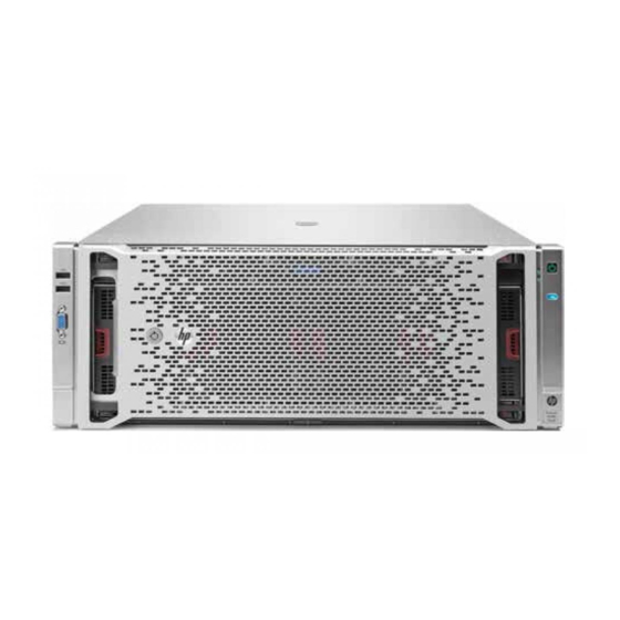
HP ProLiant DL580 Gen8 Server
Maintenance and Service Guide
Abstract
This document describes service procedures for the HP ProLiant DL580 Gen8 Server. This document is intended for experienced service technicians.
HP assumes that you are qualified in the servicing of computer equipment, are trained in recognizing hazards in products with hazardous energy
levels, and are familiar with weight and stability precautions for rack installations.
Part Number: 742022-002
October 2015
Edition: 2
Advertisement
Table of Contents

Related Manuals for HP ProLiant DL580 Gen8


Summary of Contents for HP ProLiant DL580 Gen8
- Page 1 This document describes service procedures for the HP ProLiant DL580 Gen8 Server. This document is intended for experienced service technicians. HP assumes that you are qualified in the servicing of computer equipment, are trained in recognizing hazards in products with hazardous energy levels, and are familiar with weight and stability precautions for rack installations.
- Page 2 © Copyright 2014, 2015 Hewlett-Packard Development Company, L.P. The information contained herein is subject to change without notice. The only warranties for HP products and services are set forth in the express warranty statements accompanying such products and services. Nothing herein should be construed as constituting an additional warranty. HP shall not be liable for technical or editorial errors or omissions contained herein.
-
Page 3: Table Of Contents
Contents Customer self repair ........................5 Parts only warranty service ......................... 5 Illustrated parts catalog ....................... 15 Mechanical components ........................... 15 System components ..........................18 Removal and replacement procedures ................... 24 Required tools ............................24 Safety considerations ..........................24 Preventing electrostatic discharge ....................24 Preparation procedures .......................... - Page 4 Mechanical specifications ........................87 Power supply specifications ........................87 HP 1200 W Common Slot Platinum Plus Hot-Plug Power Supply (94% efficiency) ........88 HP 1500 W Common Slot Platinum Plus Hot-Plug Power Supply (94% efficiency) ........88 Acronyms and abbreviations ......................89 Documentation feedback ......................
-
Page 5: Customer Self Repair
HP specifies in the materials shipped with a replacement CSR part whether a defective part must be returned to HP. In cases where it is required to return the defective part to HP, you must ship the defective part back to HP within a defined period of time, normally five (5) business days. The defective part must be returned with the associated documentation in the provided shipping material. - Page 6 HP sono realizzati con numerosi componenti che possono essere riparati direttamente dal cliente (CSR, Customer Self Repair). Se in fase di diagnostica HP (o un centro di servizi o di assistenza HP) identifica il guasto come riparabile mediante un ricambio CSR, HP lo spedirà direttamente al cliente per la sostituzione.
- Page 7 La mancata restituzione del componente può comportare la fatturazione del ricambio da parte di HP. Nel caso di riparazione da parte del cliente, HP sostiene tutte le spese di spedizione e resa e sceglie il corriere/vettore da utilizzare.
- Page 8 Si, durante la fase de diagnóstico, HP (o los proveedores o socios de servicio de HP) identifica que una reparación puede llevarse a cabo mediante el uso de un componente CSR, HP le enviará dicho componente directamente para que realice su sustitución. Los componentes CSR se clasifican en dos categorías:...
- Page 9 HP podrá cobrarle por el de sustitución. En el caso de todas sustituciones que lleve a cabo el cliente, HP se hará cargo de todos los gastos de envío y devolución de componentes y escogerá la empresa de transporte que se utilice para dicho servicio.
- Page 10 Opcional – Peças cujo reparo feito pelo cliente é opcional. Essas peças também são projetadas para o reparo feito pelo cliente. No entanto, se desejar que a HP as substitua, pode haver ou não a cobrança de taxa adicional, dependendo do tipo de serviço de garantia destinado ao produto.
- Page 11 No caso desse serviço, a substituição de peças CSR é obrigatória. Se desejar que a HP substitua essas peças, serão cobradas as despesas de transporte e mão-de-obra do serviço. Customer self repair 11...
- Page 12 Customer self repair 12...
- Page 13 Customer self repair 13...
- Page 14 Customer self repair 14...
-
Page 15: Illustrated Parts Catalog
Optional—Parts for which customer self repair is optional. These parts are also designed for customer self repair. If, however, you require that HP replace them for you, there may or may not be additional charges, depending on the type of warranty service designated for your product. - Page 16 Optional: Opcional—Peças cujo reparo feito pelo cliente é opcional. Essas peças também são projetadas para o reparo feito pelo cliente. No entanto, se desejar que a HP as substitua, pode haver ou não a cobrança de taxa adicional, dependendo do tipo de serviço de garantia destinado ao produto.
- Page 17 Illustrated parts catalog 17...
-
Page 18: System Components
735523-001 Optional Video/USB assembly (left ear bezel) 735525-001 Optional Power supplies — — a. HP 1200 W power supply, 230 V (94% 748896-001 Mandatory efficiency)** b. HP 1200 W power supply, 12 V (94% 660185-001 Mandatory efficiency)* c. HP 1500 W power supply (94%... - Page 19 Item Description Spare part Customer number self repair (on page 5) d. Intel Xeon E7-4870v2 734147-001 Optional (2.3GHz/15-core/30MB/130W) Processor* e. Intel Xeon E7-8857v2 734148-001 Optional (3.0GHz/12-core/30MB/130W) Processor* f. Intel Xeon E7-4860v2 734149-001 Optional (2.6GHz/12-core/30MB/130W) Processor* g. Intel Xeon E7-4850v2 734150-001 Optional (2.3GHz/12-core/24MB/105W) Processor* h.
- Page 20 Item Description Spare part Customer number self repair (on page 5) c. 900 GB SAS, SFF, 6G 10,000-rpm* 653971-001 Mandatory d. 600 GB SAS, SFF, 6G 10,000-rpm* 653957-001 Mandatory e. 450 GB SAS, SFF, 6G 10,000-rpm* 653956-001 Mandatory f. 300 GB SAS, SFF, 6G 10,000-rpm* 653955-001 Mandatory g.
- Page 21 Optional—Parts for which customer self repair is optional. These parts are also designed for customer self repair. If, however, you require that HP replace them for you, there may or may not be additional charges, depending on the type of warranty service designated for your product.
- Page 22 Optional: Opcional—Peças cujo reparo feito pelo cliente é opcional. Essas peças também são projetadas para o reparo feito pelo cliente. No entanto, se desejar que a HP as substitua, pode haver ou não a cobrança de taxa adicional, dependendo do tipo de serviço de garantia destinado ao produto.
- Page 23 Illustrated parts catalog 23...
-
Page 24: Removal And Replacement Procedures
Extend the server from the rack (on page 25). If you are performing service procedures in an HP, Compaq branded, telco, or third-party rack, you can use the locking feature of the rack rails to support the server and gain access to internal components. -
Page 25: Power Down The Server
If the rack environment, cabling configuration, or the server location in the rack creates awkward conditions, remove the server from the rack. • Remove the access panel (on page 29). If you are servicing internal components, remove the access panel. •... -
Page 26: Remove The Server From The Rack
Extend the server on the rack rails until the server rail-release latches engage. After performing the installation or maintenance procedure, slide the server into the rack by pressing the server rail-release latches. Remove the server from the rack WARNING: To reduce the risk of personal injury or equipment damage, be sure that the rack is adequately stabilized before extending a component from the rack. - Page 27 This symbol indicates that the component exceeds the recommended weight for one individual to handle safely. WARNING: To reduce the risk of personal injury or damage to the equipment, observe 32.18-52.87 kg local occupational health and safety requirements and guidelines for manual material 70.94-116.56 lb handling.
- Page 28 Top loading telescoping rails Front loading telescoping rails Removal and replacement procedures 28...
-
Page 29: Remove The Access Panel
Slide the server into the rack by pressing the server rail-release latches. Remove the access panel WARNING: To reduce the risk of personal injury from hot surfaces, allow the drives and the internal system components to cool before touching them. CAUTION: Do not operate the server for long periods with the access panel open or removed. -
Page 30: Processor Memory Drawer Shipping Screw Locations
Processor memory drawer shipping screw locations Two orange shipping screws secure the processor memory drawer in place during shipping. You must remove the screws to access the processor memory drawer. Retain the screws for future use. Remove the processor memory drawer WARNING: The processor memory drawer weighs more than 11.3 kg (25.0 lb). -
Page 31: Remove The Processor Memory Drawer Cover
Firmly holding the processor memory drawer, press the release buttons and then remove the drawer from the server. Remove the processor memory drawer cover Remove the processor memory drawer shipping screws, if installed. Retain the screws for future use ("Processor memory drawer shipping screw locations"... - Page 32 Disconnect each power cord from the power source. Disconnect each power cord from the server. Extend the server from the rack (on page 25). Remove the access panel (on page 29). Remove the processor memory drawer shipping screws, if installed. Retain the screws for future use ("Processor memory drawer shipping screw locations"...
-
Page 33: 4U Rack Bezel
4U rack bezel Remove the component as indicated. To replace the component, reverse the removal procedure. Remove the component as indicated. To replace the component, reverse the removal procedure. Removal and replacement procedures 33... -
Page 34: Drive Blank
Drive blank Remove the component as indicated. To replace the component, reverse the removal procedure. Drive To remove the component: Determine the status of the drive from the drive LED definitions ("Hot-plug drive LED definitions" on page 83). Back up all server data on the drive. Remove the drive. -
Page 35: Left Bezel (Usb/Video)
Prepare the drive. Install the drive. Determine the status of the drive from the drive LED definitions ("Hot-plug drive LED definitions" on page 83). Left bezel (USB/video) To remove the component: Power down the server (on page 25). Remove all power: Disconnect each power cord from the power source. -
Page 36: Usb/Video Cable/Discovery Services
Using a Torx T-10 screwdriver, remove the screws securing the bezel to the chassis. Then, remove the assembly from the server. Disconnect the cable from the bezel. To replace the component, reverse the removal procedure. USB/video cable/Discovery Services To remove the component: Power down the server (on page 25). -
Page 37: Right Bezel (Uid/Power/Sid)
Remove the access panel (on page 29). Remove the processor memory drawer (on page 30). Remove the SPI board (on page 31). Remove the left bezel ("Left bezel (USB/video)" on page 35). Disconnect the cable from the bezel. Disconnect the cable from the SPI board. To replace the component, reverse the removal procedure. -
Page 38: Uid/Power/Sid Cable
Disconnect each power cord from the server. Extend the server from the rack (on page 25). Remove the processor memory drawer (on page 30). Using a Torx T-10 screwdriver, remove the screws securing the bezel to the chassis. Then, remove the assembly from the server. -
Page 39: Hot-Plug Power Supply
The server supports up to four hot-plug power supplies. Install all power supplies to provide full redundancy. HP recommends installing redundant hot-plug power supplies in pairs. To confirm the redundancy of your configuration, see the HP power advisor at the HP website (http://www.hp.com/go/hppoweradvisor). -
Page 40: Power Supply Blank
Remove the failed power supply. To replace the component, reverse the removal procedure. Power supply blank Remove the component as indicated. To replace the component, reverse the removal procedure. Expansion board CAUTION: To prevent improper cooling and thermal damage, do not operate the server unless all expansion slots have either an expansion slot cover or an expansion board installed. -
Page 41: Expansion Slot Cover
Extend the server from the rack (on page 25). Remove the access panel (on page 29). Open the expansion board retainer. Disconnect any cables attached to the expansion board. Remove the retaining screw, if installed. Remove the expansion board. To replace the component, reverse the removal procedure. Expansion slot cover CAUTION: To prevent improper cooling and thermal damage, do not operate the server unless... -
Page 42: Expansion Board Guides
Power down the server (on page 25). Remove all power: Disconnect each power cord from the power source. Disconnect each power cord from the server. Extend the server from the rack (on page 25). Remove the access panel (on page 29). Open the expansion board retainer, and then remove the expansion slot cover. -
Page 43: Flash-Backed Write Cache Procedures
Remove the expansion board guide. To replace the component: Align the guide with the holes in the chassis, and then press up on the guide to snap it into place. Flash-backed write cache procedures Two types of procedures are provided for the FBWC option: •... -
Page 44: Removing The Cache Module
CAUTION: Do not detach the cable that connects the battery pack or capacitor pack to the cache module. Detaching the cable causes all data in the cache module to be lost. Removing the cache module WARNING: To reduce the risk of personal injury, electric shock, or damage to the equipment, remove the power cord to remove power from the server. -
Page 45: Removing The Capacitor Pack
If the existing cache module is connected to a capacitor pack, observe the FBWC module LEDs (on page 84): If the amber LED is flashing, data is trapped in the cache. Restore system power, and then restart this procedure from step 1. If the amber LED is not illuminated, remove the controller from the server, and then continue with the next step. - Page 46 CAUTION: In systems that use external data storage, be sure that the server is the first unit to be powered down and the last to be powered back up. Taking this precaution ensures that the system does not erroneously mark the drives as failed when the server is powered up. Extend the server from the rack (on page 25).
-
Page 47: Recovering Data From The Flash-Backed Write Cache
Set up a recovery server using an identical server model. Do not install any internal drives or FBWC in this server. (HP recommends this option.) Find a server that has enough empty drive bays to accommodate all the drives from the failed server and that meets all the other requirements for drive and array migration. -
Page 48: Removing The Fbwc Capacitor Pack Holder
Removing the FBWC capacitor pack holder WARNING: To reduce the risk of personal injury, electric shock, or damage to the equipment, remove the power cord to remove power from the server. The front panel Power On/Standby button does not completely shut off system power. Portions of the power supply and some internal circuitry remain active until AC power is removed. -
Page 49: Memory Cartridge
Remove the capacitor pack holder. To replace the component, reverse the removal procedure. Memory cartridge To remove the component: Power down the server (on page 25). Remove the processor memory drawer shipping screws, if installed. Retain the screws for future use ("Processor memory drawer shipping screw locations"... - Page 50 Remove the failed memory cartridge. Open the memory cartridge cover. Remove the DIMMs from the failed memory cartridge: Open the DIMM slot latches. Removal and replacement procedures 50...
- Page 51 Remove the DIMM. To replace the component: Install the DIMMs in the replacement memory cartridge: Open the DIMM slot latches. Install the DIMM. Close the memory cartridge cover. Removal and replacement procedures 51...
-
Page 52: Heatsink
Install the memory cartridge. Install the processor memory drawer cover. Install the processor memory drawer. Power up the server. Heatsink WARNING: To reduce the risk of personal injury from hot surfaces, allow the drives and the internal system components to cool before touching them. WARNING: To reduce the risk of personal injury, electric shock, or damage to the equipment, remove the power cord to remove power from the server. - Page 53 Remove the heatsink. To replace the component: Remove the thermal interface protective cover from the heatsink. CAUTION: To prevent the heatsink from tilting to one side during installation and removal procedures, use a diagonally opposite pattern (an “X” pattern) when loosening and tightening the two spring-loaded screws.
-
Page 54: Processor
Install the heatsink. Install the processor memory drawer cover. Install the processor memory drawer. Connect each power cord to the server. Connect each power cord to the power source. Power up the server. Processor WARNING: To reduce the risk of personal injury from hot surfaces, allow the drives and the internal system components to cool before touching them. - Page 55 Extend the server from the rack (on page 25). Remove the processor memory drawer (on page 30). Remove the processor memory drawer cover (on page 31). Remove the heatsink ("Heatsink" on page 52). Open each of the processor locking levers in the order indicated, and then open the processor retaining bracket.
- Page 56 To replace the component: Install the processor. Verify that the processor is fully seated in the processor retaining bracket by visually inspecting the processor installation guides on either side of the processor. THE PINS ON THE SYSTEM BOARD ARE VERY FRAGILE AND EASILY DAMAGED. CAUTION: THE PINS ON THE SYSTEM BOARD ARE VERY FRAGILE AND EASILY DAMAGED.
- Page 57 Remove the thermal interface protective cover from the heatsink. CAUTION: To prevent the heatsink from tilting to one side during installation and removal procedures, use a diagonally opposite pattern (an “X” pattern) when loosening and tightening the two spring-loaded screws. To prevent the screws from breaking off, do not over-tighten the screws.
-
Page 58: I/O Board
Power up the server. I/O board When replacing the I/O board, be sure the system maintenance switch settings on the replacement board match the settings on the old board. For more information, see "System maintenance switch (on page 78)." To remove the component: Power down the server (on page 25). -
Page 59: Top Sas Backplane
Remove the I/O board. To replace the component, reverse the removal procedure. Top SAS backplane CAUTION: To prevent damage to electrical components, take the appropriate anti-static precautions before beginning any system installation. Improper grounding can cause electrostatic discharge. To remove the component: Power down the server (on page 25). - Page 60 Extend the processor memory drawer approximately 2.54-5.1 cm (1-2 inches). Remove the SPI board (on page 31). Remove any drives installed in bays 6-10. Disconnect the data cable. Removal and replacement procedures 60...
-
Page 61: Power Daughter Board
Disconnect the power cable. Loosen the thumbscrews, and then remove the backplane. To replace the component, reverse the removal procedure. Power daughter board To remove the component: Power down the server (on page 25). Remove all power: Disconnect each power cord from the power source. Disconnect each power cord from the server. -
Page 62: Power Supply Backplane
Remove the access panel (on page 29). Disconnect the cables from the power daughter board. Remove the power daughter board. To replace the component, reverse the removal procedure. Power supply backplane To remove the component: Power down the server (on page 25). Remove all power: Disconnect each power cord from the power source. -
Page 63: Flexiblelom
Remove the backplane. To replace the component, reverse the removal procedure. FlexibleLOM To remove the component: Power down the server (on page 25). Remove all power: Disconnect each power cord from the power source. Disconnect each power cord from the server. Remove any attached network cables. -
Page 64: Battery
Extend the processor memory drawer approximately 2.54-5.1 cm (1-2 inches). Remove the SPI board (on page 31). Loosen the thumbscrew, and then remove the FlexibleLOM from the server. To replace the component, reverse the removal procedure. Battery If the server no longer automatically displays the correct date and time, you may need to replace the battery that provides power to the real-time clock. - Page 65 After replacing the battery, reconfigure the system through UEFI System Utilities. IMPORTANT: To avoid a mismatch between boot modes, HP recommends setting system maintenance switch 7 to the same BIOS boot mode the server is deployed in. Otherwise, the storage controller may not recognize the OS installed on the storage media.
-
Page 66: Hp Trusted Platform Module
If you suspect a TPM board failure, leave the TPM installed and remove the system board. Contact an HP authorized service provider for a replacement system board and TPM board. -
Page 67: Diagnostic Tools
• Simplified Chinese (http://www.hp.com/support/ProLiant_TSG_v1_sc) The HP ProLiant Gen8 Troubleshooting Guide, Volume II: Error Messages provides a list of error messages and information to assist with interpreting and resolving error messages on ProLiant servers and server blades. To view the guide, select a language: •... -
Page 68: Hp Insight Diagnostics
• Launching other pre-boot environments such as the Embedded UEFI Shell and Intelligent Provisioning For more information on the HP UEFI System Utilities, see the HP UEFI System Utilities User Guide on the HP website (http://www.hp.com/go/uefi/docs). Using HP UEFI System Utilities... -
Page 69: Flexible Boot Control
OS installation if the defaults are restored. To avoid this issue, use the User Defined Defaults feature in UEFI System Utilities to override the factory default settings. For more information, see the HP UEFI System Utilities User Guide for HP ProLiant Gen9 Servers on the HP website (http://www.hp.com/go/ProLiantUEFI/docs). -
Page 70: Embedded Uefi Shell
Embedded UEFI shell The system BIOS in all HP ProLiant DL580 Gen8 servers includes an embedded UEFI Shell in the ROM. The UEFI Shell environment provides an API, a command line prompt, and a set of CLIs that allow scripting, file manipulation, and system information. -
Page 71: Usb Support And Functionality
USB support and functionality USB support HP provides both standard USB 2.0 support and legacy USB 2.0 support. Standard support is provided by the OS through the appropriate USB device drivers. Before the OS loads, HP provides support for USB devices through legacy USB support, which is enabled by default in the system ROM. -
Page 72: Component Identification
Component identification Front panel components Item Description Drive bays 6-10* Systems Insight Display Fans 1-4 Drive bays 1-5 Discovery services connectors Video connector USB connectors (2) * Drives installed in these bays require the optional SAS backplane and cables. Component identification 72... -
Page 73: Front Panel Leds And Buttons
Front panel LEDs and buttons Item Description Status Power on/Standby button and Solid green = System on system power LED Flashing green (1 Hz/cycle per sec) = Performing power on sequence Solid amber = System in standby Off = No power present Health LED Solid green = Normal Flashing amber = System degraded... -
Page 74: Systems Insight Display
Systems Insight Display The Systems Insight Display LEDs represent the server and component layout. Item Description Power cap Green = System on or requesting power on Flashing amber = Power on denied Off = Standby Overtemperature Off = Normal Amber = Failed or missing component Amp status Off = No protection Green = Protection enabled... -
Page 75: Rear Panel Components
Rear panel components Item Description Expansion board slot 1 Expansion board slot 2 Expansion board slot 3 Expansion board slot 4 Expansion board slot 5 Expansion board slot 6 Expansion board slot 7 Expansion board slot 8 Expansion board slot 9 FlexibleLOM slot SPI board Power supply 1... -
Page 76: Power Supply Led
Power supply LED Fail LED-amber Power LED-green Front external health Status (Located on the SID) (Located on the power supply) Located on the front panel No AC power to power supply units Green AC present/Standby outputs Power supply DC outputs on and OK Amber (flashing) –... -
Page 77: I/O Board Components
I/O board components Item Description NMI jumper Slot 1 PCIe3 x16 (16, 8, 4, 2, 1) Slot 2 PCIe3 x16 (16, 8, 4, 2, 1) System maintenance switch Slot 3 PCIe3 x16 (16, 8, 4, 2, 1) Slot 4 PCIe3 x16 (8, 4, 2, 1) Slot 5 PCIe3 x16 (8, 4, 2, 1) Slot 6 PCIe3 x16 (16, 8, 4, 2, 1) Slot 7 PCIe3 x16 (8, 4, 2, 1) -
Page 78: System Maintenance Switch
UEFI System Utilities supersedes this switch. IMPORTANT: To avoid a mismatch between boot modes, HP recommends setting system maintenance switch 7 to the same BIOS boot mode the server is deployed in. Otherwise, the storage controller may not recognize the OS installed on the storage media. -
Page 79: Spi Board Components
SPI board components Item Description Top SAS backplane connector SAS cache module connector Systems Insight Display Power/UID connector Internal USB connector microSD card slot TPM connector Front video/USB connector Battery Internal USB connector Serial connector Video connector USB connectors (4) iLO connector FlexibleLOM port 1* FlexibleLOM port 2*... -
Page 80: Power Daughter Board Components
Power daughter board components Item Description Upper SAS backplane power connector I/O board auxiliary power connector I/O board auxiliary power connector I/O board auxiliary power connector I/O board auxiliary power connector I/O board auxiliary power connector I/O board auxiliary power connector Power backplane data connector Power backplane data connector I/O board power connector... -
Page 81: Processors And Memory Cartridges
Processors and memory cartridges The processor memory drawer contains 4 processor sockets and 8 memory cartridges. For DIMM numbering and installation guidelines, see the server user guide. Component identification 81... -
Page 82: Dimm Slot Locations
DIMM slot locations Each memory cartridge contains 12 DIMM slots. Install DIMMs in pairs in alphabetical order. For installation guidelines, see the server user guide. Drive bay numbering Drives installed in bays 6-10 require the optional SAS backplane. Component identification 82... -
Page 83: Hot-Plug Drive Led Definitions
Hot-plug drive LED definitions Item Status Definition Locate Solid blue The drive is being identified by a host application. Flashing blue The drive carrier firmware is being updated or requires an update. Activity ring Rotating green Drive activity No drive activity Do not remove Solid white Do not remove the drive. -
Page 84: Fbwc Capacitor Slots
FBWC capacitor slots Item Description Slots 2-4—Connect to optional SAS controllers Slot 1—Connects to the SPI board FBWC module LEDs The FBWC module has three single-color LEDs (one amber and two green). The LEDs are duplicated on the reverse side of the cache module to facilitate status viewing. 1 - Amber 2 - Green 3 - Green... -
Page 85: Fan Locations
1 - Amber 2 - Green 3 - Green Interpretation Flashing once The cache module is idle, and the capacitor pack is per second charging. The cache module is idle, and the capacitor pack is charged. The cache module is idle, the capacitor pack is charged, and the cache contains data that has not yet been written to the drives. -
Page 86: Cabling
Cabling Server cabling Item Description Standby power cable Power supply data cable Front video/USB cable Systems Insight Display cable Cabling 86... -
Page 87: Specifications
Depending on installed options, the server is configured with one of the following power supplies: • HP 1200 W Common Slot Platinum Plus Hot-Plug Power Supply (94% efficiency) (on page 88) • HP 1500 W Common Slot Platinum Plus Hot-Plug Power Supply (94% efficiency) (on page 88) For detailed power supply specifications, see the server QuickSpecs on the HP website (http://www.hp.com/go/hpsc). -
Page 88: Hp 1200 W Common Slot Platinum Plus Hot-Plug Power Supply (94% Efficiency)
HP 1200 W Common Slot Platinum Plus Hot-Plug Power Supply (94% efficiency) Specification Value Input requirements 100 VAC,100 to 120 VAC Rated input voltage 50 Hz to 60 Hz Rated input frequency 9.2 A at 100 VAC Rated input current 9.5 A at 110 to 120 VAC... -
Page 89: Acronyms And Abbreviations
Acronyms and abbreviations ABEND abnormal end Advanced Memory Protection Automatic Server Recovery Canadian Standards Association DDDC Double Device Data Correction electrostatic discharge FBWC flash-backed write cache International Electrotechnical Commission iLO 4 Integrated Lights-Out 4 Integrated Management Log keyboard, video, and mouse NVRAM nonvolatile memory Acronyms and abbreviations 89... - Page 90 PCIe Peripheral Component Interconnect Express PCI-X peripheral component interconnect extended power distribution unit port ID POST Power-On Self Test QuickPath Interconnect Reliability, Availability, Serviceability RBSU ROM-Based Setup Utility serial attached SCSI Secure Digital SDDC Single Device Data Correction small form factor Systems Insight Manager Scalable memory interfaces Acronyms and abbreviations 90...
- Page 91 HP Service Pack for ProLiant TMRA recommended ambient operating temperature Trusted Platform Module UEFI Unified Extensible Firmware Interface unit identification uninterruptible power system universal serial bus Version Control Agent Acronyms and abbreviations 91...
-
Page 92: Documentation Feedback
Documentation feedback HP is committed to providing documentation that meets your needs. To help us improve the documentation, send any errors, suggestions, or comments to Documentation Feedback (mailto:docsfeedback@hp.com). Include the document title and part number, version number, or the URL when submitting your feedback. -
Page 93: Index
69 hard drive LEDs 83 connectors 72 heatsink 52 CSR (customer self repair) 5 HP Insight Diagnostics 67, 68 customer self repair (CSR) 5 HP technical support 5 device numbers 82 I/O board 58 diagnostic tools 67, 68... - Page 94 Integrated Management Log (IML) 70 spare part numbers 15 internal USB functionality 71 specifications 87 specifications, environmental 87 specifications, power supply 87, 88 specifications, server 87 LEDs 83 SPI (System Peripheral Interface) board 31, 79 LEDs, drive 83 static electricity 24 LEDs, FBWC module 84 switch, system maintenance 78 LEDs, front panel 73, 83...