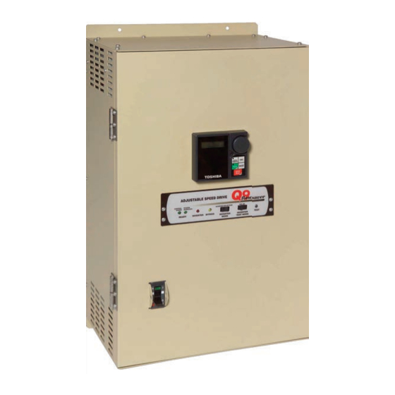
Toshiba Q9 Installation And Operation Manual
Flowsaver/bypass low voltage variable torque hvac inverter
Hide thumbs
Also See for Q9:
- Brochure & specs (8 pages) ,
- Installation and operation manual (233 pages)

Related Manuals for Toshiba Q9


Summary of Contents for Toshiba Q9
- Page 1 Q9 FlowSaver ASD/Bypass Box Installation and Operation Manual Document Number: 59492-002 Date: March, 2011 Phone: 800.894.0412 - Fax: 888.723.4773 - Web: www.ctiautomation.net - Email: info@ctiautomation.net...
- Page 2 Q9 FlowSaver/Bypass Installation and Operation Manual Document Number: 59492-002 Date: March, 2011 Phone: 800.894.0412 - Fax: 888.723.4773 - Web: www.ctiautomation.net - Email: info@ctiautomation.net...
- Page 3 LED display array to convey the system operational status. The EOI and the control panel provide superior monitoring and control of the Q9 F and allows AVER for easy-access programming for quick system changes when required.
- Page 4 Q9 F Adjustable Speed Drive system only. AVER This manual is to be used in conjunction with the Q9 ASD Installation and Operation Manual (P/N 59445). This manual provides information on the various features and functions of this powerful cost-saving device, including •...
- Page 5 ASD/Bypass Box AVER Please complete the Warranty Card supplied with your system and return it to Toshiba by prepaid mail. This will activate the 12 month warranty from the date of installation; but, shall not exceed 18 months from the shipping date.
-
Page 6: Table Of Contents
Using RCD Protection ......................9 EMC Installation Guidelines ....................9 General EMC Guidelines for Consideration ..............9 EMC Compliant Installation Guidelines................10 Q9 FLOWSAVER Theory of Operation ................11 Stage 1 Function .......................11 Stage 2 Function .......................11 Stage 3 Function .......................11 Stage 4 Function .......................12 System Protection ........................14... - Page 7 Startup and Test ......................23 I/O Monitoring and Control ....................24 I/O Terminal Descriptions ....................25 Q9 FLOWSAVER Monitoring/Control Interface ............28 Typical Q9 FLOWSAVER Connection Diagram ............29 Q9 FLOWSAVER Control Panel Features ..............33 Panel Item Descriptions ....................33 Enclosure Dimensional Information and Weights ..............35 Enclosure Dimensions/Weights ..................37...
-
Page 8: General Safety Information
The word CAUTION without the safety alert symbol indicates a potentially hazardous situation exists which, if not avoided or if instructions are not followed precisely, may result in equipment and property damage. Q9 FlowSaver Installation and Operation Manual Phone: 800.894.0412 - Fax: 888.723.4773 - Web: www.ctiautomation.net - Email: info@ctiautomation.net... -
Page 9: Special Symbols
Inspections may be required before and after moving installed equipment. • Keep the equipment in an upright position. • Contact Toshiba’s Customer Support Center to report discrepancies or for assistance if required. Q9 FlowSaver Installation and Operation Manual Phone: 800.894.0412 - Fax: 888.723.4773 - Web: www.ctiautomation.net - Email: info@ctiautomation.net... -
Page 10: Qualified Personnel
NFPA 70E for additional safety requirements). Qualified Personnel shall: • Have read the entire installation and operation manual. • Be familiar with the construction and function of the Q9 F , the equipment being driven, AVER and the hazards involved. •... -
Page 11: Installation Precautions
• Allow proper clearance spaces for installation. Do not obstruct the ventilation openings. Refer to the section titled Installation and Connections of the Q9 ASD Installation and Operation Manual (P/N 59445) for further information on installation and ventilation requirements. Mounting •... -
Page 12: Conductors And Grounding
(refer to the NEC Article 310 adjustment factors). • Ensure that the 3-phase input power is Not connected to the output of the Q9 F . This will AVER damage the system and may cause injury to personnel. -
Page 13: Protection
Emergency Off braking function is to remove output power from the drive in the event of an emergency. A supplemental braking system may also be engaged in the event of an emergency. For further information on braking systems, see DC Injection Braking in the Q9 ASD Installation and Operation Manual. -
Page 14: System Setup Requirements
• DO NOT attempt to configure or connect the DBR function to the Q9 ASD. • Attempts to configure or adapt the Q9 ASD to use the Dynamic Braking function may result in system damage or injury to personnel. •... -
Page 15: Operational And Maintenance Precautions
Charge LED. Wait for at least the minimum time indicated on the enclosure- mounted label and ensure that the Charge LED has gone out before opening the door of the Q9 once the power has been turned off. -
Page 16: Ce Compliance Requirements
European market is required to comply to the European Community directive on electromagnetic compatibility (EMC). The following instructions provide a means of compliance for the Q9 . A Technical Construction File (TCF) indicates the rationale used to declare compliance and AVER is on file at Toshiba International Corporation, Houston, Texas, U.S.A. -
Page 17: Emc Compliant Installation Guidelines
Q94220I FN258-42 BYP4-100E FN258-130 FN258-100 Q92270I Q94270I BYP4-125E FN258-180 FN258-55 Q92330I FN258-130 Q94330I BYP4-160E FS5236-300 Q92400I FN258-180 Q94400I FN258-75 BYP2-100E FN258-130 BYP2-125E FN258-180 Q9 FlowSaver Installation and Operation Manual Phone: 800.894.0412 - Fax: 888.723.4773 - Web: www.ctiautomation.net - Email: info@ctiautomation.net... -
Page 18: Q9 Flowsaver Theory Of Operation
ASD systems are designed with the AVER ASD component and the Bypass Box provided and mounted as separate items (e.i., the ASD is sold separately). The same is true for the 400-volt 50 – 100 HP Q9 ASD Systems. AVER The Integrated Enclosure and the BYP Series systems operate in the same manner —... -
Page 19: Stage 4 Function
(reversible means that only the opposite function is available once reaching the fully opened or closed position). Q9 FlowSaver Installation and Operation Manual Phone: 800.894.0412 - Fax: 888.723.4773 - Web: www.ctiautomation.net - Email: info@ctiautomation.net... - Page 20 Figure 1. Simplified depiction (Ladder Logic) of the Q9 F Bypass operation. AVER Q9 FlowSaver Installation and Operation Manual Phone: 800.894.0412 - Fax: 888.723.4773 - Web: www.ctiautomation.net - Email: info@ctiautomation.net...
-
Page 21: System Protection
The short-circuit protection, which is provided by hardware and software, disables the system in the event of a fault. The installer is to provide input fuses for the 230-volt Q9 F ASDs. The 460-volt AVER Q9 F ASDs are equipped with internal primary power input fuses as a standard feature. -
Page 22: Motor Protection
The MCP that is used on the L1, L2, and L3 input power lines has a Shunt Trip feature which may be used to further enhance the system protection function of the Q9 F . The Shunt Trip feature may AVER be connected such that the L1, L2, and L3 MCP may be opened by a state change of the LS switch. -
Page 23: Motor Circuit Protector Adjustment And Setting
Overload settings are application-specific and should be set and/or adjusted by Qualified Personnel ONLY (see Qualified Personnel on pg. Figure 3. MCP Adjustment. Set to minimum at the factory. Application-specific adjustment is required. Q9 FlowSaver Installation and Operation Manual Phone: 800.894.0412 - Fax: 888.723.4773 - Web: www.ctiautomation.net - Email: info@ctiautomation.net... -
Page 24: Overload Circuit Protector Adjustment And Setting
The contacts may be used with ancillary circuitry to annunciate an overload trip or to control other system features. Q9 FlowSaver Installation and Operation Manual Phone: 800.894.0412 - Fax: 888.723.4773 - Web: www.ctiautomation.net - Email: info@ctiautomation.net... -
Page 25: Q9 Flowsaver Installation
Control Signal Isolation Interface problems may occur when some ASDs are used in conjunction with process controllers. Signal isolation may be required to prevent controller and/or ASD malfunctions. The Q9 F AVER option, the ASD-ISO-1, provides isolation of the Control Board output circuit from the AM/FM output and from the I input (for further information on the ASD-ISO-1 option contact Toshiba’s... -
Page 26: Mounting And Connections
The Q9 F may be set up initially by performing a few simple system configuration AVER connections and settings. To operate properly, the Q9 F must be securely mounted and AVER connected to a power source (3-phase AC input at the L1, L2, and L3 terminals). The control terminals... -
Page 27: Mounting The Bypass Box
Mounting the Bypass Box The Q9 ASD and the Bypass Box of the BYP Series are provided as separate items — the two are not shipped from the factory electrically or mechanically connected. The Q9 ASD and the Bypass Box are installed independently and then connected together. -
Page 28: Connecting The Bypass Box
Terminal Specifications on pg. Connect the Q9 ASD to the Bypass Box as follows: Connect the L1, L2, and L3 terminals of the Q9 ASD to the L1, L2, and L3 terminals of the Bypass Box, respectively, via terminal block PDB1. - Page 29 AVER Note: The connection diagram of Figure 5 applies to all BYP Series Q9 FlowSaver systems (i.e., EA, EC, and EE) — EE type shown. Q9 FlowSaver Installation and Operation Manual Phone: 800.894.0412 - Fax: 888.723.4773 - Web: www.ctiautomation.net - Email: info@ctiautomation.net...
-
Page 30: Startup And Test
With the previous checks confirmed, ensure that the direction of the motor rotation in the Bypass mode and in the ASD-driven mode is consistent. • Ensure that all personnel are clear of the motor and the motor-driven equipment. Q9 FlowSaver Installation and Operation Manual Phone: 800.894.0412 - Fax: 888.723.4773 - Web: www.ctiautomation.net - Email: info@ctiautomation.net... -
Page 31: I/O Monitoring And Control
ASD or of the magnitude of the function assigned to this terminal. — Return for all input and output terminals (Do Not connect to Earth Gnd). Q9 FlowSaver Installation and Operation Manual Phone: 800.894.0412 - Fax: 888.723.4773 - Web: www.ctiautomation.net - Email: info@ctiautomation.net... -
Page 32: I/O Terminal Descriptions
Emergency Off is to remove power from the output of the ASD and may apply a supplemental braking system using the method selected at the Emg Off Mode selection parameter (F603). This input terminal may be programmed to any of the functions that are listed in the Q9 ASD Installation and Operation Manual. - Page 33 FLC — FLC is the common leg of a single-pole double-throw form C relay. The FL relay is the Fault Relay by default, but may be programmed to any of the selections listed in the Q9 ASD Installation and Operation Manual.
- Page 34 Output Frequency of the Q9 ASD (or the function assigned to this terminal). The Voltage/Current output selection is performed at F681. This output terminal may be programmed to provide an output that is a function of any of the functions listed in the Q9 ASD Installation and Operation Manual.
-
Page 35: Q9 Flowsaver Monitoring/Control Interface
Q9 F Monitoring/Control Interface AVER The Terminal Board (P/N 53750) serves as a monitoring and control interface of the Q9 F AVER The Terminal Board receives input from ancillary devices, transducers, or from the user via the EOI. The Terminal Board also provides output signals that may be used to control ancillary devices, close/ open a contact, annunciate, or monitor system variables. -
Page 36: Typical Q9 Flowsaver Connection Diagram
Typical Q9 F Connection Diagram AVER The three expanded depictions of the Q9 F systems are shown in figures 8, 9, and 10. AVER Figure 7. Q9 F general connection diagram. AVER Note: When connecting multiple wires to the PA, PB, PC, or PO terminals, do not connect a solid wire and a stranded wire to the same terminal. - Page 37 Figure 8. Q9 F -IA typical connection diagram — No Bypass Contactors. AVER Q9 FlowSaver Installation and Operation Manual Phone: 800.894.0412 - Fax: 888.723.4773 - Web: www.ctiautomation.net - Email: info@ctiautomation.net...
- Page 38 Figure 9. Q9 F -IC typical connection diagram — Two-Contactor Bypass. AVER Q9 FlowSaver Installation and Operation Manual Phone: 800.894.0412 - Fax: 888.723.4773 - Web: www.ctiautomation.net - Email: info@ctiautomation.net...
- Page 39 Figure 10. Q9 F -IE typical connection diagram — Three-Contactor Bypass. AVER Q9 FlowSaver Installation and Operation Manual Phone: 800.894.0412 - Fax: 888.723.4773 - Web: www.ctiautomation.net - Email: info@ctiautomation.net...
-
Page 40: Q9 Flowsaver Control Panel Features
(A, C, or E typeforms). Panel A is used as a cover and has no active features. Panels C and E provide the user with access to the Q9 F monitoring and control features. - Page 41 Inverter Test Mode switch (when on) closes the 1M contactor (via K1) to test the ASD section of the system without providing an ASD output to the connected motor. Test LED (LED 1) — On during Inverter Test Mode operation. Q9 FlowSaver Installation and Operation Manual Phone: 800.894.0412 - Fax: 888.723.4773 - Web: www.ctiautomation.net - Email: info@ctiautomation.net...
-
Page 42: Enclosure Dimensional Information And Weights
Bypass Box (only) Part Numbering Convention Figure 13. AVER Note: The Type 1 enclosed versions of the Q9 F meet or exceed the specification AVER UL 1995, the Standard for Heating and Cooling Equipment, and complies with the applicable requirements for installation in a compartment handling conditioned air. - Page 43 Figure 14. Typical Q9 F components. L-*OW AVER Note: Size 1 shown. Q9 FlowSaver ASD Installation and Operation Manual Phone: 800.894.0412 - Fax: 888.723.4773 - Web: www.ctiautomation.net - Email: info@ctiautomation.net...
-
Page 44: Enclosure Dimensions/Weights
ASD Series Enclosure Size 1 (inches/mm). AVER Shipping Model Weight Number Q9 Approx. (Lbs.) 2015 2025 2035 2055 2080 4015 4025 4035 4055 4080 4110 4160 Q9 FlowSaver ASD Installation and Operation Manual Phone: 800.894.0412 - Fax: 888.723.4773 - Web: www.ctiautomation.net - Email: info@ctiautomation.net... - Page 45 ASD Series Enclosure Size 2 (inches/mm). AVER Shipping Model Weight Number Q9 Approx. (Lbs.) 2110 2160 2220 2270 4220 4270 4330 4400 Q9 FlowSaver ASD Installation and Operation Manual Phone: 800.894.0412 - Fax: 888.723.4773 - Web: www.ctiautomation.net - Email: info@ctiautomation.net...
- Page 46 Part number suffix = (R) + 3, 5, or D (i.e., R3, R5, or RD). Figure 12. on pg. 35 for more on the part numbering convention. Q9 FlowSaver ASD Installation and Operation Manual Phone: 800.894.0412 - Fax: 888.723.4773 - Web: www.ctiautomation.net - Email: info@ctiautomation.net...
- Page 47 32.10/815 30.12/765 31.23/793 BYP4-080-EXRX 5.30/135 BYP4-100-EX BYP4-100-EXRX 37.10/942 35.12/892 36.23/920 BYP4-125-EX 32.10/815 30.12/765 31.23/793 12.50/318 4.41/112 6.89/175 BYP4-125-EXRX 37.10/942 35.12/892 36.23/920 BYP4-160-EX Q9 FlowSaver ASD Installation and Operation Manual Phone: 800.894.0412 - Fax: 888.723.4773 - Web: www.ctiautomation.net - Email: info@ctiautomation.net...
-
Page 48: Cable/Terminal Specifications
– Q94110 – Q94160 (2-core shield) (3-core shield) – Q94220 Q94270 – Q94330 Q94400 – – Q94500 Q94600 – 8 – 3/0 Q9 FlowSaver ASD Installation and Operation Manual Phone: 800.894.0412 - Fax: 888.723.4773 - Web: www.ctiautomation.net - Email: info@ctiautomation.net... - Page 49 6 – 300 – BYP4-070 – – (2-core shield) (3-core shield) BYP4-080 – BYP4-100 – BYP4-125 – – BYP4-160 6 – 300 Q9 FlowSaver ASD Installation and Operation Manual Phone: 800.894.0412 - Fax: 888.723.4773 - Web: www.ctiautomation.net - Email: info@ctiautomation.net...
-
Page 50: Current/Voltage Specifications
44.0 A Q94400 40.0 40.0/22.0 52.0 A 57.2 A Q94500 50.0 50/30.0 65.0 A 71.5 A Q94600 60.0 60/37.0 77.0 A 84.7 A Q9 FlowSaver ASD Installation and Operation Manual Phone: 800.894.0412 - Fax: 888.723.4773 - Web: www.ctiautomation.net - Email: info@ctiautomation.net... - Page 51 Q9U4750 69.9 75/56 96.0 A 105.6 A BYP4-125 Q9U410K 93.3 100/74.6 124.0 A 136.4 A BYP4-160 Q9U412K 125/93.3 156.0 A 171.6 A Q9 FlowSaver ASD Installation and Operation Manual Phone: 800.894.0412 - Fax: 888.723.4773 - Web: www.ctiautomation.net - Email: info@ctiautomation.net...
- Page 52 Installation Notes, 18 Damper Response, 12, 24 DBR function, 7 Installation Precautions, 4 Default Term. Setting, 24 Introduction, 3 Discrete Input, 24 INV, 11 Q9 FlowSaver Installation and Operation Manual Phone: 800.894.0412 - Fax: 888.723.4773 - Web: www.ctiautomation.net - Email: info@ctiautomation.net...
- Page 53 L1, L2, and L3 connections, 12 Power Connections, 20 V terminal, 26 PP, 24, 27 Voltage Specifications, 43 Q9 Flow Saver Connection Diagram, 29 Warranty Card, 6 Q9 Flow Saver Enclosure, 36 Q9 Flow Saver-A, 30 Weights, 35 Q9 FlowSaver Installation and Operation Manual Phone: 800.894.0412 - Fax: 888.723.4773 - Web: www.ctiautomation.net - Email: info@ctiautomation.net...