
Related Manuals for Toshiba SD-22VB

Summary of Contents for Toshiba SD-22VB
- Page 1 FILE NO. 810-200213 SERVICE MANUAL DVD VIDEO PLAYER & VIDEO CASSETTE RECORDER SD-22VB SD-22VE SD-22VL OCT., 2002...
-
Page 2: Safety Precautions
Power consumption: Operation: 23W Stand by: 7W Hi-Fi VIDEO Weight: 4.5 kg Dimensions: Width : 430 mm SD-22VB CASSETTE Height : 99 mm Depth : 314.5 mm VIDEO: 1 Vp-p, 75 Ω RECORDER Input Level: SCART-socket: AUDIO: 500 mV, 50 k Ω... -
Page 3: Table Of Contents
Features Contents Video Cassette Recorder • Digital AUTO Tracking (ATR Before using your unit Disc playback operation Function) • High Quality (HQ) Images Safety Precautions ........... 2 DISC ............... 36 • Repeat Playback • On-Screen Displays (OSD) Features ............4 Setting setup language ........ -
Page 4: Remote Control
Remote control Remote control How to install the batteries Page Switch to operate VCR Use micro batteries type AAA. Switch to operate DVD On/Standby Slide the battery compartment Install two "AAA" batteries (supplied), Replace the compartment cover in the direction of the paying attention to the polarity cover. -
Page 5: Tuning The Tv Stations And Setting The Time And Date Automatically
Tuning the TV Stations and Setting the Time and Playback connection Date Automatically Plug your DVD/VCR into the mains sup- Preparation Connect to a Stereo Amplifier with Audio Output ply and it will start to automatically tune • Make sure that your DVD/VCR is connected properly to the TV. If your DVD/VCR is connected to a stereo amplifier, the video soundtrack can output through the loudspeakers of •... -
Page 6: Tuning The Tv Stations Manually
Tuning the TV Stations Manually ® Setting the VIDEO Plus + Channel Number (Guide CH) This VCR has one built-in tuner to Preparation The TV stations must be stored according Preparation receive broadcasts. Before you to the tuning guide given on page 13, •... -
Page 7: Special Playback/Playback Sharpness/Skip Search
Special playback/Playback sharpness/Skip Search Repeat Playback To set the Repeat function If the Repeat function is switched Special playback Playback sharpness on, the playback will continue until Preparation it reaches the tape-end and then Picture Search Adjust the sharpness of playback picture during •... -
Page 8: Recording
Recording a TV Programme Recording a TV Programme Preparation: Recording with a SCART Lead: Press TV/VCR until "VCR" appears on the display. Select • Turn on the TV, and select the VCR channel on TV. the program on the DVD/VCR you want to record. This You can record a programme using •... -
Page 9: Video Plus+ Recording
VIDEO Plus+ Recording Timer Recording Manually The built-in timer allows unattended Preparation If you have selected Daily or Weekly in step 3, then you recording of up to 8 programmes • Turn on the TV and select the VCR channel on TV. can select a recording date again. -
Page 10: Nicam Stereo Recording And Playback
NICAM Stereo Recording and Playback NICAM Stereo Recording and Playback This DVD/VCR is capable of recording Preparation: Playback sound in Hi-Fi system. The recording • Turn ON the TV and select the VCR channel on TV. Use AUDIO to select under stereo/mono or bilingual playback. will be performed automatically. -
Page 11: Disc
Disc Setting setup language The setup language can be selected. This unit applies to DVD discs from Region 2 only. Preparation: The loaded Disc (DVD, Video-CD, Audio-CD and MP3-CD) will be recognized automatically. • Turn ON the TV and set to the video input mode. The suitable Disc-formats are: DVD, CD-R and CD-RW. -
Page 12: Dvd Picture Signal Selection/Zooming
DVD Picture Signal Selection/Zooming Repeat playback Preparation: Preparation: You can select the output signal of • Turn ON the TV and set to the video input mode. • Turn ON the TV and set to the video input mode. DVD playback picture to the TV •... -
Page 13: Changing Soundtrack Language / Changing Subtitles Language
Changing soundtrack language / Changing Subtitles language Changing angles / Title selection / DVD menu Preparation: Preparation: • Turn ON the TV and set to the video input mode. • Turn ON the TV and set to the video input mode. •... -
Page 14: Setting Menu Language
Setting menu language Setting audio soundtrack language You can select the language of the Preparation: The same audio soundtrack language Preparation: disc menu messages of DVDs. • Turn ON the TV and set to the video input mode. can always be selected by your unit •... -
Page 15: Setting Audio
Setting Audio Setting Operation Preparation: Preparation: • Turn ON the TV and set to the video input mode. • Turn ON the TV and set to the video input mode. • Press DVD to select the DVD mode. (The DVD •... -
Page 16: Status Display Of Disc
Status display of Disc Table of languages You can view information on the operation status and access and settings. Enter the appropriate code for the initial settings"Menu", "Audio" and/or "Subtitle" (see pages 48~50). With each press of DISPLAY, the status of the disc will appear on the screen and change as follows. Abbreviation Language Abbreviation... - Page 17 IMPORTANT WARNING CAUTION: DVD PLAYER IS A CLASS 1 LASER PRODUCT. HOWEVER THIS PLAYER USES A VISIBLE LASER BEAM WHICH COULD CAUSE HAZARDOUS RADIATION EXPOSURE IF DIRECTED. BE SURE TO OPERATE THE PLAYER CORRECTLY AS INSTRUCTED. THE FOLLOWING CAUTION LABEL IS LOCATED ON THE REAR PANEL OF THE PLAYER. CLASS 1 LASER PRODUCT (Printed on the Rear Panel)
-
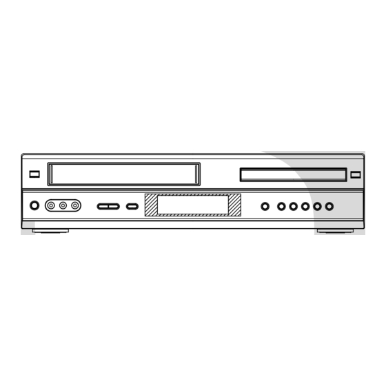
Page 18: Front
TAPE REMOVAL METHOD AT NO POWER SUPPLY Remove the Top Cabinet, Front Cabinet and DVD Block and the Fig. 1 below can be seen. (Refer to item 1 of the DISASSEMBLY INSTRUCTIONS.) Remove one screw of the Loading Motor from the insert hole for screw driver and remove the Loading Motor. - Page 19 CONTENTS • OWNER'S MANUAL A1-1 IMPORTANT WARNING ......................A1-1 SERVICING NOTICES ON CHECKING ..................A1-1 HOW TO ORDER PARTS ......................A1-2 TAPE REMOVAL METHOD AT NO POWER SUPPLY ............A1-2 DISC REMOVAL METHOD AT NO POWER SUPPLY ............. A1-2 PARENTAL CONTROL-RATING LEVEL .................. A2-1 CONTENTS ..........................
-
Page 20: System
GENERAL SPECIFICATIONS (SD-22VB) Outline of the product DVD VIDEO PLAYER & VHS Player / Recorder DVD System Color System Disc DVD, CD-DA, CD-R/RW, VIDEO CD Disc Diameter 120 mm , 80 mm Deck Disc Loading System Front Disc Loading Motor... - Page 21 GENERAL SPECIFICATIONS (SD-22VB) Signal Video Signal Output Level 1 V p-p/75 ohm (DVD,VCR) S/N Ratio (Weighted) 65 dB(DVD) 53 dB(VCR) Horizontal Resolution 500 Lines (DVD) 240 Lines(VCR at SP) RGB Signal Output Level 0.7V p-p / 75 ohm Audio Signal...
-
Page 22: System
GENERAL SPECIFICATIONS (SD-22VB) On Screen Menu Display(VCR) Menu Type Character Timer Rec Set VCR Extension Auto Repeat On/Off Scene Repeat Audio Dubbing VCR Set-Up NICAM Auto/Off Audio Mix On/Off Color System Sharpness BBE On/Off CH Set-Up CH Tuning Auto Tuning... - Page 23 GENERAL SPECIFICATIONS (SD-22VB) G-13 Display DISPLAY DISPLAY type Fluorescent Indicator Clock/Counter,CH,Timer Rec,OTR, Play Rec,FF(Cue),Rew(Rev),Stop,ATR,Eject Yes (24h) Clock Counter Yes (hour:min:sec) DVD Yes (hour:min:sec) CD Yes (min:sec) Counter Remain Play Stop FF / Cue REW /Review Pause/Still T-Rec Chapter TITLE TRACK...
- Page 24 GENERAL SPECIFICATIONS (SD-22VB) G-14 Remote Unit RC-FW Control Glow in Dark Remocon Power Source Voltage(D.C) UM size x pcs UM-4 x 2 pcs Total Keys 48 Keys Keys Power 0/AV DVD MENU MEMORY RETURN OPEN/CLOSE CLOCK / COUNTER SUB TITLE/ATR...
- Page 25 GENERAL SPECIFICATIONS (SD-22VB) G-15 Features Auto Power Off (DVD) Parental Lock Video CD Playback MP3 Playback Digital Out Dolby Digital MPEG1,MPEG2 Down Mix Out (Dolby Digital, MPEG1,MPEG2) Self Diagnostic Spatializer (N-2-2) Screen Saver Frame Advance One Touch Replay (10 Sec reverse)
-
Page 26: Front
GENERAL SPECIFICATIONS (SD-22VB) G-17 Interface Switch Front Power Play Eject (VCR) Stop Rec/OTR Open/Close (DVD) CH + CH - FF/ Search(>>) Rew/Search(<<) Still/Pause Shuttle(Search/REV/FWD) DVD/VCR Input Select Main Power SW Rear Attenuator Video/RGB Selector RF Out(Slide SW) Main Power SW... -
Page 27: System
GENERAL SPECIFICATIONS (SD-22VE) Outline of the product DVD VIDEO PLAYER & VHS Player / Recorder DVD System Color System Disc DVD, CD-DA, CD-R/RW, VIDEO CD Disc Diameter 120 mm , 80 mm Deck Disc Loading System Front Disc Loading Motor 3 Motors Pick up 1-Lens 2-Beams System... - Page 28 GENERAL SPECIFICATIONS (SD-22VE) Operating Humidity Less then 80% RH Signal Video Signal Output Level 1 V p-p/75 ohm (DVD,VCR) S/N Ratio (Weighted) 65 dB(DVD) 53 dB(VCR) Horizontal Resolution 500 Lines (DVD) 240 Lines(VCR at SP) RGB Signal Output Level 0.7V p-p / 75 ohm Audio Signal Input Level Microphone Input Level Line...
-
Page 29: System
GENERAL SPECIFICATIONS (SD-22VE) On Screen Menu Display(VCR) Menu Type Character Timer Rec Set VCR Extension Auto Repeat On/Off Scene Repeat Audio Dubbing VCR Set-Up NICAM Auto/Off Audio Mix On/Off Color System Sharpness BBE On/Off CH Set-Up CH Tuning Auto Tuning CH Mapping Guide CH Set Pin Code Registration... - Page 30 GENERAL SPECIFICATIONS (SD-22VE) G-14 Remote Unit RC-FW Control Glow in Dark Remocon Power Source Voltage(D.C) UM size x pcs UM-4 x 2 pcs Total Keys 48 Key Keys Power 0/AV DVD MENU MEMORY RETURN OPEN/CLOSE CLOCK / COUNTER SUB TITLE/ATR ANGLE/COUNTER RESET ZERO RETURN PLAY MODE/SPEED...
- Page 31 GENERAL SPECIFICATIONS (SD-22VE) G-15 Features Auto Power Off (DVD) Parental Lock Video CD Playback MP3 Playback Digital Out Dolby Digital MPEG1,MPEG2 Down Mix Out (Dolby Digital, MPEG1,MPEG2) Self Diagnostic Spatializer (N-2-2) Screen Saver Frame Advance One Touch Replay (10 Sec reverse) Features Auto Head Cleaning (VCR)
-
Page 32: Front
GENERAL SPECIFICATIONS (SD-22VE) G-17 Interface Switch Front Power Play Eject (VCR) Stop Rec/OTR Open/Close (DVD) CH + CH - FF/ Search(>>) Rew/Search(<<) Still/Pause Shuttle(Search/REV/FWD) DVD/VCR Input Select Main Power SW Rear Attenuator Video/RGB Selector RF Out(Slide SW) Main Power SW Volume Phones Volume Mic Volume... -
Page 33: On/Standby
GENERAL SPECIFICATIONS (SD-22VL) Outline of the product DVD VIDEO PLAYER & VHS Player / Recorder DVD System Color System Disc DVD, CD-DA, CD-R/RW, VIDEO CD Disc Diameter 120 mm , 80 mm Deck Disc Loading System Front Disc Loading Motor 3 Motors Pick up 1-Lens 2-Beams System... - Page 34 GENERAL SPECIFICATIONS (SD-22VL) Operating Humidity Less than 80% RH Signal Video Signal Output Level 1 V p-p/75 ohm (DVD,VCR) S/N Ratio (Weighted) 65 dB(DVD) 53 dB(VCR) Horizontal Resolution 500 Lines (DVD) 240 Lines(VCR at SP) RGB Signal Output Level 0.7V p-p / 75 ohm Audio Signal Input Level Microphone Input Level Line...
-
Page 35: System
GENERAL SPECIFICATIONS (SD-22VL) On Screen Menu Display(VCR) Menu Type Character Timer Rec Set VCR Extension Auto Repeat On/Off Scene Repeat Audio Dubbing VCR Set-Up NICAM Auto/Off Audio Mix On/Off Color System Sharpness BBE On/Off CH Set-Up CH Tuning Auto Tuning CH Mapping Guide CH Set Pin Code Registration... - Page 36 GENERAL SPECIFICATIONS (SD-22VL) G-14 Remote Unit RC-FW Control Glow in Dark Remocon Power Source Voltage(D.C) UM size x pcs UM-4 x 2 pcs Total Keys 48 Keys Keys Power 0/AV DVD MENU MEMORY RETURN OPEN/CLOSE CLOCK / COUNTER SUB TITLE/ATR ANGLE/COUNTER RESET ZERO RETURN PLAY MODE/SPEED...
- Page 37 GENERAL SPECIFICATIONS (SD-22VL) G-15 Features Auto Power Off (DVD) Parental Lock Video CD Playback MP3 Playback Digital Out Dolby Digital MPEG1,MPEG2 Down Mix Out (Dolby Digital, MPEG1,MPEG2) Self Diagnostic Spatializer (N-2-2) Screen Saver Frame Advance One Touch Replay (10 Sec reverse) Features Auto Head Cleaning (VCR)
-
Page 38: Front
GENERAL SPECIFICATIONS (SD-22VL) G-17 Interface Switch Front Power Play Eject (VCR) Stop Rec/OTR Open/Close (DVD) CH + CH - FF/ Search(>>) Rew/Search(<<) Still/Pause Shuttle(Search/REV/FWD) DVD/VCR Input Select Main Power SW Rear Attenuator Video/RGB Selector RF Out(Slide SW) Main Power SW Volume Phones Volume Mic Volume... -
Page 39: Notes
DISASSEMBLY INSTRUCTIONS REMOVAL OF MECHANICAL PARTS AND P.C. BOARDS 1-1: TOP CABINET AND FRONT CABINET (Refer to Fig. 1-1) Remove the 5 screws 1. Remove the Top Cabinet in the direction of arrow (A). Disconnect the following connectors: (CP681, CP601). Unlock the 8 supports 2. - Page 40 DISASSEMBLY INSTRUCTIONS 1-5: VCR DECK (Refer to Fig. 1-5) 1-7: POWER PCB (Refer to Fig. 1-7) Unlock the 2 supports 1 and remove the Top Holder. Remove the 3 screws 1. Remove the 3 screws 2. Remove the Power PCB in the direction of arrow. Disconnect the following connectors: (CP101, CP102, CP103 and CP3001).
-
Page 41: Front
DISASSEMBLY INSTRUCTIONS 2. REMOVAL OF DECK PARTS NOTE In case of the Locker R installation, check if the two 2-1: TOP BRACKET (Refer to Fig. 2-1) positions of Fig.2-3-B are correctly locked. Extend the 2 supports 1. When you install the Cassette Side R, be sure to move Slide the 2 supports 2 and remove the Top Bracket. - Page 42 DISASSEMBLY INSTRUCTIONS 2-6: LOADING MOTOR/WORM (Refer to Fig. 2-6-A) 2-7: TENSION ASS'Y (Refer to Fig. 2-7-B) Remove the screw 1. Turn the Pinch Roller Cam clockwise so that the Remove the Loading Motor. Tension Holder hook is set to the position of Fig. 2-7-A Remove the Worm.
- Page 43 DISASSEMBLY INSTRUCTIONS 2-8: T BRAKE ARM/T BRAKE BAND (Refer to Fig. 2-8-A) Remove the T Brake Spring. Idler Gear Turn the T Brake Arm clockwise and bend the hook Idler Arm Ass'y section to remove it. Unlock the 2 supports 1 and remove the T Brake S Reel Band.
-
Page 44: Front
DISASSEMBLY INSTRUCTIONS 2-10: CASSETTE OPENER/PINCH ROLLER BLOCK/ P5 ARM ASS'Y (Refer to Fig. 2-10-A) Unlock the support 1 and remove the Cassette Opener. Remove the Pinch Roller Block and P5 Arm Ass'y. Cassette Opener Spring Position Fig. 2-11-B 2-12: FE HEAD (RECORDER ONLY) (Refer to Fig. 2-12) Pinch Roller Block Remove the screw 1. - Page 45 DISASSEMBLY INSTRUCTIONS 2-14: CAPSTAN DD UNIT (Refer to Fig. 2-14-A) 2-15: MAIN CAM/PINCH ROLLER CAM/JOINT GEAR (Refer to Fig. 2-15-A) Remove the Capstan Belt. Remove the 3 screws 1. Remove the E-Ring 1, then remove the Main Cam. Remove the E-Ring 2, then remove the Pinch Roller Remove the Capstan DD Unit.
- Page 46 DISASSEMBLY INSTRUCTIONS NOTE 2-18: CASSETTE GUIDE POST/INCLINED BASE S/T UNIT/P4 CAP (Refer to Fig. 2-18-A) 1. When you install the Loading Arm S Unit, Loading Arm T Unit and Main Loading Gear, align each marker. Remove the P4 Cap. Unlock the support 1 and remove the Cassette Guide (Refer to Fig.
- Page 47 DISASSEMBLY INSTRUCTIONS REMOVAL AND INSTALLATION OF When IC starts moving back and forth easily after desoldering completely, pickup the corner of the IC using FLAT PACKAGE IC a tweezers and remove the IC by moving with the IC desoldering machine. (Refer to Fig. 3-3.) REMOVAL NOTE Put the Masking Tape (cotton tape) around the Flat...
- Page 48 DISASSEMBLY INSTRUCTIONS INSTALLATION When bridge-soldering between terminals and/or the soldering amount are not enough, resolder using a Thin- Take care of the polarity of new IC and then install the tip Soldering Iron. (Refer to Fig. 3-8.) new IC fitting on the printed circuit pattern. Then solder each lead on the diagonal positions of IC temporarily.
-
Page 49: Channel
KEY TO ABBREVIATIONS Audio/Control H.SW Head Switch Automatic Color Control Hertz Audio Erase Integrated Circuit Automatic Frequency Control Intermediate Frequency Automatic Fine Tuning Indicator AFT DET Automatic Fine Tuning Detect Inverter Automatic Gain Control Killer Amplifier Left Antenna Light Emitting Diode A.PB Audio Playback LIMIT AMP... - Page 50 KEY TO ABBREVIATIONS SYNC Synchronization SYNC SEP Sync Separator, Separation Transistor TRAC Tracking TRICK PB Trick Playback Test Point UNREG Unregulated Volt Voltage Controlled Oscillator Video Intermediate Frequency Vertical Pulse, Voltage Display V.PB Video Playback Variable Resistor V.REC Video Recording Visual Search Fast Forward Visual Search Rewind Voltage Super Source...
-
Page 51: Channel
SERVICE MODE LIST This unit provided with the following SERVICE MODES so you can repair, examine and adjust easily. To enter to the SERVICE MODE function, press and hold both buttons simultaneously on the main unit or on the main unit and on the remote control for more than a standard time (second). - Page 52 PREVENTIVE CHECKS AND SERVICE INTERVALS The following standard table depends on environmental conditions and usage. Parts replacing time does not mean the life span for individual parts. Also, long term storage or misuse may cause transformation and aging of rubber parts. The following list means standard hours, so the checking hours depends on the conditions.
- Page 53 PREVENTIVE CHECKS AND SERVICE INTERVALS CLEANING 2. TAPE RUNNING SYSTEM When cleaning the tape transport system, use the NOTE gauze moistened with isopropyl alcohol. After cleaning the heads with isopropyl alcohol, do not 3. CYLINDER run a tape until the heads dry completely. If the heads are not completely dry and alcohol gets on the tape, Wrap a piece of chamois around your finger.
- Page 54 Set to the DVD mode, press both Channel button (1) on the remote control and the STOP button on the set for more than 3 seconds. Firmware version will be displayed on the top left of the screen. (SD-22VB, SD-22VE) T G 0 2 5 1 5 0 Version OSD : TG025150...
-
Page 55: Steps
If a service repair is undertaken where it has been required to change the MEMORY IC, the following steps should be taken to ensure correct data settings while making reference to TABLE 1. NOTE: INI FD and INI FE cannot be set. Because, the total time for the PLAY/REC of the main unit is recorded. (SD-22VB) (SD-22VE) (SD-22VL) Table 1 Turn on the POWER. -
Page 56: Steps
X Value Adjustment Screwdriver X Value Adjustment JG154 APJG154000 Cable Used to connect the test point of SERVICE and GROUND APJG176013 Up-Date Disc (SD-22VB, SD-22VE) JG176 Up-Date of the Firmware APJG176013 Up-Date Disc (SD-22VL) PREPARATION FOR SERVICING How to use the Servicing Fixture Short circuit between TP3001 and Ground with the cable JG154. -
Page 57: Notes
MECHANICAL ADJUSTMENTS 1. CONFIRMATION AND ADJUSTMENT 1-2: CONFIRMATION AND ADJUSTMENT OF TENSION POST POSITION Read the following NOTES before starting work. Set to the PLAY mode. • Place an object which weighs between 450g~500g on Adjust the adjusting section for the Tension Arm the Cassette Tape to keep it steady when you want to position so that the Tension Arm top is within the make the tape run without the Cassette Holder. -
Page 58: Press
MECHANICAL ADJUSTMENTS 1-4: CONFIRMATION OF VSR TORQUE NOTE Install the Torque Gauge (JG002F) and Adapter (JG002B) If the torque is out of the range, replace the following on the S Reel. Set to the Picture Search (Rewind) mode. parts. (Refer to Fig.1-4-B) Check item Replacement Part Then, confirm that it indicates 120~180gf•cm. -
Page 59: Mechanical Adjustments
MECHANICAL ADJUSTMENTS 2-2: CONFIRMATION AND ADJUSTMENT OF AUDIO/ 2-3: TAPE RUNNING ADJUSTMENT CONTROL HEAD (X VALUE ADJUSTMENT) When the Tape Running Mechanism does not work well, Confirm and adjust the height of the Reel Disk. adjust the following items. (Refer to item 1-1) Confirm and adjust the position of the Tension Post. - Page 60 MECHANICAL ADJUSTMENTS 3. MECHANISM ADJUSTMENT PARTS LOCATION GUIDE 1. Tension Connect P4 Post 2. Tension Arm T Brake Spring 3. Guide Roller T Reel 4. Audio/Control Head S Reel 5. X value adjustment driver hole Adjusting section for the Tension Arm position D2-4...
-
Page 61: Electrical Adjustments
ELECTRICAL ADJUSTMENTS Read and perform this adjustment when repairing the circuits or replacing electrical parts or PCB assemblies. 1. BASIC ADJUSTMENT CAUTION When you exchange IC and Transistor for a heat sink, apply the silicon grease on the contact section of the heat sink. - Page 62 ELECTRICAL ADJUSTMENTS 2. ELECTRICAL ADJUSTMENT PARTS LOCATION GUIDE (WIRING CONNECTION) AC IN POWER PCB CP502 CP503 J8005 CP102 TP3001 CD8501 TU301 CD8502 CD8002 A/C HEAD TP102 TP101 CP651 CP2601 CP2603 VCR PCB DVD PCB CD4001 CP681 OPERATION 1 PCB CP601 OPERATION 2 PCB DISPLAY PCB DECK CD...
-
Page 63: Troubleshooting Guide
TROUBLESHOOTING GUIDE (VCR SECTION) POWER DOES NOT TURN ON Is the voltage at pin Does display light? Check peripheral circuit of T501. 15,16 of CP502? Check IC3001. Is there voltage at Check Q506, Q504. pin 20 of IC 3001? Check IC3001. - Page 64 TROUBLESHOOTING GUIDE THE POWER SUPPLY CUT Inserting a cassette and push play button. Does the power cut Check CAPSTAN DD UNIT and CYLINDER UNIT. after 3 seconds? Check Q3006, Q3007 Does the power cut and CAPSTAN BELT. after about 6 seconds? Check Q3006, Q3007, IC3001 Does intermittently and sag of CAPSTAN BELT.
- Page 65 TROUBLESHOOTING GUIDE AT PLAYBACK AND RECORDING, CYLINDER MOTOR UNLOAD Check at 12.6V line, Is the voltage at pin 8 of power block. CP3001 about DC12.6V? In playback, is at pin 12 of Check IC3001. CP3001 about DC2.6V? Change CYLINDER MOTOR.
- Page 66 TROUBLESHOOTING GUIDE AUDIO SHAKES Is AUDIO HEAD Change AUDIO HEAD. scratched? At playback, is input about Change CAPSTAN DD UNIT. 4.5Vp-p of a rectangular wave at pin 85 of IC3001? At playback, is pin 5 of Check IC3001. CP3001 3.5V? Check AUDIO BLOCK.
- Page 67 TROUBLESHOOTING GUIDE The CASSETTE TAPE CAN NOT BE INSERTED When a CASSETTE can Check LED of DECK, not inserted, is pin 10 of PHOTO SENSOR. IC3001 5V ? When a CASSETTE is Change inserted, is pin 8 of LOADING MOTOR. CP3001 12.6V ? When a CASSETTE is Change IC3001.
- Page 68 TROUBLESHOOTING GUIDE When inserting a CASSETTE, it ejects immediately. Defective CASSETTE Does another CASSETTE or cassette loading insert? block. Does SW3001 and Correctly SW3001 REC LEVER and REC LEVER set. correctly set ? After inserting CASSETTE, is pin 81 Check SW3001. of IC3001 0V ? Check IC3001.
- Page 69 TROUBLESHOOTING GUIDE Can not FF/REW Check line of IC3001 At FF/REW, does voltage at pin 3 and pin 4. at pin 11 of IC3001 change? Check DECK MECHANISM.
- Page 70 TROUBLESHOOTING GUIDE TAPE loading is ok, but unloads immediately. Is the voltage Does CYLINDER at pin 8 of CP3001 Check power block. rotate? 12.6V? At play, is the voltage at pin 12 of CP3001 2.6V? Change CYLINDER unit. Is PG PULSE signal Is there HEAD SW inputted to pin 81 PULSE at TP101?
- Page 71 TROUBLESHOOTING GUIDE At play,the picture jitters vertical minutely Is FG wave of CP3001 Change at pin 11 5V? CYLINDER MOTOR. Is pin 12 of CP3001 2.6V? Change IC3001. Change CYLINDER MOTOR...
- Page 72 TROUBLESHOOTING GUIDE Auto tracking does not operate Does the CLT pulse In auto tracking, is the signal (about 2.5Vp-p) Check CONTROL HEAD. voltage at pin 8 of IC3001 appear at pin 97 of IC3001? more than DC 0.2V? 2.5Vp-p CHANGE IC3001. E-10...
- Page 73 TROUBLESHOOTING GUIDE WHEN PLAYBACK, FF OR REW MODE IS ACTIVE , UNIT STOPS IMMEDIATELY Refer to section "CAPSTAN Does CAPSTAN DD DD MOTOR NOT MOTOR rotate? ROTAING". Is there REEL SENSOR PULSE signal at pin 79 Check Q3006 and Q3007. and pin 80 of IC3001? Change IC3001.
- Page 74 TROUBLESHOOTING GUIDE AT PLAY, PICTURE JITTERS HORIZONTALLY Does a noise on the picture appear? By adjusting the MANUAL TRACKING UP/DOWN Check P/B ENVELOPE. BUTTONS, will the line disappear? The height of GUIDE POST Is a height of GUIDE POST readjust. maximum? Is PG SHIFTER Adjust PG SHIFTER.
- Page 75 TROUBLESHOOTING GUIDE AT PLAYBACK, THE PICTURE DOES NOT APPEAR Is the voltage of IC101 at Is E-E appearing on Check POWER BLOCK. pin 12, 36, 61, 90 and 96 the MONITOR TV? Check video out line and IC101. Check connection of the Is there FM signal at pin CYLINDER.
- Page 76 TROUBLESHOOTING GUIDE AT PLAYBACK, THE COLOR DOES NOT APPEAR Does composite signal Change IC101. appear at pin 52 of IC101? Check pin 21 and 19 of IC4501. E-14...
- Page 77 TROUBLESHOOTING GUIDE PLAYBACK PICTURE IS NOISY (EVEN AFTER CLEANING HEADS) Is FM signal at pin 79 of Check CYLINDER. IC101 270 mVp-p ? Is FM signal at pin 8 of IC3001 Perform the interchange more than 1V? able adjustment of DECK. Is VIDEO output at pin 19 of Check IC101 and IC4501.
- Page 78 TROUBLESHOOTING GUIDE NO COLER DURING SELF RECORDING AND PLAYBACK Check IC8001 Does VIDEO signal appear circuit around it. at pin 31 of IC101? Does COLOR signal at pin 52 Change IC101. of IC101? Check pin 20 and pin 19 of IC4501. E-16...
- Page 79 TROUBLESHOOTING GUIDE AT PLAY, AUDIO DOES NOT APPEAR Refer to section "E-E DOES At E-E, does audio appear? NOT APPEAR". Does AUDIO signal Check C117 and peripheral appear at pin 2 of IC101 circuit. 6mVp-p? Does AUDIO signal Change IC101. appear at pin 11 of IC101 1Vp-p? Check AUDIO HEAD for DEBRIS...
- Page 80 TROUBLESHOOTING GUIDE CAPSTAN DD MOTOR NOT ROTATING In playback, is there voltage Check POWER BLOCK. at pin 2 of CP3001 12V? Is the voltage at pin 8 of Check POWER BLOCK. CP3001 5V? In playback, Check the voltage at pin 5 of CP3001 Change IC3001.
- Page 81 TROUBLESHOOTING GUIDE THE AUDIO CAN NOT RECORD Is the voltage at pin 2 Check POWER circuit. Is bias level at L104 OK? of L104 5V? Is the voltage at pin 29 Change IC3001. of IC3001 about 5V? L104 is broken or shorted. Check the circuit between Is there audio signal pin 4 of IC101 to pin 5 of...
- Page 82 TROUBLESHOOTING GUIDE THE CASSETTE INSERT, BUT THE TAPE DOES NOT MOVE Check LOADING MOTOR Does the mode and MODE SENSOR appear at display? RELATION DEPARTMENT. Does operate with Check IC3001. remote control? Check operation PCB. E-20...
- Page 83 TROUBLESHOOTING GUIDE RECORDING MECHANISM WORKS, BUT NO VIDEO RECORD FROM INPUT JACK OR TUNER Check circuit of video signal from Is there video signal at VIDEO IN or IC8001 pin 31of IC101? to IC3001. Does the VIDEO signal Change IC101. appear at pin 52 of IC101? Check CYLINDER UNIT and...
- Page 84 TROUBLESHOOTING GUIDE E-E DOES NOT APPEAR (THE PICTURE DOES NOT APPEAR FROM TUNER) Does normality AU Connection is done over again. DIO JACK CONNECT? Are there the voltage of Check POWER BLOCK. MB(5V), PB(5V), TU(32V) of TU301? Check the picture. Is there video signal at Change TU301.
- Page 85 TROUBLESHOOTING GUIDE E-E AUDIO(MONO) DOES NOT APPEAR Is the voltage at pin 40 Check POWER BLOCK. of IC701 5V? Is the voltage at pin 34 Check POWER BLOCK. of IC701 12V? Does audio signal Check J8002, J8005 and appear at pin 36, 37, 42 peripheral circuit.
- Page 86 TROUBLESHOOTING GUIDE E-E AUDIO (STEREO) DOES NOT APPEAR Is the voltage at pin 40 Check POWER BLOCK. of IC701 5V? Is the voltage at pin Check POWER BLOCK. 34 of IC701 12V? Is there video signal at Change IC701. pin 10, 11 of IC701? Is there video signal at Change IC701.
- Page 87 TROUBLESHOOTING GUIDE TUNER AUDIO(MONO) DOES NOT APPEAR Refer to section "E-E AUDIO Does E-E AUDIO (MONO) DOES NOT APPEAR". (MONO) appear? Does audio signal Check pin 21 of TU301. appear at pin 38 of IC801? Does audio signal appear Change IC801. at pin 1 and 2 of IC801? Does audio signal appear at pin 15 and...
- Page 88 TROUBLESHOOTING GUIDE TUNER AUDIO(STEREO) DOES NOT APPEAR Does signal appear at Change TU301. pin 25 of IC801? Refer to section "TUNER AUDIO (MONO) DOES NOT APPEAR". E-26...
- Page 89 TROUBLESHOOTING GUIDE PB AUDIO (Hi-Fi) DOES NOT APPEAR Does E-E AUDIO Refer to section "E-E AUDIO (STEREO) appear? (STEREO) DOES NOT APPEAR". Refer to section "AT PLAY, Does NORMAL PB AUDIO DOES NOT APPEAR". AUDIO appear? Check circuit of HEAD AMP Is there audio signal at and CYLINDER UNIT.
- Page 90 TROUBLESHOOTING GUIDE Hi-Fi AUDIO CAN NOT RECORD Refer to section "E-E AUDIO Does E-E AUDIO appear? (MONO) DOES NOT APPEAR". AT state of video recording, Check circuit around of J602, is there audio signal at pin 10 J603 and TU301. and 11 of IC701? Is there audio signal at Change IC701.
- Page 91 TROUBLESHOOTING GUIDE (DVD SECTION) Deck does not accept open/close Is the DVD Refer to section "DVD screen without display out ? going out". Can it open and close Change DVD LOADER. it manually? (*1) Is the voltage Check IC2602 ,CP2603 Is there OSD display ? at pin 7, 8 and 20 of IC2602 and peripheral circuit.
- Page 92 TROUBLESHOOTING GUIDE DVD screen without going out Is there video signal Check IC8001 at pin 27 of IC8504? and peripheral circuit. Is there waveform Check IC8504 at pin 102, 103, 105 and and peripheral circuit. 106 of IC4001? Is there waveform Is X8501 oscillating? Change X8501.
- Page 93 TROUBLESHOOTING GUIDE Do not playback DVD Is the voltage Does display "Please at pin 6 of IC2603 Change DVD LOADER Check Disc" after about 1V? reading ? Check IC2603 and peripheral circuit. Are there oscillate Check IC2603 at pin 29, 30 of IC2603 ? and peripheral circuit.
- Page 94 TROUBLESHOOTING GUIDE DVD/CD ANALOG AUDIO DOES NOT APPEAR Are there waveform Are there waveform at pin 136, 139 and 141 Change IC4001. at line of DVD DATA 0-7? of IC4001? Check IC2001 and peripheral circuit. Are there waveform Change IC8503. at pin 20, 23 of IC8503? Is the voltage at pin 3 Check IC8004...
- Page 95 TROUBLESHOOTING GUIDE No digital audio on playback Is there waveform Check OS8001 and peripheral at pin 13 of CD8501? circuit of J8001. Refer to section "DVD/CD Is the Analog Audio ANALOG AUDIO DOES NOT Sound? APPEAR". Change IC2001. E-33...
- Page 96 TROUBLESHOOTING GUIDE NO PLAYBACK PICTURE OF Y.U.V OUT Is there Y.U.V Is there Y.U.V waveform at waveform at pin 7, 9 Check circuit around of J8005. pin 16, 18, 20 of IC8504? and 11 of CP8002? Check circuit around of CP8002. Are there signals at pin Check circuit around of IC8504.
- Page 97 TROUBLESHOOTING GUIDE No playback picture of S-VIDEO jack Are there Y signal at pin 23 Check D8501 and circuit and C signal at pin 25 of around of D8502. IC8504? Is the voltage at pin Check circuit around of Q8508. 1 of IC8504 about 8V? Are there signals at pin Check circuit around of IC8504.
- Page 98 MECHANICAL EXPLODED VIEW CD102 PCB130 (DVD PCB ASS'Y) PCB010 (VCR PCB ASS'Y) CD8002 CD2601 CD2603 PCB240 (POWER PCB ASS'Y) 621 708 CD652 CD651 PCB390 (DISPLAY PCB ASS'Y) PCB280 (OPERATION 2 PCB ASS'Y) PCB270 (OPERATION 1 PCB ASS'Y) J1-1...
- Page 99 PACKING DIAGRAM (SD-22VB, SD-22VL) SD-22VB INSTRUCTION BOOK QUICK SET UP SHEET REGISTRATION CARD POLYBAG,INSTRUCTION(RED CAUTION) SD-22VL INSTRUCTION BOOK(G) INSTRUCTION BOOK(I) INSTRUCTION BOOK(S) QUICK SET-UP SHEET CABLE, PAL POLYBAG,INSTRUCTION(RED CAUTION) TRANSMITTER PACKAGE, BACK PAD,DVD/VR GIFT SHEET PACKAGE, BACK PACKAGE, FRONT GIFT BOX...
- Page 100 PACKING DIAGRAM (SD-22VE) INSTRUCTION BOOK (F) INSTRUCTION BOOK (G) QUICK SET-UP SHEET POLYBAG,INSTRUCTION(RED CAUTION) TRANSMITTER CABLE,SECAM CABLE,21PIN PACKAGE, BACK PAD,DVD/VR GIFT SHEET PACKAGE, BACK PACKAGE, FRONT GIFT BOX J2-2...
- Page 101 CHASSIS EXPLODED VIEW (TOP VIEW) CD1501 M2003 UN4001 H5002 H5001 CD1502 M101 NOTE: Applying positions AA for the grease are CLASS MARK displayed for this section. GREASE Check if the correct grease is applied for each position. J3-1...
- Page 102 CHASSIS EXPLODED VIEW (BOTTOM VIEW) CD1501 M2001 CD1502 NOTE: Applying positions AA for the grease are CLASS MARK displayed for this section. GREASE Check if the correct grease is applied for each position. J3-2...
- Page 103 79097784 J2A7A201A INSTRUCTION BOOK, SD-22VL 79097785 J2A7A210A INSTRUCTION BOOK, SD-22VL 79097786 J2A7A211A INSTRUCTION BOOK, SD-22VL 79097782 J2A7A107A QUICK SET-UP SHEET, SD-22VB 79097780 J2A7A007A QUICK SET-UP SHEET, SD-22VE 79097778 J2A78807A QUICK SET-UP SHEET, SD-22VL 79097783 J2A7A117A REGISTRATION CARD, SD-22VB 79097730 A2A7A0E420A DECK ASSY...
- Page 104 Location Part No. LG PART No. Description 79099197 85OP900739 LOCKER,R 79099198 85OA900228 LINK UNIT 79099199 85OP000496 POST,CASS GUIDE 79099200 85OP200316 REEL,S (S) 79099201 85OP200317 REEL,T (S) 79099202 85OP200308 GEAR,IDLER 79099203 85OP200311 GEAR,CLUTCH 79099204 85OP200312 GEAR,COUPLING 79099205 85OP200313 LEVER,CLUTCH 79099206 85OP300194 GEAR,MAIN LOADING 79099207 85OP400490...
- Page 105 Location Part No. LG PART No. Description C501 79099006 E02L03222M 2200 UF 25V C502 79099007 P2472B104M 0.1 UF 275V PHE840 C505 79099008 E02LU2221M 220 UF 16V C511 79097757 E62QFH101M 100 UF 400V C516 AD301391 CD39E0MQ3M CC 0.0047UF 250V C518 79099012 E02LF1332M 3300 UF 10V C522...
- Page 106 79097774 ICUJ0256A2 M11B416256A-25T IC2601 79099047 I55F07S04F TC7S04F(TE85L) IC2602 79099048 I07FV58130 BA5813FM IC2603 79099049 I05FR1323F OEC6067A IC3001 79097768 I56F57078C OEC7078C, SD-22VB IC3001 79097769 I56F57079D OEC7079D, SD-22VE/VL IC3004 79099051 I9UF032310 PST3231NR IC3005 79097767 I56F07080A OEC7080A IC3099 79097733 A2A7A1E015 S-24C08ADPA-01, SD-22VB IC3099 79097725...
- Page 107 DTC143EKAT146 Q109 79099069 TNAAC05002 COMPOUND TRANSISTOR KRA103SRTK, SD-22VE Q110 79097793 TNYJA05001 COMPOUND TRANSISTOR DTC143EKAT146 Q111 79099099 TCAA3875SY TRANSISTOR,SILICON KTC3875S_Y_RTK, SD-22VB/VE Q111 79099068 T8YJ2412K0 TRANSISTOR,SILICON 2SC2412KT146 R,S, SD-22VL Q112 79097796 TPATC03002 COMPOUND TRANSISTOR KRA103MAT, SD-22VE Q113 79097793 TNYJA05001 COMPOUND TRANSISTOR DTC143EKAT146...
- Page 108 Location Part No. LG PART No. Description Q3009 79099069 TNAAC05002 COMPOUND TRANSISTOR KRC103SRTK, SD-22VB/VE/VL Q4001 79099092 T65A01213Y TRANSISTOR,SILICON 2SA1213_Y(TE12L,C) Q4501 79099098 TAAA1504SY TRANSISTOR,SILICON KTA1504S_Y_RTK, SD-22VB/VE Q4501 79099067 T6YJ1037K0 TRANSISTOR,SILICON 2SA1037AKT146R,S, SD-22VL Q4601 79099099 TCAA3875SY TRANSISTOR,SILICON KTC3875S_Y_RTK, SD-22VE Q4602 79099098 TAAA1504SY...
- Page 109 SW688 79099112 0504201T32 SWITCH,TACT SKQNAED010 SW689 79099112 0504201T32 SWITCH,TACT SKQNAED010 SW3001 79097386 0508S11001 SWITCH (LEAF) LSA-1144EAU, SD-22VB SW3001 79099113 0508A11001 SWITCH (LEAF) MXS01350MVP0, SD-22VL PCB010 79097732 A2A7A1E010 PCB ASS'Y VMB252A, SD-22VB PCB010 79097724 A2A7A0E010 PCB ASS'Y VMB252A, SD-22VE PCB010 79097740...
- Page 110 069J7I0019 CONNECTOR PCB SIDE IMSA-9604S-18Z13 CP8502 79099145 069J7I0019 CONNECTOR PCB SIDE IMSA-9604S-18Z13 CUS011 79097711 800WFAA008 CUSHION C CUS131 79099146 800WFAA006 CUSHION A, SD-22VB/VE/VL CUS811 79099146 800WFAA006 CUSHION A DK4001 79097707 169J00017A DECK CD TU2120R DK4001 79097708 169J00018A DECK CD TU2320R...