Yamaha HS8 Owner's Manual
Hide thumbs
Also See for HS8:
- Service manual (43 pages) ,
- Owner's manual (21 pages) ,
- User manual (87 pages)

Related Manuals for Yamaha HS8


Summary of Contents for Yamaha HS8
- Page 1 Owner’s Manual Bedienungsanleitung Mode d'emploi Manual de instrucciones Manual do Proprietário Manuale di istruzioni Руководство пользователя 取扱説明書 POWERED SPEAKER SYSTEM...
-
Page 2: Important Safety Instructions
The above warning is located on the rear of the unit. L’avertissement ci-dessus est situé sur l’arrière de l’unité. Explanation of Graphical Symbols Explication des symboles The lightning flash with arrowhead symbol within an equilateral triangle is intended to alert the user to the presence of uninsulated “danger- ous voltage”... -
Page 3: Table Of Contents
For HS5I • In this manual (unless indicated otherwise), “HS8” refers to both the HS8 and HS8I, “HS7” refers to the HS7 and HS7I and “HS5” refers to the HS5 and HS5I. • Wall bracket / ceiling bracket BWS20 •... -
Page 4: Precautions
- Cracks or other visible damage appear on the device. In Finland: Laite on liitettävä suojamaadoituskoskettimilla varustettuun pistorasiaan. Then have the device inspected or repaired by qualified Yamaha service In Norway: Apparatet må tilkoples jordet stikkontakt. personnel. In Sweden: Apparaten skall anslutas till jordat uttag. -
Page 5: Notice
N or coloured BLACK. Pin 2: hot (+) The wire which is coloured BROWN must be connected to the terminal which is marked with the letter L or coloured RED. (3 wires) HS8/HS7/HS5/HS8I/HS7I/HS5I/HS8S Owner’s Manual... -
Page 6: Rear Panel
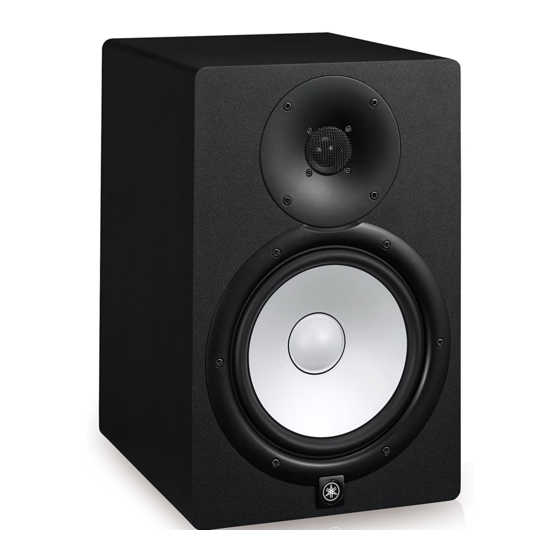
Rear Panel The HS8/HS7/HS5/HS8S switches and connectors are located on the rear panel, as described below. HS8/HS7/HS5 Speaker Input and Response Control 1 LEVEL control Adjusts the output level of the speaker. When set to the 12-o’clock position the speaker is optimized for a nominal input level of +4 dB. -
Page 7: Subwoofer Response Control
AC CUT switch is ON. outlet. 9 AC IN connector Connect the supplied power cable here. First connect the power cord to the subwoofer, then insert the power cord plug into the AC outlet. HS8/HS7/HS5/HS8I/HS7I/HS5I/HS8S Owner’s Manual... -
Page 8: Setup
Plug the power cord into the speaker first, and then insert the AC plug end into an appropriate AC wall outlet. When connecting a mixer (Yamaha MGP or MG series, etc.) to HS series speakers, connect the mixer’s Connecting to an Audio Interface MONITOR OUT or C-R OUT (Control Room) connectors directly to the speakers’... -
Page 9: Connecting To Synthesizer
60˚ Connecting to a Synthesizer or Other Electronic Musical Instrument When connecting an electronic musical instrument such as a Yamaha MOTIF synthesizer to the HS series speakers, connect the instrument’s L/MONO and R outputs to the HS speaker inputs. HS8/HS7/HS5 HS8/HS7/HS5 ... -
Page 10: Adding Subwoofer
Position the tweeters at ear height. the left and right HS8/HS7/HS5 main speakers. High frequencies are quite directional, so for the most accurate monitoring the speakers should be set up so The connections are made as shown below. - Page 11 Turn the level/volume controls on all Screw holes for installing brackets source equipment (audio interface, etc.) all the way down. Set the HS8/HS7/HS5 LEVEL control to the 12-o’clock position, and set both ROOM CONTROL and HIGH TRIM switches to 0 HS8/HS7/HS5/HS8I/HS7I/HS5I/HS8S Owner’s Manual...
-
Page 12: Troubleshooting
• Yamaha does not assume any responsibilities for accidents such as dropping due to insufficient strength at attachment points or Sectional inadequacy of the mounting method. - Page 13 Information for Users on Collection and Disposal of Old Información para los usuarios acerca de la recogida y Equipment desecho de equipos antiguos This symbol on the products, packaging, and/or accompanying Este símbolo en los productos, embalajes y/o documentos documents means that used electrical and electronic products adjuntos indica que los productos eléctricos y electrónicos should not be mixed with general household waste.
-
Page 14: Specifications
* Le contenu de ce mode d’emploi s’applique aux dernières caractéristiques techniques connues à la date de publication du manuel. Pour obtenir la version la plus récente du manuel, accédez au site Web de Yamaha puis téléchargez le fichier du manuel concerné. -
Page 15: Specifications
(80 – 120 Hz, center click) LOW CUT switch (ON/OFF) Indicator Power ON (White LED) Power Consumption 60 W 55 W 45 W 70 W Dimensions HS8/HS8I HS7/HS7I Unit: mm (inch) Unit: mm (inch) 2-M8 2-M8 (HS8I Only) (HS7I only) 334 (13-1/8") 284 (11-3/16") 250 (9-13/16") -
Page 16: Performance Graph
Unit: mm (inch) Unit: mm (inch) 2-M5 (HS5I only) 222 (8-3/4") 170 (6-11/16") 300 (11-13/16") 389 (15-5/16") 2-M5 (HS5I only) Performance Graph HS8/HS8I HS7/HS7I HS5/HS5I HS8S Block Diagram HS8/HS7/HS5 HIGH TRIM STEP FILTER LOWCUT P.AMP HS8I/HS7I/HS5I INPUT 1 LOW CUT ROOM CONTROL... -
Page 17: Tilt Angle (Hs8I/Hs7I/Hs5I Only)
Tilt Angle (HS8I/HS7I/HS5I only) Wall mount Model Bracket Maximum tilt angle BWS251-300 30° BWS251-400 45° HS8I BWS50-260 0° BWS50-190 Not compatible BWS251-300 35° BWS251-400 45° HS7I BWS50-260 0° BWS50-190 Not compatible BWS20-190 0° HS5I BWS20-120 Not compatible Ceiling mount Model Bracket Maximum tilt angle BCS251... - Page 20 Yamaha Pro Audio global website http://www.yamahaproaudio.com/ Yamaha Downloads http://download.yamaha.com/ Manual Development Department © 2016 Yamaha Corporation Published 05/2016 MWZC-B0 Printed in Indonesia ZV05470...