Table of Contents
Advertisement
Quick Links
Areas Covered
Before Reading This Manual
This section explains the notes for your safety and conventions used in this manual.
Chapter 1
Overview
This chapter explains component names and basic operations of this server, as well as an
overview of the software provided with this server. In addition, the workflow, from placing the
server to starting the operation, is also described.
Chapter 2
Checking before OS Installation
This chapter explains the preparation on the server and cautions necessary before OS installation.
Please read this chapter before starting installation.
Chapter 3
OS Installation Using ServerStart
This chapter explains how to install the OS in the server using ServerStart.
Chapter 4
Manual OS Installation
This chapter explains how to install the OS without using ServerStart.
Chapter 5
Operations after OS Installation
This chapter explains the operations to be performed after OS installation. Be sure to perform
those operations before operating the server.
Chapter 6
High Reliability Tools
For stable PRIMERGY server operations, we recommend that high reliability tools be installed.
This chapter explains the installation and necessary settings of high reliability tools.
Chapter 7
Installing Internal Options
This chapter explains how to install internal options.
Chapter 8
Configuring Hardware and Utilities
This chapter explains how to make the environment settings necessary to operate the server and
how to use each utility.
Chapter 9
Operation and Maintenance
This chapter explains the operations that become necessary after starting to use this server as well
as daily care and maintenance.
Appendix
This appendix explains the specifications for the server and for its internal options.
PRIMERGY TX150 S4 User's Guide
1
Advertisement
Table of Contents
Troubleshooting

Related Manuals for Fujitsu primergy TX150


Summary of Contents for Fujitsu primergy TX150
- Page 1 PRIMERGY TX150 S4 User’s Guide Areas Covered Before Reading This Manual This section explains the notes for your safety and conventions used in this manual. Chapter 1 Overview This chapter explains component names and basic operations of this server, as well as an overview of the software provided with this server.
-
Page 2: For Your Safety
It is the customer's responsibility to maintain backup copies in advance. In case of data loss, Fujitsu assumes no liability for data maintenance or restoration and damages that occur as a result of the data loss for any reason, except for items covered under warranty. - Page 3 PRIMERGY TX150 S4 User’s Guide Remarks ■ Warning Descriptions Various symbols are used throughout this manual. These are used to emphasize important points for your safety and that of others. The following are the symbols and their meanings. Fully understand these symbols when reading this manual.
- Page 4 ■ Entering Commands (Keys) Command entries are displayed in the following way. • At each blank in a command line (as pointed out above), press the [Space] key once. • When using Windows or DOS OS, commands are not case sensitive. •...
- Page 5 PRIMERGY TX150 S4 User’s Guide ■ Abbreviations The following expressions and abbreviations are used throughout this manual. table: Abbreviations of Product Names Product name Expressions and abbreviations PRIMERGY TX150 S4 This server or the server ® Windows Microsoft Small Business Server 2003 SBS 2003 ®...
-
Page 6: Reference Information
■ Latest Information about Software Provided with This Server For the latest information regarding ServerStart and other software provided with this server, refer to the Fujitsu PRIMERGY website (http://primergy.fujitsu.com). Warning and Caution Labels Warning and caution labels are found on the server. -
Page 7: Table Of Contents
PRIMERGY TX150 S4 User’s Guide Contents Chapter 1 Overview 1.1 TX150 S4 ..........14 1.2 Supplied Software . - Page 8 3.1.2 Open/create a Configuration File ....... 62 3.1.3 RAID and Disk Wizard ........63 3.1.4 OS Installation Wizard .
- Page 9 PRIMERGY TX150 S4 User’s Guide Chapter 5 Operations after OS Installation 5.1 Memory Dump/Paging File Setting ..... . 142 5.1.1 How to Obtain Memory Dump for Windows Server 2003 and Windows Server 2003 x64 .
- Page 10 Chapter 7 Installing Internal Options 7.1 Before Installing Hardware Options ..... 184 7.2 Removing and Attaching Covers ..... . . 186 7.2.1 Removing Covers .
- Page 11 PRIMERGY TX150 S4 User’s Guide 8.2.12 Server Menu ..........234 8.2.13 Exit Menu .
- Page 12 B.1 Memory ........... 291 B.2 Internal Hard Disk Units .
-
Page 13: Chapter 1 Overview
Chapter 1 Overview This chapter explains component names and basic operations of this server, as well as an overview of the software provided with this server. In addition, the workflow, from placing the server to starting the operation, is also described. -
Page 14: Tx150 S4
Chapter 1 Overview 1.1 TX150 S4 This server is entry server with high-speed processing and cost-effectiveness. This server has the following features. ■ High Reliability ● Memory Modules Enabling High-Speed Processing For the memory, the system is equipped with DDR II 533 Unbuffered Lowprofile enabling high-speed processing. - Page 15 PRIMERGY TX150 S4 User’s Guide ■ High-speed Processing ® ® ® ® ® ® ● Intel Pentium D Processor / Intel Pentium 4 Processor / Intel Celeron D Processor ® ® ® ® ® ® The server has one of the Intel...
-
Page 16: Supplied Software
Chapter 1 Overview 1.2 Supplied Software ServerStart for supporting setup and high reliability tools for avoiding problems during server operation are supplied with this server. 1.2.1 Setup Support Tool - ServerStart ServerStart is a setup support tool that helps to install PRIMERGY. It offers easy server installation and proper installation of recommended drivers. - Page 17 PRIMERGY TX150 S4 User’s Guide ● Supported OS Using ServerStart V5.603, the following OSs can be installed. ® ™ • Microsoft Windows Server 2003, Standard Edition ® ™ • Microsoft Windows Server 2003, Enterprise Edition ® ™ • Microsoft Windows Server 2003, Standard x64 Edition ®...
-
Page 18: Main Window
Chapter 1 Overview ■ Intuitive User Interface The intuitive user interface allows you to easily set the necessary information. ● Main Window When ServerStart is started, the following window appears. The window and tool bar differ depending on the mode. -
Page 19: Tool Bar
PRIMERGY TX150 S4 User’s Guide ● Tool Bar In Guided Mode / Expert Mode Brings you to Brings you to Changes the size Ends ServerStart. the next page. the previous page. of icons. Brings you to Brings you up Resets the status ON/OFF of the tree display is set. -
Page 20: High Reliability Tools
Chapter 1 Overview ■ Network Configuration ServerStart can configure a network at server installation. For details on available network patterns, refer to "Using ServerStart to Configure the Network". ■ Automatic Driver Installation Recommended drivers for automatically recognized expansion cards are installed with the server. This prevents possible mistakes in driver installation, such as installation of an older version or drivers which were not supplied with this server. -
Page 21: Intel Proset
PRIMERGY TX150 S4 User’s Guide ■ System Diagnosis Support Tools The system diagnosis support tool is for supporting system diagnosis during normal operation or in the event of trouble. ● Early Solution to Problems [DSNAP] DSNAP is a command line utility that collects all the failure investigation information. System file configuration information, major registry settings, and event logs can be collected easily from the command line. -
Page 22: Installing High Reliability Tools
Chapter 1 Overview 1.2.3 Installing High Reliability Tools You can install all high reliability tools provided with PRIMERGY by specifying them in "Application Wizard" when the OS is installed with ServerStart. The following high reliability tools are installed. table: High reliability tool installation ServerStart installation High reliability tool Guided mode... -
Page 23: Component Names And Functions
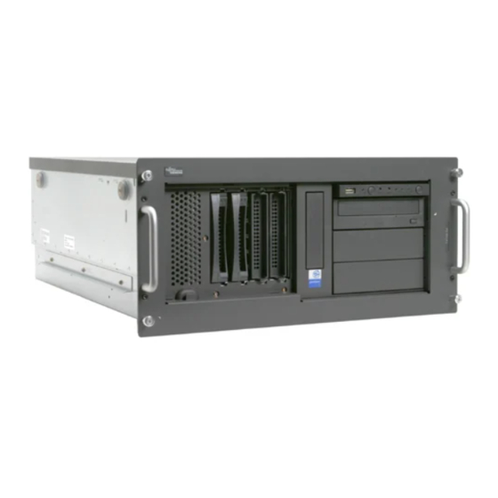
PRIMERGY TX150 S4 User’s Guide 1.3 Component Names and Functions This section explains the component names and functions of the server and baseboard. 1.3.1 Server (Front View) a b c d e Drive cover Pull the drive cover down to the lower end of the server. -
Page 24: Power Switch
Chapter 1 Overview e Maintenance switch This switch is used only by maintenance personnel. Do not touch this. f System status LED ( This LED lights or blinks in amber when an error is detected in the server components. If this LED lights or blinks, contact an office listed in the "Contact Information"... - Page 25 PRIMERGY TX150 S4 User’s Guide ■ Inside the Hard Disk Cover Hard disk cover Remove the hard disk cover. a 3.5-inch storage bay Contains an internal hard disk. b Hard disk access display LED ( This LED is lit green when data is being written to or read from the hard disk.
-
Page 26: Server (Rear View)
Chapter 1 Overview 1.3.2 Server (Rear View) a Inlet Connects power cables. b Mouse connector ( A mouse is plugged in. c System status LED This LED lights or blinks in amber when an error is detected in the server components. If this LED lights or blinks, contact an office listed in the "Contact Information"... -
Page 27: Parallel Port
PRIMERGY TX150 S4 User’s Guide g Parallel port ( A printer cable is plugged in. h USB connector ( Connects peripheral equipment conforming to the USB standard (2.0 or 1.1). i LAN (10/100/1000BASE-T) port ( An Unshielded Twisted Pair (UTP) cable is plugged in. -
Page 28: Server (Internal)
Chapter 1 Overview 1.3.3 Server (Internal) Rear Front a Power supply unit b Memory slot Contains memory. c 5-inch storage bay Contains a 5-inch internal optional device. Unlike external devices, an internal option does not need to be connected to the outlet because its power is supplied from the server. -
Page 29: Baseboard
PRIMERGY TX150 S4 User’s Guide 1.3.4 Baseboard a CPU socket Installs the CPU. b Memory slot Contains memory. If more memory is added, the amount of the data that can be read at a time increases and the processing performance of the server improves. -
Page 30: Pci Slots
Chapter 1 Overview j PCI Slots Contains an expansion card. PCI slots (1 to 5) are numbered from bottom to top in the above figure. k Internal Power connector An RSB power cable is plugged in when a remote service board is installed. l Server Control connector A server control cable is plugged in when a remote service board is installed. -
Page 31: Standard Operations
PRIMERGY TX150 S4 User’s Guide 1.4 Standard Operations This section explains such standard operations as turning the server on/off and inserting/ejecting CD-ROMs. 1.4.1 Sliding the Drive Cover Turn the drive cover key counterclockwise to unlock the cover. Drive cover key Slide the drive cover. -
Page 32: Opening The Rack Door
Chapter 1 Overview The driver cover key is unique to each device. Do not lose the key. If the key is lost, the lock must be broken and replaced on a paid basis. Manage the drive cover key very carefully. Contact an office listed in the "Contact Information"... - Page 33 PRIMERGY TX150 S4 User’s Guide Turn the handle in the direction of the arrow and pull it forward. Turn and then pull ■ Opening the Rear Door Turn the rack key and pull the rack handle up.
-
Page 34: Turning On The Server
When operating the device outside of this operating environment, the server may operate improperly, damage data etc. Furthermore, Fujitsu cannot be held responsible for any related damage, malfunction, or loss of data, etc. • The fans rotate at high speed immediately after the server is turned on, but this is not defective. -
Page 35: Turning Off The Server
PRIMERGY TX150 S4 User’s Guide Make sure that the floppy disk drive and CD-ROM drives are empty. Press the power switch of the monitor and peripheral devices. Press the power switch on the front of the server. The server's power LED turns green. - Page 36 Chapter 1 Overview Shut down the OS. In the following cases, the server is turned off after the OS is shut down (Step 4 is not necessary). • Windows OS • ServerView is installed In other cases, make sure that the access LEDs of floppy disk and hard disk are off when the OS is shut down.
-
Page 37: Inserting And Ejecting A Floppy Disk
PRIMERGY TX150 S4 User’s Guide 1.4.5 Inserting and Ejecting a Floppy Disk ■ Cautions When using floppy disks, note the following points to avoid failures: • Do not expose the disk to any fluids. • Do not open the shutter of the floppy disk and touch the disk surface. - Page 38 Chapter 1 Overview ■ Inserting the Floppy Disk Use a floppy disk formatted in DOS/Windows. Operations are not guaranteed when you use other floppy disks. Insert the floppy facing the label up into the floppy disk drive at the side with a shutter.
- Page 39 PRIMERGY TX150 S4 User’s Guide Press the floppy disk eject button. The floppy disk comes out.
-
Page 40: Inserting And Ejecting A Cd-Rom (Dvd-Ram)
Chapter 1 Overview 1.4.6 Inserting and Ejecting a CD-ROM (DVD-RAM) This section explains how to insert and eject a CD-ROM and DVD-RAM. Unless otherwise noted, CD- ROM includes DVD-RAM. When using CD-ROMs, note the following points to avoid failures. For information about DVD-RAM drive, refer to the manual which comes with the DVD-RAM unit. ■... - Page 41 PRIMERGY TX150 S4 User’s Guide ■ Inserting the CD-ROM Make sure the server is turned on and press the CD-ROM eject button. The CD-ROM tray comes out a little. CD-ROM eject button Place the CD-ROM (label side up) onto the tray.
-
Page 42: Workflow
Chapter 1 Overview 1.5 Workflow To start the server operation, perform the following procedures. Installing the server Refer to "Safety Precautions" and "Start Guide" to install the server to a suitable place. Preparing the server - Install hardware options - Set hardware Refer to "2.1 Preparation on the server", "Chapter 7 Installing Internal Options"... - Page 43 Chapter 2 Checking before OS Installation This chapter explains the preparation on the server and cautions necessary before OS installation. Please read this chapter before starting installation. 2.1 Preparation on the Server ......2.2 Selecting the Installation Method .
-
Page 44: Chapter 2 Checking Before Os Installation
Chapter 2 Checking before OS Installation 2.1 Preparation on the Server Before starting installation, install internal options to the server and perform necessary hardware settings. 2.1.1 Installing Internal Options Internal options are classified into those that must be installed before the OS installation and those that must be installed after the OS installation. -
Page 45: Hardware Settings
PRIMERGY TX150 S4 User’s Guide ■ Cautions for Installing a Memory Module This server supports up to 8GB of memory. However, the maximum installable size varies depending on the OS. Furthermore, since the server uses part of the memory as PCI resources, the maximum available size is limited. -
Page 46: Scsi Setup Utility
Chapter 2 Checking before OS Installation Take the following steps in the BIOS Setup Utility. 1. Start the BIOS Setup Utility. "8.2.1 Starting and Exiting the BIOS Setup Utility" (pg.217) 2. Select the [Peripheral Configuration] submenu from the [Advanced] menu and press the [Enter] key. -
Page 47: Selecting The Installation Method
To set up multiple servers with the same model and configuration, refer to "3.5 Installation on Multiple (the Second and Subsequent) Servers" ( pg.108). Linux For the use of Linux, refer to the Fujitsu PRIMERGY What OS will you use? website (http://primergy.fujitsu.com). -
Page 48: Precautions On Installation
Chapter 2 Checking before OS Installation 2.3 Precautions on Installation Read the following notes before starting OS installation. 2.3.1 Installation Partition Size For installation using ServerStart, the installation partition size can be set as follows, depending on the OS to be installed and format. table: Installation Partition Size Windows Server 2003 Available size... -
Page 49: Notes On Configuring Raid
PRIMERGY TX150 S4 User’s Guide 2.3.2 Notes on Configuring RAID RAID can be configured with hard disk units connected to the SCSI controller on the baseboard. Configurable RAID level differs depending on whether the onboard SCSI controller or the SCSI array controller card is used to configure the array system. -
Page 50: Notes On A Multiple Lan Adapter Configuration
Chapter 2 Checking before OS Installation ■ Notes • When a RAID-configured disk is used Hard disk units that have been used before may have unwanted partition information or array configuration information, which may cause unexpected problems. If you connect any hard disk units with usage history to this server, format them at low level on another system before connecting them to the server. - Page 51 PRIMERGY TX150 S4 User’s Guide ■ Ejecting the CD-ROM Do not eject the ServerStart CD-ROM while ServerStart is running. If the ServerStart CD-ROM is ejected and inserted again, ServerStart starts up in multiple windows, and settings you have made can be lost.
-
Page 52: Expansion Cards Supported By Serverstart
Chapter 2 Checking before OS Installation 2.3.5 Expansion Cards Supported by ServerStart ServerStart supports automatic driver installation for the following expansion cards. table: Automatic Expansion Card Driver Installation Name Model Onboard FDD/IDE SCSI array controller card PG-140D1 Onboard LAN PCI-E Onboard VGA LAN Card PG-1852... -
Page 53: Preparation For Using Serverstart On A Client Computer
PRIMERGY TX150 S4 User’s Guide 2.4 Preparation for Using ServerStart on a Client Computer When using the preconfiguration mode for setting installation information in advance or when creating a driver disk using the FloppyBuilder function, install ServerStart on the client computer. - Page 54 Chapter 2 Checking before OS Installation Click [OK]. The Windows installer starts and the setup window appears. Click [Next]. The [License Agreement] window appears. Select [I accept the license agreement] and click [Next]. The [User Information] window appears. Enter the user information of the software and click [Next]. The [Destination Folder] window appears.
- Page 55 PRIMERGY TX150 S4 User’s Guide Disable [ServerStart - remote installation] and click [Next]. The [Ready to Install the Application] window appears. Specify whether or not to copy the contents of the CD. When you select [Yes] for "enable the use of ServerStart without CD.", you can start the preconfiguration mode on the client computer without using the CD-ROM.
-
Page 56: Uninstalling Serverstart
Select [Fujitsu ServerStart] and click [Remove] (or [Modify]). When the uninstallation is executed successfully, Fujitsu ServerStart is deleted. If [ServerStart - remote installation] has been installed using ServerStart, "FjPXEServer" seems undeleted. Leave it and complete the operation. - Page 57 Chapter 3 OS Installation Using ServerStart This chapter explains how to install the OS in the server using ServerStart. 3.1 Guided Mode ....... . . 3.2 Preconfiguration Mode .
-
Page 58: Chapter 3 Os Installation Using Serverstart
Chapter 3 OS Installation Using ServerStart 3.1 Guided Mode In guided mode, follow the wizard to specify hardware configuration and the OS to be installed, save the information necessary for installation in a configuration file, and install the OS. 3.1.1 Starting Up the Guided Mode Start up the guided mode. - Page 59 PRIMERGY TX150 S4 User’s Guide The network setting window for remote installation appears. Click [OK]. The [Initialization of ServerStart core running] window appears and the ServerStart initialization process starts. Depending on the hardware configuration, this process may take a few minutes.
- Page 60 Chapter 3 OS Installation Using ServerStart When the process is completed, the [Create a ServerStart Floppy Disk] window appears. Click [Build a ServerStart Floppy Disk]. " Creation of a ServerStart floppy disk starts. When the creation is completed, the Floppy disk has "...
- Page 61 PRIMERGY TX150 S4 User’s Guide Click [Prepare & initiate an unattended installation of (OS)]. The guided mode for the selected OS starts up. Start up the wizards to set items in the following procedures. Exiting the wizard returns the display to the guided mode window.
-
Page 62: Open/Create A Configuration File
Chapter 3 OS Installation Using ServerStart 3.1.2 Open/create a Configuration File Open a configuration file. Or create a new one. Click [Start here to create a complete configuration file]. The [Open ServerStart Configuration File] window appears. Once a configuration file is opened, another file cannot be opened until you click [Close and save Configuration File]. -
Page 63: Raid And Disk Wizard
PRIMERGY TX150 S4 User’s Guide 3.1.3 RAID and Disk Wizard Configure RAID, and create and format hard disk partitions. Click [RAID and Disk Wizard: RAID configuration and hard disk pertitioning / formatting]. The [Configuration for Disks and RAID Controllers] window appears. - Page 64 Chapter 3 OS Installation Using ServerStart ■ Installation While Maintaining the Established RAID Environment Select [Logical Drive View] on the [Configuration for Disks and RAID Controllers] window. Add a partition 1. Click [Add Partition]. A partition is added. Add required partitions. 2.
-
Page 65: Configuring Raid
PRIMERGY TX150 S4 User’s Guide ■ Configuring RAID Select [Mass Storage Controller View] on the [Configuration for Disks and RAID Controllers] window. Click [Details]. As the default values are configured, confirm the settings and modify them as necessary. Add partitions as necessary. - Page 66 Chapter 3 OS Installation Using ServerStart 2. Click [Details] and modify the settings as necessary. The partition configuration is displayed. As the default values are configured, confirm the settings and modify them as necessary.
-
Page 67: Os Installation Wizard
PRIMERGY TX150 S4 User’s Guide 3.1.4 OS Installation Wizard Set computer information, user information, and the network protocol. ServerStart can configure multiple network patterns. When configuring a domain controller, refer to "Using ServerStart to Configure the Network". The setup window differs depending on the OS to be installed. The following describes operations on Windows Server 2003 R2. - Page 68 Chapter 3 OS Installation Using ServerStart Set items and click [Next]. When using the CD-ROM applied Service Pack 1 on Windows Server 2003, select the [(OS) including SP1] menu from the [Operating System Type] list. The [Installation Directory and Time Zone] window appears. Set items and click [Next].
- Page 69 PRIMERGY TX150 S4 User’s Guide Set items and click [Next]. The [Network Protocol] window appears.
- Page 70 Chapter 3 OS Installation Using ServerStart Set items and click [Next]. The [Software Components] window appears.
- Page 71 PRIMERGY TX150 S4 User’s Guide If Windows Server 2003 R2 is selected at the Computer Identification, R2 components are always copied to the hard disk. To install the components, click [Properties] and check the components to be installed. Set items and click [Next].
-
Page 72: Application Wizard
[>>]. Set all applications to be installed on the [Selected applications] list. Fujitsu ServerView, Broadcom Advanced Control Suite (BACS), and RAID Management Tool are always installed in guided mode. In expert mode, the selection can be released. Click [leave wizard]. -
Page 73: Close/Save The Configuration File
PRIMERGY TX150 S4 User’s Guide 3.1.6 Close/save the Configuration File When settings in all wizards are completed, save the configuration file. Click [Close and save Configuration File]. The [Save ServerStart Configuration File] window appears. Click [Save As]. The configuration file is saved. - Page 74 Chapter 3 OS Installation Using ServerStart 1. When RAID has been configured, the system restarts. 2. If a message prompts you to insert the SCSI Array Controller Document & Tool CD V6.0L10, insert the CD-ROM and click [OK]. 3. If a message prompts you to insert the PRIMERGY Document & Tool CD, insert the CD and click [OK].
-
Page 75: Preconfiguration Mode
If the contents of the ServerStart CD-ROM have been copied to the computer 1. Click [Start] → [Programs] → [Fujitsu ServerStart] → [ServerStart]. ServerStart starts up and the [Welcome to ServerStart] window appears. If the contents of the ServerStart CD-ROM have not been copied to the computer 1. - Page 76 Chapter 3 OS Installation Using ServerStart Click [FloppyBuilder]. The [ServerStart FloppyBuilder] window appears. Click [ServerStart Status Diskette]. A message prompts you to insert the floppy disk. Insert the ServerStart floppy disk supplied with the server and click [OK]. Set the ServerStart floppy disk in the write-enabled state. Creation of a ServerStart floppy disk starts.
- Page 77 PRIMERGY TX150 S4 User’s Guide Select the OS to be installed. The [Preparing the Installation] window appears.
-
Page 78: Configure Settings In Wizards
Chapter 3 OS Installation Using ServerStart 3.2.2 Configure Settings in Wizards Click the wizards to set items in the following procedures. For setting procedures, refer to description on guided mode wizards ("3.1.2 Open/create a Configuration File" ( pg.62) to "3.1.5 Application Wizard" ( pg.72)). -
Page 79: Close/Save The Configuration File
PRIMERGY TX150 S4 User’s Guide 3.2.3 Close/save the Configuration File When settings in all wizards are completed, save the configuration file. Click [Close and save Configuration File]. The [Save ServerStart Configuration File] window appears. Click [Save As]. The [ServerStart Session IP Settings] window appears. -
Page 80: Starting Os Installation
Chapter 3 OS Installation Using ServerStart 3.2.4 Starting OS Installation Install the OS to the server using the created configuration file. During installation, do not use the mouse or keyboard unless it is necessary for installation operations. Otherwise, installation may fail. Turn on the server and insert the ServerStart Disc 1 CD-ROM immediately. - Page 81 PRIMERGY TX150 S4 User’s Guide 4. If a message prompts you to insert the Service Pack CD-ROM, insert the CD-ROM and click [OK]. This message does not appear when Service Pack is not selected. 5. If a message prompts you to insert the ServerStart CD-ROM, insert the ServerStart Disc 2 CD-ROM and click [OK].
-
Page 82: Expert Mode
Chapter 3 OS Installation Using ServerStart 3.3 Expert Mode In expert mode, start up Disk Manager, format the installation partition, and install the Use the expert mode only when you want to perform installation while maintaining the existing partitions. Use the guided mode for normal installation. 3.3.1 Starting Up the Expert Mode Start up the expert mode. - Page 83 PRIMERGY TX150 S4 User’s Guide Select the OS to install. Click [Install MS Windows Server 2003 interactively (expertise required)]. The expert mode starts. Start up the configuration tools to set items in the following procedures. Exiting a tool returns to the display to the expert mode window.
-
Page 84: Disk Manager
Chapter 3 OS Installation Using ServerStart 3.3.2 Disk Manager Start up Disk Manager and format the installation partition. Click [Use Disk Manager to partition and format your disk drives]. Disk Manager starts up. Format the OS installation partition. Select the OS installation partition and click the [Partition] menu →... -
Page 85: Os Installation Wizard
PRIMERGY TX150 S4 User’s Guide 3.3.3 OS Installation Wizard Set computer information, user information, and the network protocol. ServerStart can configure multiple network patterns. When configuring a domain controller, refer to "Using ServerStart to Configure the Network". The setting window differs depending on the OS to be installed. The following describes operations on Windows Server 2003 R2. -
Page 86: Application Wizard
Chapter 3 OS Installation Using ServerStart Set items and click [Next]. The [Software Components] window appears. If Windows Server 2003 R2 is selected at the Computer Identification, R2 components are always copied to the hard disk. To install the components, click [Properties] and check the components to be installed. - Page 87 PRIMERGY TX150 S4 User’s Guide Click [Yes]. The following window appears. Enter the file name and click [Save As]. Installation starts automatically. 1. If a message prompts you to insert the SCSI Array Controller Document & Tool CD V6.0L10, insert the CD-ROM and click [OK].
- Page 88 Chapter 3 OS Installation Using ServerStart When a message prompts you to insert the OS CD-ROM, insert the CD-ROM and click [OK]. For Windows 2000 / Windows Server 2003 / Windows Server 2003 x64 Insert the OS CD-ROM (Installation CD-ROM). For Windows Server 2003 R2 / Windows Server 2003 R2 x64 Insert the OS CD-ROM (Installation CD-ROM) Disc 1.
-
Page 89: Remote Installation
PRIMERGY TX150 S4 User’s Guide 3.4 Remote Installation ServerStart supports remote installation. Before performing remote installation, be sure to read "Cautions for Remote Installation" in the online help. 3.4.1 Overview of Remote Installation Remote installation is a method to save resources necessary for installation, such as the OS and Service Pack, in a different server on the network and install them via the network. -
Page 90: Installation Method
Chapter 3 OS Installation Using ServerStart ■ Installation Method Remote installation uses a PXE or a remote resource server. ● Remote Installation Using a PXE Server In remote installation using a PXE server, the network startup (PXE) function of the PXE server starts up the target server and performs installation in preconfiguration mode. -
Page 91: System Requirements For Remote Resource/Pxe Servers
PRIMERGY TX150 S4 User’s Guide 3.4.2 System Requirements for Remote Resource/PXE Servers Because remote installation is performed via a network, the environment must have at least one Windows server and a local area network. In addition, the following environment is required. -
Page 92: Preparation Of The Pxe Server (When The Pxe Server Is Used)
Chapter 3 OS Installation Using ServerStart ● Checking Server Free Space The following table shows the amount of free space required for each installation resource. table: Free Space Required for Resources Resource Required free space ServerStart Disc 1 approx. 650MB ServerStart Disc 2 approx. - Page 93 PRIMERGY TX150 S4 User’s Guide Starting the DHCP Service Installing ServerStart Checking Services Setting TFTP Preparation of Resources ■ Starting the DHCP Service Check that the DHCP service is running on the same network. If the DHCP service function is not installed, perform the following procedures to install the DHCP service.
- Page 94 Chapter 3 OS Installation Using ServerStart ■ Installing ServerStart Insert the ServerStart Disc 1 CD-ROM into the PXE server. The [ServerStart Launcher] window appears. When the [ServerStart Launcher] window does not appear, execute "Launcher.exe" in the CD- ROM. Click [OK]. The Windows installer starts and the Setup window appears.
- Page 95 PRIMERGY TX150 S4 User’s Guide Select the installation folder and click [Next]. To change the installation folder, click [Browse] and select the folder. The [Select Features] window appears. Configure [ServerStart - remote installation] so that it will be installed. To install Windows Server 2003 x64, configure [Microsoft Windows Server x64 Edition -Remote install] as well.
- Page 96 Chapter 3 OS Installation Using ServerStart Click [Next]. The [contents tree] window appears. Configure the ServerStart image necessary for network startup (PXE) and click [Next]. The [Useraccount for access to the content tree] window appears.
- Page 97 PRIMERGY TX150 S4 User’s Guide Specify the user account for the content tree and click [Next]. The [PXE server] window appears. Select [yes] when the PXE server performs the DHCP service or select [no] when the DHCP and PXE servers are configured separately. Then click [Next].
- Page 98 Chapter 3 OS Installation Using ServerStart Click [show Readme file]. The [Readme] window appears. Read the text. When you finish, click [ ] in the upper-right corner of the window to close the [Readme] window. Click [Next]. The image file is copied. The image file copying process takes about 10 to 20 minutes.
- Page 99 Guest account to obtain the image via network startup (PXE). Click [Start] → [Programs] → [Accessories] → [Windows Explorer] and move to the TFTP path (the default is C:\Program Files\Fujitsu Siemens\DeploymentService\tftp). Right-click the TFTP folder and click [Properties].
-
Page 100: Preparation Of Remote Resources
Chapter 3 OS Installation Using ServerStart Click the [Security] tab, add the Guest account, and set the "Read and execute", "View folder contents list", and "Read" access permissions. The preparation of the PXE server has been completed. Then, perform "3.4.4 Preparation of Remote Resources" ( pg.100). 3.4.4 Preparation of Remote Resources Store resources to be installed on the remote resource server (PXE server) before starting installation. -
Page 101: Starting Remote Installation Using A Pxe Server
PRIMERGY TX150 S4 User’s Guide 3.4.5 Starting Remote Installation Using a PXE Server Perform remote installation using a PXE server in the following procedures. Checking the Network Startup (PXE) Setting Checking the MAC Address Creating a Configuration File (Setting of remote installation) Starting remote Installation ■... - Page 102 On the PXE server, start up ServerStart. If ServerStart has already been started, you do not have to restart it. If it is not started, click [Start] → [Programs] → [Fujitsu ServerStart] → [ServerStart]. The [Welcome to ServerStart] window appears.
- Page 103 PRIMERGY TX150 S4 User’s Guide Configure remote installation. 1. Enter the "MAC address of target system". 2. Select the "PRIMERGY model type". 3. Specify the "Configuration File" containing the installation settings. Click [Start Installation]. Installation starts. All disk contents on the target server are deleted.
-
Page 104: Starting Remote Installation Using A Remote Resource Server
Chapter 3 OS Installation Using ServerStart Turn on the target server. It is started up via the network (PXE) and installation starts. When the resources have been copied, the "Preparation for automatic OS installation has completed." message appears. Subsequent installation is performed automatically. When the installation is completed, an installation completion message appears on the target server. - Page 105 PRIMERGY TX150 S4 User’s Guide ■ Checking Remote Resources Check that the remote resource server is shared properly. Start up "Command Prompt" on the remote resource server. Enter the following and press the [Enter] key. prompt:>net share Check that the created shared folder is displayed properly.
- Page 106 Chapter 3 OS Installation Using ServerStart Click [MS Windows Operating Systems]. The [Install Microsoft Windows Operating System Installation] window appears. Select the OS to install and the mode. Set items in wizards and save the configuration file. For settings in wizards, refer to "3.1 Guided Mode" ( pg.58) or "3.3 Expert Mode" ( pg.82). Set items in wizards and save the configuration file.
- Page 107 PRIMERGY TX150 S4 User’s Guide Click [Start]. Installation starts. At steps where the CD-ROM for resources such as the OS to be installed is necessary, the resource is automatically acquired from the resource server via the network. Eject the CD-ROM and floppy disk and click [OK].
-
Page 108: Installation On Multiple (The Second And Subsequent) Servers
Chapter 3 OS Installation Using ServerStart 3.5 Installation on Multiple (the Second and Subsequent) Servers This chapter explains how to perform installation on multiple servers using ServerStart. By editing the configuration file created for installation on the first server, you can use it for installation on other servers of the same model and configuration. -
Page 109: Installation In Guided Mode
PRIMERGY TX150 S4 User’s Guide 3.5.2 Installation in Guided Mode Edit the configuration file and perform installation in guided mode. Turn on the server and insert the ServerStart Disc 1 CD-ROM immediately after that. ServerStart starts up and a message prompts you to insert the ServerStart floppy disk. -
Page 110: Installation In Preconfiguration Mode
When the CD has been copied on Windows 2000 Professional/Windows XP Professional 1. Click [Start] → [Programs] → [Fujitsu ServerStart] → [ServerStart]. ServerStart starts up and the [Welcome to ServerStart] window appears. When Windows NT is used or CD has not been copied 1. - Page 111 PRIMERGY TX150 S4 User’s Guide Insert the ServerStart floppy disk copied in the preparatory procedure into the floppy disk drive and click [Start here to configuration file]. The [Open ServerStart Configuration File] window appears. Specify "SerStartBatch.ini" on drive A and click [Create].
- Page 112 Chapter 3 OS Installation Using ServerStart...
-
Page 113: Chapter 4 Manual Os Installation
Chapter 4 Manual OS Installation This chapter explains how to install the OS without using ServerStart. 4.1 Creating Driver Disks ......114 4.2 Starting Manual Installation . -
Page 114: Creating Driver Disks
Chapter 4 Manual OS Installation 4.1 Creating Driver Disks When installing the OS manually, it is necessary to create driver installation disks beforehand. Also, driver disks must be created when you add an expansion card during server operation. 4.1.1 Required Driver Disks Prepare for the floppy disks in advance to create the driver disks. -
Page 115: For Windows 2000 Server
Driver provided with the Server Start CD-ROM Graphic controller Standard driver provided with the OS Onboard SCSI controller PRIMERGY TX150 S4 Onboard SCSI Driver Windows 2003 Drivers Disk V1.0L20 RAID Ctrl 0-Channel 128MB w/ BBU PG-140D1(LSI Logic MegaRAID320-0X Step2) Driver (PG-140D1) Windows 2000/2003 Drivers Disk V3.0L20... -
Page 116: How To Create Driver Disks [Floppybuilder Function]
If ServerStart has already been started, you do not have to restart it. If it is not started, perform the following startup procedures. ● For Creation on a Client Computer When the CD has been copied Click [Start] → [Programs] → [Fujitsu ServerStart] → [ServerStart]. ServerStart starts up and the [Welcome to ServerStart] window appears. - Page 117 PRIMERGY TX150 S4 User’s Guide When the CD has not been copied Insert the ServerStart Disc 1 CD-ROM into the client computer. ServerStart starts up and the [Welcome to ServerStart] window appears. ● For Creation on the Server Turn on the server and insert the ServerStart Disc 1 CD-ROM immediately.
- Page 118 Chapter 4 Manual OS Installation Click [or Insert a ServerStart Floppy Disk to Start ServerStart]. The [Welcome to ServerStart] window appears. Eject the ServerStart floppy disk.
- Page 119 PRIMERGY TX150 S4 User’s Guide ■ Creating Driver Disks Start up ServerStart and confirm that the [Welcome to ServerStart] window is displayed. Click [FloppyBuilder]. The [ServerStart FloppyBuilder] window appears. Select the Drivers Diskettes for Windows Server 2003 / Windows 2000 Server or Windows Server 2003 x64.
-
Page 120: Starting Manual Installation
Chapter 4 Manual OS Installation 4.2 Starting Manual Installation This section explains the procedures for installing the OS manually. 4.2.1 Installing Windows Server 2003 x64 For details on the OS settings, refer to the following URL. http://www.microsoft.com/technet/prodtechnol/exchange/2003/Library/default.mspx Create driver disks. Prepare necessary drivers before installing Windows Server 2003 x64. - Page 121 PRIMERGY TX150 S4 User’s Guide The [Windows Server 2003 x64 Setup] window appears. Immediately, the following message appears at the bottom of the window. Press the [F6] key. Press F6 if you need to install a third party SCSI or RAID driver ...
- Page 122 Chapter 4 Manual OS Installation Install the LAN driver. Install the LAN driver using the driver disk created from the ServerStart CD-ROM. For more details, refer to "4.3 Installing the LAN Driver" ( pg.133). Install the LAN driver advanced set up tool. For information about onboard LAN driver advanced setup tool, refer to "5.6.1 BACS Installation"...
-
Page 123: Installing Windows Server 2003 / Sbs 2003
PRIMERGY TX150 S4 User’s Guide ● Before Starting Operation After OS installation, refer to "Chapter 5 Operations after OS Installation" ( pg.141) and perform the necessary procedures. ■ For Onboard SCSI Configuration When the array is not configured, and OS is installed in the hard disk drive connected with an onboard SCSI controller, modify the registry for the onboard SCSI controller before starting operation. - Page 124 Chapter 4 Manual OS Installation Turned on the server and configure RAID. If RAID is not required to be configured, proceed to step 3. Turn off the server after configuring the array system. To configure the array system with onboard SCSI array controller Turn on the server to display the following message and press the [Ctrl] + [C] key to start up the SCSI Setup Utility.
- Page 125 PRIMERGY TX150 S4 User’s Guide 2. When the "Please insert the disk labeled Manufacturer-supplied hardware support disk into Drive A:" message appears, insert the driver disk created and press the [Enter] key. The following message appears. You have chosen to configure a SCSI Adapter for use with Windows, using a device support disk provided by an adapter manufacturer.
- Page 126 Chapter 4 Manual OS Installation For SBS 2003 The server is restarted after installing the operating system. 1. After restarting the server, log on to the server with the Administrator account. The installation of server tools and the application is started, and the following window appears.
-
Page 127: Installing Windows 2000 Server
PRIMERGY TX150 S4 User’s Guide 12. Click [Close] to close the properties window. Install the ChipSet driver. 1. Insert the ServerStart Disc 1 CD-ROM into the drive of the server. When the ServerStart window appears, exit ServerStart. 2. Execute the following command on the CD-ROM. - Page 128 Chapter 4 Manual OS Installation Turned on the server and configure RAID. If RAID is not required to be configured, proceed to step 3. Turn off the server after configuring the array system. To configure the array system with onboard SCSI array controller Turn on the server to display the following message and press the [Ctrl] + [C] key to start up the SCSI Setup Utility.
- Page 129 PRIMERGY TX150 S4 User’s Guide 2. When the "Please insert the disk labeled Manufacturer-supplied hardware support disk into Drive A:" message appears, insert the driver disk created and press the [Enter] key. The following message appears. You have chosen to configure a SCSI Adapter for use with Windows 2000, using a device support disk provided by an adapter manufacturer.
- Page 130 Chapter 4 Manual OS Installation 2. Right-click the [My Computer] icon on the desktop and click [Manage] from the displayed menu. 3. Click [Device Manager] from the displayed list. 4. Double-click [HP SDR GEM SCSI Processor Device] under [System devices]. The properties window appears.
- Page 131 PRIMERGY TX150 S4 User’s Guide 12. Eject the ServerStart CD-ROM from the CD-ROM drive and restart the system to make the settings effective. Apply Windows 2000 Service Pack. For details, refer to the description in the window. Install the USB 2.0 driver.
-
Page 132: Installing Linux
The installation of Windows 2000 Server has completed. ● Before Starting Operation After OS installation, refer to "Chapter 5 Operations after OS Installation" ( pg.141) and perform the necessary procedures. 4.2.4 Installing Linux For the use of Linux, refer to the Fujitsu PRIMERGY website (http://primergy.fujitsu.com). -
Page 133: Installing The Lan Driver
PRIMERGY TX150 S4 User’s Guide 4.3 Installing the LAN Driver This section explains the procedure for installing the driver. In addition to the case where the OS is installed manually, the driver must be installed when a LAN card is added. -
Page 134: Installing The Lan Driver (Windows Server 2003 / Sbs 2003)
Chapter 4 Manual OS Installation Select [Install the software automatically (Recommended)] and click [Next]. The driver will be installed. Click [Finish]. Click [Close] to close the properties window. ■ Installing the LAN Driver Perform the following procedures on each [Ethernet controller] under [Other devices] in [Device Manager]. - Page 135 PRIMERGY TX150 S4 User’s Guide For the following LAN card, the network adapter is recognized when the card is mounted during OS installation. • PG-1852 Click [Start] → [Administrative Tools] → [Computer Management]. Click [Device Manager]. On the Device Manager list, check if a recognized network adapter is present.
-
Page 136: Updating Lan Drivers
Chapter 4 Manual OS Installation When the LAN driver is installed to [Other devices] before updating the driver for the network adapter recognized immediately after the OS installation When driver installation starts, the following window appears. Clicking [Finish] displays the [Help and Support Center] window. Click [X] to close the window. After installation, the "!"... - Page 137 PRIMERGY TX150 S4 User’s Guide ■ Installing the LAN Driver Perform the following procedures on each [Ethernet controller] under [Other devices] in [Device Manager]. Insert the driver disk created from the ServerStart CD-ROM into the server. For the onboard LAN, insert the ServerStart CD-ROM.
-
Page 138: Installing The Lan Driver (Windows 2000 Server)
Chapter 4 Manual OS Installation 4.3.3 Installing the LAN Driver (Windows 2000 Server) Insert the driver disk created from the ServerStart CD-ROM into the server. Right-click the [My Computer] icon on the desktop and select [Manage] from the displayed menu. Click [Device Manager]. -
Page 139: Latest Drivers
Onboard LAN (1000BASE-T) Broadcom NetXtreme Gigabit Ethernet PG-1852 Intel(R) PRO/1000 MT Desktop Adapter PG-1892 Intel(R) PRO/1000 MT Server Adapter PG-2861 Intel(R) PRO1000 PT Dual Port Server Adapter 4.3.4 Latest Drivers For the latest drivers, refer to the Fujitsu PRIMERGY website (http://primergy.fujitsu.com). - Page 140 Chapter 4 Manual OS Installation...
- Page 141 Chapter 5 Operations after OS Installation This chapter explains the operations to be performed after OS installation. Be sure to perform these operations before operating the server. 5.1 Memory Dump/Paging File Setting ....142 5.2 Creating a Disk for System Recovery .
-
Page 142: Chapter 5 Operations After Os Installation
Chapter 5 Operations after OS Installation 5.1 Memory Dump/Paging File Setting Before starting operating this server, configure the setting for obtaining memory dump. The setting procedure varies between Windows Server 2003 and Windows 2000 Server. ● Memory Dump If memory dump is set, debugging information will be automatically saved when a STOP error (fatal system error) occurs in the system. - Page 143 PRIMERGY TX150 S4 User’s Guide ● Kernel Memory Dump Information of only kernel memory space is recorded. The file is stored in the directory displayed in the [Dump file] box. Capacity required for kernel memory dump is as follows: • Paging file: Depending on installed physical memory amount For memory of 256 to 1,373MB - Installed physical memory x 1.5...
- Page 144 Chapter 5 Operations after OS Installation Click the [Advanced] tab and click [Settings] in [Startup and Recovery]. The [Startup and Recovery] window appears. Set as follows: 1. In the [Write debugging information] section, select the memory dump file type. • Complete memory dump (Recommended) The whole system memory information is recorded to the memory dump file.
- Page 145 PRIMERGY TX150 S4 User’s Guide ■ Paging File Setting Set up the paging file according to the following procedures: Log on to the server with administrator privileges. Check free space of the drive where the system is installed. ■ Check the required amount of free space according to "...
- Page 146 Chapter 5 Operations after OS Installation Click [Change] in the [Virtual memory] section. The [Virtual Memory] window appears. Specify the drive where the paging file is to be created. In [Drive], select the drive where the system is installed. The selected drive is displayed in [Drive] in [Paging file size for selected drive]. Select [Custom size] and enter a value in [Initial size].
-
Page 147: How To Obtain Memory Dump For Windows 2000 Server
PRIMERGY TX150 S4 User’s Guide Restart the system. The setting is enabled after the system is restarted. 5.1.2 How to Obtain Memory Dump for Windows 2000 Server Check the following settings before starting configuration to obtain memory dump. ■ Checking Hard Disk Free Space Once memory dump is obtained, a file containing contents of the whole physical memory installed in the system is created. - Page 148 Chapter 5 Operations after OS Installation • Included information Common header, minidump header, kernel module, memory information, processor information, process information, thread information, stuck page, unloaded module information • Required size 2MB or more ■ Memory Dump File Setting Set up the memory dump file according to the following procedures: Log on to the server with administrator privileges.
- Page 149 PRIMERGY TX150 S4 User’s Guide Set as follows: 1. In the [Write debugging information] section, select the memory dump file type. • Complete memory dump (Recommended) The whole system memory information is recorded to the memory dump file. • Kernel memory dump Only kernel memory is recorded to the memory dump file.
- Page 150 Chapter 5 Operations after OS Installation ■ Paging File Setting Set up the paging file according to the following procedures: Log on to the server with administrator privileges. Check free space of the drive where the system is installed. ■ Check the required amount of free space according to "...
- Page 151 PRIMERGY TX150 S4 User’s Guide Click [Change] in the [Virtual memory] section. The [Virtual Memory] window appears. Specify the drive where the paging file is to be created. In [Drive], select the drive where the system is installed. The selected drive is displayed in [Drive] in [Paging file size for selected drive].
-
Page 152: Creating A Disk For System Recovery
Chapter 5 Operations after OS Installation 5.2 Creating a Disk for System Recovery If the installation of the OS was performed manually, create a system recovery disk. If the system file, system configuration or environment setting change at startup, etc., are damaged, such data can be reconstructed using the recovery information stored in the created system recovery disk. -
Page 153: Creating A System Recovery Disk For Windows 2000 Server
PRIMERGY TX150 S4 User’s Guide When the process is completed, a message appears. Eject the floppy disk according to the message and put a label on it. Label Example: "Windows Automated System Recovery Disk: Backup.bkf, Created at 12:00 04/ 01/2003"... -
Page 154: Storing The System Configuration Information
Chapter 5 Operations after OS Installation 5.3 Storing the System Configuration Information Before starting operations, store the configuration information of the BIOS Setup Utility. By storing this information, the system can be recovered with the stored information in case of a system failure (such as when the information is deleted due to the drain of the built-in battery). -
Page 155: Storing The Bios Information
PRIMERGY TX150 S4 User’s Guide 5.3.1 Storing the BIOS Information Store the BIOS information according to the following procedures. Before starting the operation, if the "OS Boot Monitoring" function of ServerView is enabled, disable it (it is disabled by default). -
Page 156: Recovering The Bios Information
Chapter 5 Operations after OS Installation 5.3.2 Recovering the BIOS Information If the information configured with the BIOS Setup Utility was deleted due to a drain of the built-in server battery, etc., restore the BIOS information according to the following procedures. Do not turn off the server during a program run. -
Page 157: Creating Maintenance Tools
■ Starting ServerStart ● For Creation on a Client Computer When the CD has been copied Click [Start] → [Programs] → [Fujitsu ServerStart] → [ServerStart]. ServerStart starts up and the [Welcome to ServerStart] window appears. When the CD has not been copied... - Page 158 Chapter 5 Operations after OS Installation Insert the ServerStart Disc 1 CD-ROM into the client computer's CD-ROM drive. ServerStart starts up and the [Welcome to ServerStart] window appears. ● For Creation on the Server Turn on the server and insert the ServerStart Disc 1 CD-ROM immediately after that.
- Page 159 PRIMERGY TX150 S4 User’s Guide Click [or Insert a ServerStart Floppy Disk to Start ServerStart]. The [Welcome to ServerStart] window appears. Eject the ServerStart floppy disk. ■ Creating a Configuration Tool Floppy Disk Start up ServerStart and confirm that the [Welcome to ServerStart] window is displayed.
-
Page 160: Creating A Dos Floppy Disk
Chapter 5 Operations after OS Installation Perform the subsequent operations according to the messages on the window. The floppy disk will be formatted automatically and file copying will start. The respective tools will be created automatically. When a message appears indicating that the disk is created, click [OK] and eject the disk. -
Page 161: Notes Before Operating The Server
PRIMERGY TX150 S4 User’s Guide 5.5 Notes Before Operating the Server This section explains the settings required before starting to operate the server. For details on the settings, refer to the following URL. http://www.microsoft.com/technet/prodtechnol/exchange/2003/Library/default.mspx • If a LAN card was added, install a driver according to "4.3 Installing the LAN Driver" ( pg.133). -
Page 162: Drive Letter Assignment In Expert Mode
Chapter 5 Operations after OS Installation 5.5.2 Drive Letter Assignment in Expert Mode In expert mode, you cannot specify a drive letter to a particular partition arbitrarily. Drive letters specified with Disk Manager in expert mode will be sequentially assigned from the first partition with "C, D, E..."... -
Page 163: Notes On Advanced Uninterruptible Power Supply (Ups)
PRIMERGY TX150 S4 User’s Guide 5.5.3 Notes on Advanced Uninterruptible Power Supply (UPS) Note the following points when using an advanced uninterruptible power supply (referred to as UPS afterward). ■ UPS Shutdown Time Setting Specify enough time for the UPS power-off time (time from the shutdown direction to the actual power- off). -
Page 164: Other Notes On Operation
Chapter 5 Operations after OS Installation ■ BIOS Setup Utility Setting When power management is performed via a LAN, configure the settings as follows using the BIOS Setup Utility. This is set to "Enabled" by default. Start the BIOS Setup Utility. "8.2.1 Starting and Exiting the BIOS Setup Utility"... -
Page 165: Lan Driver Advanced Setup [Bacs]
PRIMERGY TX150 S4 User’s Guide 5.6 LAN Driver Advanced Setup [BACS] BACS is an integrated GUI application consisting of programs such as BASP (Broadcom Advanced Server Program) that provides the load balancing feature, etc., by teaming up multiple adapters. BACS is used in the following situations: •... - Page 166 Chapter 5 Operations after OS Installation Click [Next]. License agreement window appears. Click [I accept the terms in the license agreement] and click [Next]. Custom Set up window appears. Click [Install]. Click [OK]. Click [Finish].
-
Page 167: Vlan Setup Procedure
PRIMERGY TX150 S4 User’s Guide ■ For Windows Server 2003, Windows 2000 Server If the OS is installed using ServerStart, "BACS" is already installed with the driver. If the OS is installed manually, BACS will not be installed. Execute the following file contained in the ServerStart Disc 1 CD-ROM. -
Page 168: Cautions For Onboard Lan Driver Ver8.39.1.0
Chapter 5 Operations after OS Installation Specify [VLAN ID] and [VLAN Name] in the [Create New VLAN] window. The [VLAN ID] should be identical with the switch setting. The [VLAN Name] does not need to be identical with the switch setting. You cannot use a "VLAN ID"... -
Page 169: Lan Driver Advanced Setup [Intel® Proset]
PRIMERGY TX150 S4 User’s Guide 5.7 LAN Driver Advanced Setup ® [Intel PROSet] ® "Intel PROSet" is a tool for configuring details on the LAN driver. This is used in the following cases. • Use the Teaming function between LAN cards or between a LAN card and the onboard LAN •... -
Page 170: Cautions For Pg-185X/186X/188X/189X/286X Lan Driver V9.1/V9.2
Chapter 5 Operations after OS Installation Click [Close]. 5.7.2 Cautions for PG-185x/186x/188x/189x/286x LAN Driver V9.1/V9.2 ■ Event Log Once a Team is setup, multiple identical logs from the same source that starts with the following log may be stored in the system log file of the event viewer at system start-up. Source iANSMiniport Type... - Page 171 PRIMERGY TX150 S4 User’s Guide • If the onboard LAN is set to RemoteControlService and Team is configured on the onboard LAN, remote control function with RemoteControlService does not work properly. ® • The team with the Intel PROSet Broadcom onboard LAN and the Intel LAN card can be configured, but note the following points.
- Page 172 Chapter 5 Operations after OS Installation Click [OK] to close the property window for created Teaming adapter. Click [OK] to close the property window for the LAN adapter. When the Teaming setting is completed, the following virtual adapter will be created. •...
-
Page 173: Vlan
PRIMERGY TX150 S4 User’s Guide 5.7.4 VLAN ■ Notes When using a VLAN, note the following points. • You can only have "NetBIOS over TCP/IP" enabled for up to four VLANs in the whole system. • On a VLAN, do not use protocols other than TCP/IP. - Page 174 Chapter 5 Operations after OS Installation...
-
Page 175: Chapter 6 High Reliability Tools
Chapter 6 High Reliability Tools For stable PRIMERGY server operations, we recommend that high reliability tools be installed. This chapter explains the installation and necessary settings of high reliability tools. 6.1 RAID Management Tool [Global Array Manager] ..176 6.2 Server Monitoring Tool [ServerView] . -
Page 176: Raid Management Tool [Global Array Manager]
Chapter 6 High Reliability Tools 6.1 RAID Management Tool [Global Array Manager] RAID Management Tool is software that performs array configuration, disk initialization and disk array monitoring. For more details, refer to "Onboard SCSI RAID User’s Guide" and the manual which comes with the SCSI array controller card. - Page 177 PRIMERGY TX150 S4 User’s Guide ● When an error screen appears after installation (Windows Server 2003 only) If Windows Server 2003 Service Pack 1 is applied, the following message may appear on restarting after installing/uninstalling RAID Management Tool (Global Array Manager).
-
Page 178: Server Monitoring Tool [Serverview]
Chapter 6 High Reliability Tools 6.2 Server Monitoring Tool [ServerView] ServerView constantly monitors the status of the servers' hardware in the network and provides a console with which the administrator can check the status of all the servers at a glance. When using ServerView, the server hardware is monitored all the time. -
Page 179: Installing Serverview
PRIMERGY TX150 S4 User’s Guide ● Voltage Monitoring ServerView monitors the voltage. In an environment where ServerView is not applied, voltage irregularities cannot be detected during operation. In order to detect the problem, the server must reboot to run the BIOS Setup Utility or the Server Management Tools. As leaving the voltage surges, the server may malfunction or data loss may occur. -
Page 180: Setting Required After Installation
Chapter 6 High Reliability Tools 6.2.2 Setting Required after Installation Perform necessary operations after ServerView installation referring to "2.4 Checking after Installation" in "ServerView User’s Guide". ■ Boot Monitoring Setting We recommend enabling the "Boot Monitoring" function after ServerView is installed. For setting procedures and explanation on the function, refer to "[Restart Settings] Tab"... -
Page 181: Solving Problems Early [Dsnap]
PRIMERGY TX150 S4 User’s Guide 6.3 Solving Problems Early [DSNAP] DSNAP is a tool for collectively acquiring failure investigation information such as server environment information. OS installation using ServerStart If the OS is installed using ServerStart, DSNAP is installed with the OS and other high reliability tools. - Page 182 Chapter 6 High Reliability Tools...
- Page 183 Chapter 7 Installing Internal Options This chapter explains how to install and remove the various hardware options. 7.1 Before Installing Hardware Options ....184 7.2 Removing and Attaching Covers .
-
Page 184: Chapter 7 Installing Internal Options
Chapter 7 Installing Internal Options 7.1 Before Installing Hardware Options The following types of hardware options can be installed in this server. Memory modules 5-inch internal option 3.5-inch internal option Expansion cards If the optional devices listed below are purchased, refer to the following to check the packaged items before installing. - Page 185 PRIMERGY TX150 S4 User’s Guide • Before installing/removing internal options to/from the server, turn off the server, all peripheral devices, and any other connected devices. Also unplug all power cables from the outlet. Failure to do so can cause electric shock ("1.4.4 Turning Off the Server"...
-
Page 186: Removing And Attaching Covers
Chapter 7 Installing Internal Options 7.2 Removing and Attaching Covers Remove covers to install peripheral devices. Perform the following procedures to remove covers. • Before removing or attaching covers, turn off the server, all peripheral devices, and any other connected devices. Also unplug all power cables from the outlet. - Page 187 PRIMERGY TX150 S4 User’s Guide Remove the side cover. 1. Remove the screws on the rear side. Do not lose the screws. 2. Slowly slide the side cover to the rear side, and then tilt it toward you to remove it...
-
Page 188: Installing Covers
Chapter 7 Installing Internal Options Remove the front cover. The front cover is fastened with five tabs. Pull the left tabs first, and then remove the front cover while pressing the right tabs. Left tabs Right tab Remove the front cover as necessary, e.g., when you install a 5-inch internal device. When removing the front cover, if the latches on the back of the front cover are hard to release from the frame, insert a long stick-shaped object inside the server, press the latch on the back of the front cover in the direction of the arrow (1), and release it (2), as shown in the figure below. -
Page 189: Removing The Top Cover Of The Rackmount Type
PRIMERGY TX150 S4 User’s Guide 7.2.2 Removing the Top Cover of the Rackmount Type When the Rackmount Conversion kit (optional) is used, remove the top cover. The top cover of the rackmount type corresponds to the side cover of the tower type. -
Page 190: Attaching The Top Cover
Chapter 7 Installing Internal Options ■ Attaching the Top Cover To attach the top cover, simply reverse the removal procedures. • Before turning on the server, make sure that all covers are in place. • Check to make sure no tools or unnecessary components are left inside the server before attaching the side cover back into place. -
Page 191: Installing Memory Modules
PRIMERGY TX150 S4 User’s Guide 7.3 Installing Memory Modules Additional memory will help increase the amount of data that can be read at a time and improve the server processing capability. • When installing or removing a memory module, turn off the server, all peripheral devices, and any other connected devices. -
Page 192: Where To Install The Memory Module
Chapter 7 Installing Internal Options 7.3.1 Where to Install the Memory Module Install memory modules to the memory slots in the server. • DIMM1A: For basic RAM modules or memory modules that can be installed with the basic RAM module conversion kit. •... -
Page 193: How To Install Memory Module
PRIMERGY TX150 S4 User’s Guide 7.3.3 How to Install Memory Module Turn off the server and connected devices, and unplug all power cables from the outlet. Remove the side cover. "7.2 Removing and Attaching Covers" (pg.186) Touch a metal part of the server to discharge static electricity. -
Page 194: Defective Memory Disconnection Function
Chapter 7 Installing Internal Options 7.3.4 Defective Memory Disconnection Function This server is equipped with the defective memory disconnection function. This function disconnects the memory judged to be defective (abnormal) during Power On Self Test (POST) to start the server. If the "Memory Configuration has changed? RUN SETUP" message appears and the memory capacity is discovered to be smaller than the capacity of the memory installed during POST, there is a possibility of memory defect. -
Page 195: Installing Expansion Cards
PRIMERGY TX150 S4 User’s Guide 7.4 Installing Expansion Cards This section explains the types of expansion card, notes and installation procedures. • When installing or removing an expansion card, turn off the server, all peripheral devices, and any other connected devices. Also unplug all power cables from the outlet. -
Page 196: Installable Expansion Cards And Notes
Chapter 7 Installing Internal Options 7.4.2 Installable Expansion Cards and Notes ■ Installable Expansion Cards table: List of Installable Expansion Cards Number Installable card (Model name) Remarks of cards RAID Ctrl 0-Channel 128MB w/ BBU (PG-140D1) Remote Service Board (PG-RSB103) SCSI Ctrl U160 w (PG-129B) For internal options (Ultra 160 SCSI) SCSI Ctrl U160 (PG-128) - Page 197 PRIMERGY TX150 S4 User’s Guide ■ Installing the Remote Service Board ● Notes Before Installing When installing the remote service board, note the following points: • Do not connect the remote service board AC adapter until you finish installing the remote service board and attaching all the server covers. Doing so may cause a device failure, fire, or electric shock.
- Page 198 Chapter 7 Installing Internal Options [Remote service board] Internal power connector Internal power cable (5 pins) Server control connector Server control (4 pins) cable Server control Internal power connector connector (4 pins) (5 pins) [Baseboard] After attaching the side cover of the server, connect the following cables. For how to connect cables, refer to "PRIMERGY ServerBooks"...
-
Page 199: How To Install Expansion Cards
PRIMERGY TX150 S4 User’s Guide 7.4.3 How to Install Expansion Cards Turn off the server and connected devices, and unplug all power cables from the outlet. Remove the side cover. "7.2 Removing and Attaching Covers" (pg.186) Touch a metal part of the server to discharge static electricity. -
Page 200: Removing The Expansion Card
Chapter 7 Installing Internal Options Fasten the expansion card with a thread. Attach the side cover. ■ Removing the Expansion Card To remove the expansion card, simply reverse the installation procedures. -
Page 201: Installing Internal Hard Disk Units
PRIMERGY TX150 S4 User’s Guide 7.5 Installing Internal Hard Disk Units This section explains how to install internal hard disk units. • When installing or removing internal hard disk units, turn off the server, all peripheral devices, and any other connected devices. Also unplug all power cables from the outlet. -
Page 202: Installable Internal Hard Disk Units And Notes
Chapter 7 Installing Internal Options 7.5.2 Installable Internal Hard Disk Units and Notes Before installing an internal hard disk unit, check the following points. ■ Installable Internal Hard Disk Units The following types of SCSI hard disks can be installed in this server. table: Installable Internal Hard Disk Units Disk capacity Model number... -
Page 203: How To Install The Internal Hard Disk Unit
PRIMERGY TX150 S4 User’s Guide ● When Configuring the Array System with a SCSI Array Controller Card Up to four internal hard disk units can be installed. Install them in the order of Bay 1, Bay 2, Bay 3 and Bay 4. - Page 204 Chapter 7 Installing Internal Options Remove the dummy unit from the bay to accommodate an internal hard disk unit. Pull the dummy unit out towards you with its tabs being pressed inward. Be sure to keep the removed dummy units for later use. Tabs Install the internal hard disk unit into the server unit.
-
Page 205: How To Remove The Internal Hard Disk Unit
PRIMERGY TX150 S4 User’s Guide 7.5.4 How to Remove the Internal Hard Disk Unit Turn off the server and connected devices, and unplug all power cables from the outlet. Remove the hard disk cover. "7.2 Removing and Attaching Covers" (pg.186) Touch a metal part of the server to discharge static electricity. -
Page 206: Replacing The Failed Internal Hard Disk Unit (In The Array Configuration Only)
Chapter 7 Installing Internal Options 7.5.5 Replacing the Failed Internal Hard Disk Unit (in the array configuration only) When an array system is configured with this server, a failed hard disk unit can be replaced and the restoration can be performed without turning off the server and peripheral devices (hot swappable/hot pluggable). -
Page 207: Installing 5-Inch Internal Options
PRIMERGY TX150 S4 User’s Guide 7.6 Installing 5-inch Internal Options This section explains how to install a 5-inch internal device. Unlike external devices, internal device does not need to be connected to the outlet because its power is supplied from the server. In addition, it offers the advantage of space saving. -
Page 208: Installable 5-Inch Internal Devices And Notes
Chapter 7 Installing Internal Options 7.6.2 Installable 5-inch Internal Devices and Notes This section explains installable 5-inch internal devices, SCSI-IDs, and connections. Check this section before installing. ■ Installable 5-inch Internal Devices and SCSI-IDs The following types of 5-inch internal devices can be installed in this server. For the combination of additional internal 5-inch options and their SCSI IDs, refer to the following table: table: Installable 5-inch Internal Devices number of... -
Page 209: How To Install The 5-Inch Internal Device
PRIMERGY TX150 S4 User’s Guide 7.6.3 How to Install the 5-inch Internal Device To install DVD-RAM unit Before installing a DVD-RAM unit, remove the preinstalled CD-ROM drive unit. For details on how to install a DVD-RAM unit, refer to "7.6.4 How to Install a DVD-RAM Unit" ( pg.211) Perform the following procedures to install a 5-inch internal device. - Page 210 Chapter 7 Installing Internal Options Attach the removed 5-inch storage bay rails to the internal device to be added. Of the eight screws removed from the dummy unit when the 5-inch storage bay rails were detached, use four metric threads to install the internal device. Install the internal device to the 5-inch storage bay.
-
Page 211: How To Install A Dvd-Ram Unit
PRIMERGY TX150 S4 User’s Guide Setup SCSI-ID. Use the utility supplied with the SCSI card. For details on how to use the utility, refer to the manual of SCSI card. ■ For SCSI-ID of each option, refer to " Installable 5-inch Internal Devices and SCSI-IDs"... - Page 212 Chapter 7 Installing Internal Options Attach the removed 5-inch storage bay rails to the DVD-RAM drive unit. Install the DVD-RAM drive unit. Connect the IDE cable and power cable to the DVD-RAM drive unit. Connect the power cable to the conversion cable that is supplied with the DVD-RAM drive unit, and connect it to the power connector of the DVD-RAM drive unit.
-
Page 213: Connecting External Scsi Devices
PRIMERGY TX150 S4 User’s Guide 7.7 Connecting External SCSI Devices This section explains connection of external SCSI devices. ■ Connectable External SCSI Devices The following external SCSI devices can be connected to this server. table: Connectable External SCSI Devices Product name... - Page 214 Chapter 7 Installing Internal Options...
-
Page 215: Chapter 8 Configuring Hardware And Utilities
Chapter 8 Configuring Hardware and Utilities This chapter explains how to make the environment settings necessary to operate the server and how to use each utility. 8.1 Jumper Settings ....... 216 8.2 BIOS Setup Utility . -
Page 216: Jumper Settings
Chapter 8 Configuring Hardware and Utilities 8.1 Jumper Settings The BIOS password setting can be deleted through the jumper settings. Do not change the jumper settings except when deleting the BIOS password. 8.1.1 Jumper Location and Settings ■ Jumper Location The jumper of the server is located on the baseboard as shown below. -
Page 217: Bios Setup Utility
PRIMERGY TX150 S4 User’s Guide 8.2 BIOS Setup Utility This section explains settings for the BIOS Setup Utility and items regarding each setting. 8.2.1 Starting and Exiting the BIOS Setup Utility The following explains how to start and exit the BIOS Setup Utility. - Page 218 Chapter 8 Configuring Hardware and Utilities While the message "<F2> BIOS Setup / <F12> BOOT Menu" is displayed, pressing the [F12] key causes the Boot Menu screen to appear when POST completes. Boot Menu 1. CD-ROM Drive 2. +Diskette 3. +Hard Drive 4.
- Page 219 PRIMERGY TX150 S4 User’s Guide Use the [↑] [↓] keys to select the exit mode. To save configuration changes before exiting: Move the cursor to [Save Changes & Exit] and press the [Enter] key. The message "Save configuration changes and exit now?" is displayed.
-
Page 220: Main Menu
Chapter 8 Configuring Hardware and Utilities 8.2.2 Main Menu The [Main] menu is initially displayed when you start the BIOS Setup Utility. Settings for time and date and for the drives are configured on the [Main] menu. Main Advanced Security Server Exit Item Specific Help... -
Page 221: Standard Ide Submenu
PRIMERGY TX150 S4 User’s Guide 8.2.3 Standard IDE Submenu Use this submenu to set the type and operating mode for connected IDE devices. When the drives are installed to Standard IDE Master or Standard IDE Slave, each menu is displayed. Displayed items differ from drive to drive. -
Page 222: Boot Options Submenu
Chapter 8 Configuring Hardware and Utilities 8.2.4 Boot Options Submenu Use this submenu to set system startup options. Main Advanced Security Server Exit Boot Options Item Specific Help POST Errors: [Halt On All Errors] Pause and displays Keyboard Check: [Enabled] SETUP entry or resume SM Error Halt: [Enabled]... -
Page 223: Advanced Menu
PRIMERGY TX150 S4 User’s Guide table: Items on the Boot Options Submenu Item Setting Description Boot Sequence • CD-ROM Drive The order of reading the OS is set by pressing [Enter]. • Diskette Use the [+] [-] keys to change the order of priority for the •... -
Page 224: Peripheral Configuration Submenu
Chapter 8 Configuring Hardware and Utilities 8.2.6 Peripheral Configuration Submenu Use this submenu to set the serial port, parallel port, etc. Main Advanced Security Server Exit Peripheral Configuration Item Specific Help Serial 1: [Auto] Configure serial port Serial 2: [Auto] using options: Parallel: [Auto]... - Page 225 PRIMERGY TX150 S4 User’s Guide table: Items on the Peripheral Configuration Submenu Item Setting Description USB Enable Ports • None Sets whether or not to use the USB port. • All (Initial value) • Disabled USB 2.0 Host Controller Sets whether or not to enable the USB controller •...
-
Page 226: Pci Configuration Submenu
Chapter 8 Configuring Hardware and Utilities 8.2.7 PCI Configuration Submenu Use this submenu to set the PCI device. Main Advanced Security Server Exit PCI Configuration Item Specific Help PCI SLOTS Configuration: Setup items for PCI IRQ Configuration: configuring the specific PCI device. Change Values Help Select Item... -
Page 227: Advanced System Configuration Submenu
PRIMERGY TX150 S4 User’s Guide 8.2.8 Advanced System Configuration Submenu Use this menu to configure the settings which are related to CPU, memory and USB. Main Advanced Security Server Exit Advanced System Configuration Item Specific Help ECC Memory Checking: [Enabled]... - Page 228 Chapter 8 Configuring Hardware and Utilities table: Items on the Advanced System Configuration Submenu Item Setting Description CPU Timeout Counter Enabled (Unchangeable) Configures the CPU internal setting. Enhanced SpeedStep • Disabled (Initial value) Configures the CPU internal setting. • Enabled This item is displayed only when Intel Pentium 4 processor is installed.
-
Page 229: Power On/Off Submenu
PRIMERGY TX150 S4 User’s Guide 8.2.9 Power On/Off Submenu Use this submenu to configure power On/Off settings. Main Advanced Security Server Exit Power On/Off Item Specific Help Power-on Source [Bios Controlled] Remote: [Enabled] LAN: [Enabled] Wake up Timer: [Disabled] Wake up Time:... -
Page 230: Ipmi Submenu
Chapter 8 Configuring Hardware and Utilities table: Items on the Power On/Off Submenu Item Setting Description Power Failure Recovery • Always On Sets whether to turn the power on or off after a • Always Off temporary main power outage due to power •... - Page 231 PRIMERGY TX150 S4 User’s Guide table: Items on the IPMI Submenu Item Setting Description LAN Setting Configures the network. Press the [Enter] key to display the [LAN Setting] submenu. Set the following items. Local IP address Sets the IP address of the onboard LAN.
-
Page 232: Security Menu
Chapter 8 Configuring Hardware and Utilities 8.2.11 Security Menu The [Security] menu sets the security options. Main Advanced Security Server Exit Item Specific Help Setup Password Not installed System Password Not installed Set Setup Password. Set Setup Password: [Press Enter] Setup Password Lock: [Standard] Set System Password:... - Page 233 PRIMERGY TX150 S4 User’s Guide table: Items on the Security Menu Item Setting Description System Password Mode • System (Initial value) Sets the password entering for system start-up. You • Keyboard can set this item only when [System Password] is specified.
-
Page 234: Server Menu
Chapter 8 Configuring Hardware and Utilities 8.2.12 Server Menu The [Server] menu sets the server options. Main Advanced Security Server Exit Item Specific Help O/S Boot Timeout: [Disabled] Action: [Reset] A system reset occurs Timeout Value: after the specified ASR&R Boot Delay: timeout if the O/S boot Power Cycle Delay: fails (no connect to... -
Page 235: Cpu Status Submenu
PRIMERGY TX150 S4 User’s Guide table: Items on the Server Menu Item Setting Description ASR&R Boot Delay • 2 (Initial value) Sets the standby time for startup after shutdown due • 1–30 to trouble (such as overheating) in minutes. The system restarts after the set standby time. -
Page 236: Console Redirection Submenu
Chapter 8 Configuring Hardware and Utilities ■ Console Redirection Submenu This submenu configures detailed settings for console redirection. table: Items on the Console Redirection Menu Item Setting Description Console Redirection • Disabled (Initial value) Sets whether to enable or disable console redirection. •... -
Page 237: Exit Menu
PRIMERGY TX150 S4 User’s Guide 8.2.13 Exit Menu This menu exits the BIOS Setup Utility. Main Advanced Security Server Exit Item Specific Help Save Changes & Exit Discard Changes & Exit Get Default Values Exit System Setup and Load Previous Values save your changes to CMOS. -
Page 238: Scsi Setup Utility
Chapter 8 Configuring Hardware and Utilities 8.3 SCSI Setup Utility This section explains settings for the SCSI Setup Utility and items regarding each setting. 8.3.1 Starting and Exiting the SCSI Setup Utility The following explains how to start and exit the SCSI Setup Utility. ■... - Page 239 PRIMERGY TX150 S4 User’s Guide Operations on the submenu are the same as those on the [Main] menu. Use the [↑] [↓] [←] [→] keys to select the item whose setting is to be changed. Press the [Enter] key. The setting to be changed is displayed.
-
Page 240: Main Menu
Chapter 8 Configuring Hardware and Utilities 8.3.2 Main Menu The [Main] menu is displayed when you start the SCSI Setup Utility. LSI Logic MPT SCSI Setup Utility Version MPT BIOS-IME-x.xx.xx <Boot Adapter List> <Global Properties> LSI Logic Host Bus Adapters Adapter Dev/ Port... -
Page 241: Boot Adapter List
PRIMERGY TX150 S4 User’s Guide 8.3.3 Boot Adapter List A list of Boot Adapters is displayed. Press the [F2] key from the [Main] menu window, select [Boot Adapter List] and press the [Enter] key to display the window. LSI Logic MPT SCSI Setup Utility Version MPT BIOS-IME-x.xx.xx... -
Page 242: Global Properties
Chapter 8 Configuring Hardware and Utilities 8.3.4 Global Properties A list of Boot Adapters is displayed. Press the [F2] key from the [Main] menu window, select [Global Properties] and press the [Enter] key to display the window. LSI Logic MPT SCSI Setup Utility Version MPT BIOS-IME-x.xx.xx Global Properties Pause When Boot Alert Displayed [No]... -
Page 243: Adapter Properties
PRIMERGY TX150 S4 User’s Guide 8.3.5 Adapter Properties Detailed configuration information of SCSI adapters on the SCSI bus is set. Press the [F2] key from the [Main] menu window, select [Adapter] and press the [Enter] key to display the window. -
Page 244: Device Properties Submenu
Chapter 8 Configuring Hardware and Utilities ■ Device Properties Submenu Select [Device Properties] in the [Adapter Properties] window and press the [Enter] key to display the submenu. table: Items on the Device Properties Submenu Item Setting Description Restore Defaults Reads default values for the controller. MT/Sec 160 (Unchangeable) Sets the maximum transfer rate. -
Page 245: Configuring And Deleting The Array System
PRIMERGY TX150 S4 User’s Guide 8.3.6 Configuring and Deleting the Array System ■ How to Configure the Array System This section describes how to configure the array system using onboard SCSI controller. Only level RAID1 is configured. Configure the array of two internal hard disks of the same model. The array system cannot be configured on a different kind of hard disk. -
Page 246: Formatting Hard Disks Physically
Chapter 8 Configuring Hardware and Utilities ■ How to Delete the Array System Start the SCSI Setup Utility. Select the [<RAID Properties>] submenu from the [<Adapter Properties>] menu, and press the [Enter] key. [RAID Properties] submenu window appears. Select [<Delete Array>] and press the [Enter] key. Press the [Esc] key to display the [Exit] menu. - Page 247 PRIMERGY TX150 S4 User’s Guide Use the [↑] [↓] keys to select the hard disk to be formatted physically. Press the [Space] key to set it. Press the [Tab] key to move to the [Format] button. Press the [Space] key.
- Page 248 Chapter 8 Configuring Hardware and Utilities...
- Page 249 Chapter 9 Operation and Maintenance This chapter explains the operations that become necessary after starting to use this server as well as daily care and maintenance. 9.1 Daily Maintenance ......250 9.2 Troubleshooting .
-
Page 250: Chapter 9 Operation And Maintenance
Chapter 9 Operation and Maintenance 9.1 Daily Maintenance This section explains how to check the status of the operating server, as well as how to perform daily maintenance. 9.1.1 Checking the Server Condition ■ Checking Each LED This server is equipped with LEDs that display various hardware conditions. Check the server status via each LED after starting the server. -
Page 251: Cleaning The Keyboard
PRIMERGY TX150 S4 User’s Guide ■ Cleaning the Server Interior In dusty environments, dust deposits in the server. Dust deposits may cause a server failure, fire, or electric shock. To keep the PRIMERGY server in good condition, use a vacuum cleaner periodically to remove dust deposits. -
Page 252: Cleaning The Floppy Disk Drive
Chapter 9 Operation and Maintenance Remove the ball and rinse it with water. Flip the mouse over to remove the ball. Afterwards, wash it with water. Clean the inside of the mouse. Wipe the inside of the mouse, the roller, and the bottom cover with a damp cloth. Roller Insert the ball and apply the cover. - Page 253 PRIMERGY TX150 S4 User’s Guide ■ Optional Devices For details about cleaning optional devices, refer to "PRIMERGY ServerBooks" supplied with the server, and "Supplement" supplied with options.
-
Page 254: Troubleshooting
Chapter 9 Operation and Maintenance 9.2 Troubleshooting This section explains the resolutions when the server is not running properly or when error messages are displayed. For each situation, refer to the following. - Hardware problems: "9.2.1 Hardware Troubleshooting" - Error messages: "9.2.2 Error Messages" ( Pg.256) - Software problems: "9.2.3 Software Troubleshooting"... - Page 255 PRIMERGY TX150 S4 User’s Guide ● The screen is distorted when Linux shuts down. Although the screen display may be distorted when shutting down the system in the Linux environment, the system is shut down normally. This has no harmful effect on the system.
-
Page 256: Error Messages
Chapter 9 Operation and Maintenance ■ CD-ROM Drive Unit / DVD-RAM Drive Unit ● Cannot read data. • Check to see whether the CD-ROM is inserted properly. If it is not inserted, correctly insert the CD- ROM so that the label is facing up. •... - Page 257 PRIMERGY TX150 S4 User’s Guide table: List of POST Errors Message Description Memory decreases in Size Memory error. Due to a memory failure, available memory capacity is less than the capacity of the installed memory. Check the error log and replace the faulty memory module. If the message still appears after the replacement, the baseboard must be replaced.
- Page 258 Chapter 9 Operation and Maintenance table: List of POST Errors Message Description CPU mismatch detected The CPU frequency has changed. If the correct CPU is installed and this message is displayed, Available CPUs do not support the same bus update the BIOS using the BIOS Update Utility supplied with frequency- system halted the CPU.
- Page 259 PRIMERGY TX150 S4 User’s Guide table: List of POST Errors Message Description Manually-operated Retention Latch is not The card guide is not closed. Check whether the card guide is closed at Hot-Plug PCI slot x closed. If the message still appears, the baseboard must be replaced.
- Page 260 Chapter 9 Operation and Maintenance table: List of POST Errors Message Description CPU fan speed has exceeded the warning CPU fan error. threshold Check whether there are any obstacles interfering with the rotation of the CPU fan. If the message still appears, the CPU CPU fan speed has exceeded the critical fan or baseboard must be replaced.
-
Page 261: Server Management Tools Error Messages
PRIMERGY TX150 S4 User’s Guide ■ Server Management Tools Error Messages The following error messages may appear while executing Server Management Tools. In such cases, perform the corresponding resolutions. If messages other than the following are displayed, contact an office listed in the "Contact Information" of "Start Guide". -
Page 262: Software Troubleshooting
Chapter 9 Operation and Maintenance 9.2.3 Software Troubleshooting This section explains software related troubleshooting. For troubles during OS installation or system operation, refer to the following contents. ■ Problems at System Startup ● When a Hard Disk Failure Is Detected at Startup (in Array Configuration with the Onboard SCSI Controller) If a hard disk failure is detected when establishing the array configuration with the onboard SCSI controller, the following error message is displayed at the POST screen and the startup pauses. - Page 263 PRIMERGY TX150 S4 User’s Guide Check the message and respond to it. The countermeasures to be taken vary depending on the displayed message. When the message is "Fatal Error happened. Please call support engineer." Do not start up the system and contact an office listed in the "Contact Information" of "Start Guide".
- Page 264 Chapter 9 Operation and Maintenance ● When an Event Log Is Detected at Startup (in Array Configuration with the Onboard SCSI Controller) When you configure a disk array with the onboard SCSI controller and use Windows Server 2003 or Windows 2000 Server as the domain controller, the following warning message may be logged in the OS event log at the startup.
- Page 265 PRIMERGY TX150 S4 User’s Guide ■ Trouble during OS Installation ● Automatic logon fails during Windows 2000 setup. During OS installation, ServerStart installs applications and hardware utilities supplied with the OS. Installation and subsequent restart and logon are performed automatically as necessary. In rare cases, however, automatic logon is not performed and the logon window appears.
- Page 266 Chapter 9 Operation and Maintenance ■ An application where the tftp client function (tftp.exe) is used does not operate properly In the system in which Windows Server 2003 is installed, the tftp client function (tftp.exe) is not installed by default, and the application where the tftp client function (tftp.exe) is used does not operate properly.
- Page 267 PRIMERGY TX150 S4 User’s Guide ■ Error Window Appears after LAN Driver Installation (on Windows Server 2003) The following window may appear when the installation of the LAN driver to the [Ethernet controller] under [Other devices] starts. This is because the LAN driver for the network adapter recognized immediately after the OS installation is not updated.
- Page 268 Chapter 9 Operation and Maintenance ■ Event Log Errors after Installation After installation, the following events may be displayed in Event Viewer. Check and perform the corrective action against the relevant event. table: List of Event Log Errors That Can Occur after Installation Description Cause and corrective action This computer is a domain PDC at the...
-
Page 269: Restoring The System
PRIMERGY TX150 S4 User’s Guide ● Reducing the installed memory to collect the memory dump There must be enough free disk space that matches the size of the installed memory; therefore, reduce the installed memory to a collectable size. Check the memory dump settings when changing the installed memory size. - Page 270 Chapter 9 Operation and Maintenance ■ SNMP Service Startup Fails If the Simple Network Management Protocol (SNMP) is installed, but has not started, perform the following procedure to start the service. ● For Windows server 2003 Click [Start] → [Computer Management] in this order. Select [Services] from the [Services and Applications] menu.
- Page 271 PRIMERGY TX150 S4 User’s Guide ● Changing the Time Settings for the OS and Hardware Clock In a Linux environment, the time displayed on the OS (the software clock value on the OS) is written to the hardware clock in the server when the OS is shut down.
-
Page 272: System Event Log
Chapter 9 Operation and Maintenance 9.3 System Event Log To operate system event log, use Server Management Tools. When the area for writing to the system event log is full, new event log cannot be recorded. To overwrite older event logs automatically, select the [IPMI] submenu from the [Advanced] menu and set [Event Log Full Mode] to [Overwrite]. - Page 273 PRIMERGY TX150 S4 User’s Guide Turn on the server and insert the "Server Management Tools" disk into the floppy disk drive. The window for selecting a keyboard appears. Please select: 1 = JP Keyboard 2 = US Keyboard Your selection Select a keyboard.
-
Page 274: Saving/Deleting The System Event Log
Chapter 9 Operation and Maintenance ■ Exiting Server Management Tools Press the [Esc] key in the SYSTEM EVENT LOG window. The power can be turned off when the DOS prompt is displayed. 9.3.2 Saving/Deleting the System Event Log ■ Saving the Log Start Server Management Tools to display the SYSTEM EVENT LOG window. -
Page 275: Security
PRIMERGY TX150 S4 User’s Guide 9.4 Security Security features are provided in order to protect the server hardware and software from theft. Additional security functions, which prevent unauthorized use, provided by the BIOS Setup Utility are also available to help maintain a highly reliable data security system. -
Page 276: Security Against Unauthorized Use
Chapter 9 Operation and Maintenance ■ Rack Type Lock the rack door to protect the hardware in the rack from theft. To close the rack door, shut the door and return the rack handle, and turn the rack key. Rack handle Rack key Key hole Do not lose the rack key. -
Page 277: Setting A Password
PRIMERGY TX150 S4 User’s Guide ■ Setting a Password The password is set in the BIOS Setup Utility. For details on the BIOS Setup Utility, refer to "8.2.11 Security Menu" ( Pg.232). Start the BIOS Setup Utility. "8.2.1 Starting and Exiting the BIOS Setup Utility" (Pg.217) Select the [Security] menu and select the type of password to set. -
Page 278: Security When Disposing Of The Server
Chapter 9 Operation and Maintenance 9.4.3 Security When Disposing of the Server ■ Notes regarding the Deletion of Data from the Hard Disk When Disposing of or Transferring the Server When disposing of or transferring a server that has been used, the data in the hard disk may be read and used unscrupulously. -
Page 279: Backup
PRIMERGY TX150 S4 User’s Guide 9.5 Backup This server utilizes high-reliability components and hard disks, however, as a precautionary measure, it is recommended that periodic backups be taken of the data. 9.5.1 Importance of Backups A backup of data stored on the server is required for data restoration in the event of server trouble resulting in a system failure or accidental data loss due to operational errors. - Page 280 Chapter 9 Operation and Maintenance ● Head Cleaning Airborne dust and dust from the magnetic media can collect on the head of the magnetic tape device. To remove this dust, head cleaning must be implemented. Implement head cleaning when the device displays a cleaning request.
-
Page 281: Data Storage
PRIMERGY TX150 S4 User’s Guide ● Ejecting Media after a Backup Some backup software products provide functions for ejecting media after a backup is completed. Such functions will rewind the tape after a backup is completed and then eject the media from the drive. -
Page 282: Restoring The System
Chapter 9 Operation and Maintenance 9.6 Restoring the System In the unfortunate event where the system file, system configuration, or environment changes during startup are corrupted, use the repair information stored on the recovery disk created at the installation to restore the system. Create a recovery disk when you have installed an OS or changed the system configuration. -
Page 283: For A Windows 2000 Server
PRIMERGY TX150 S4 User’s Guide Install the driver. For details on how to install the driver, refer to "4.2.1 Installing Windows Server 2003 x64" ( Pg.120) or "4.2.2 Installing Windows Server 2003 / SBS 2003" ( Pg.123). Follow the window instructions to restore the system. -
Page 284: Reinstalling The Os
Chapter 9 Operation and Maintenance 9.7 Reinstalling the OS This section explains the procedure for reinstalling the OS. 9.7.1 Checking before OS Reinstallation ■ Removing the Optional Devices Remove the following optional devices before reinstalling the OS. Install or connect them after OS installation. -
Page 285: Changing Os Settings
OS to the multi-processor kernel or to the uni- processor kernel. For the use of Linux, refer to the Fujitsu PRIMERGY website (http://primergy.fujitsu.com). For functions and settings of Hyper-Threading, refer to "8.2.8 Advanced System Configuration Submenu" ( Pg.227). - Page 286 Chapter 9 Operation and Maintenance In search method selection, select [Display known drivers for this device and select a driver from the list.] and click [Next]. The [Select Device Driver] window appears. Select [Show all hardware of this device class]. From the [Manufacturers] list, select [(Standard computer)].
- Page 287 PRIMERGY TX150 S4 User’s Guide Click [Yes]. The computer shuts down and restarts automatically. Change the [Hyper Threading Function] setting in the BIOS Setup Utility. "8.2.1 Starting and Exiting the BIOS Setup Utility" (Pg.217) "8.2.8 Advanced System Configuration Submenu" (Pg.227) Restart the system.
-
Page 288: Maintenance Service
Chapter 9 Operation and Maintenance 9.9 Maintenance Service This section explains the details of the maintenance service. If the cause of the failure is uncertain or if the original condition cannot be restored, contact the seller or an office listed in the "Contact Information" of "Start Guide". 9.9.1 Contacting Maintenance Support Before contacting maintenance support, check the following. -
Page 289: Appendix
Appendix This appendix explains the specifications for the server and for its internal options. A Server Specifications ......290 B Specifications for Internal Options . -
Page 290: A Server Specifications
A Server Specifications Server Specifications This section explains the specifications for the server. Diskless Type table: Server Specifications - Diskless Type Item Functions and Specifications Product ID PGUT1546A PGUT154EA PGUT154CA ® ® ® ® ® ® Intel Pentium D 930 Processor Intel Pentium 4 631 Processor... -
Page 291: B Specifications For Internal Options
PRIMERGY TX150 S4 User’s Guide Specifications for Internal Options This section explains the specifications for internal options for the server. When you have bought an internal option as a standard option, check that the package contains the following items before use. Should it happen that items are missing, contact an office listed in the "Contact Information"... -
Page 292: Internal Hard Disk Units
B Specifications for Internal Options Internal Hard Disk Units ■ Package • Hard disk unit (1) ■ Specifications table: Internal Hard Disk Unit Specifications Item Function and Specification Models PG-HDH71V PG-HDH41V PG-HDH31V PG-HDH75V PG-HDH45V Interface Ultra320 SCSI Storage media 3.5-inch hard disk Memory capacity 73.4GB 146.8GB... -
Page 293: Power Cord Selection
PRIMERGY TX150 S4 User’s Guide Power Cord Selection The power cord for this unit has been packed separately and has been selected according to the country of destination. It must be used to prevent electric shock. Use the following guidelines if it is necessary to replace the original cord set. - Page 294 B Specifications for Internal Options ● For units set at 230 V (outside of the United States and Canada): Use a cord set consisting of a minimum AWG according to the table above and a grounding type attachment plug rated 15 A, 250 V. The cord set should have the appropriate safety approvals for the country in which the equipment will be installed and should be marked HAR.
-
Page 295: C Remote Control Function
PRIMERGY TX150 S4 User’s Guide Remote Control Function This server supports the remote control function. When a personal computer (PC) is connected to the serial port of this server with an RS-232C cross cable, the PC can be used to control (turn on/off and reset) the server power supply. -
Page 296: Port Configuration
C Remote Control Function ■ Connecting the Server to a PC Connect the server to a PC using an RS-232C cross cable. This server has two serial ports. Connect the cable to Serial Port 1. ■ Configuring the Terminal Software (PC) Perform settings for the remote control function using terminal software on the PC. -
Page 297: Remote Power Supply Control
PRIMERGY TX150 S4 User’s Guide (Window example) Remote Power Supply Control This section explains how to control the server power supply remotely. The server power supply can be remote-controlled with the terminal software on the PC. ■ Starting Up the Remote Controller Start up the terminal software. - Page 298 C Remote Control Function The remote control window appears. ****************************************** Welcome to System TX150 S4 BMC FW: 0x.xx SDRR: xx.xx State: On (na = Currently not available) ****************************************** REMOTE MAINTENANCE MENU (1) Immediate Power Down (2) Immediate Reset (3) Graceful Power Down (4) Power Cycle na Power On (6) View System Eventlog (SEL)
-
Page 299: D Recycling
PRIMERGY TX150 S4 User’s Guide Recycling This section explains how to recycle this server. ■ Disposing of the Server When scrapping this server, contact an office listed in the "Contact Information" of "Start Guide". This server must be disposed of as industrial waste. - Page 300 D Recycling...
- Page 301 PRIMERGY TX150 S4 User’s Guide Index Cleaning the server....250 Cleaning the server interior... . .251 Advanced Uninterruptible Power Supply .
- Page 302 Installable expansion cards ... . 196 Open the Rack Door ....32 Installable internal hard disk unit ..202 Operating the Server Installable 5-inch internal device .
- Page 303 PRIMERGY TX150 S4 User’s Guide Adapter Properties ....243 Boot Adapter List....241 Changing settings .
- Page 305 FUJITSU LIMITED • The contents of this manual may be revised without prior notice. • Fujitsu assumes no liability for damages to third party copyrights or other rights arising from the use of any information in this manual. • No part of this manual may be reproduced in any without the prior written...