Table of Contents
Advertisement
Quick Links
Advertisement
Table of Contents

Related Manuals for Bosch BP Series


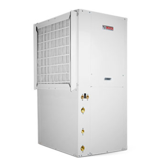
Summary of Contents for Bosch BP Series
- Page 1 CP/BP Series Installation and Maintenance Manual 6 720 220 045 Revised 05-12...
- Page 2 ©Copyright 2012 Bosch, Inc All rights reserved...
-
Page 3: Table Of Contents
CP/BP Series table of contents taBle oF coNteNts Earth Coupled Systems ........15 Model Nomenclature ..........3 Unit Start-up ............15 Initial Inspection ........... 4 Heat Recovery Package ........15 General Description ..........4 Water Tank Preparation ........16 Moving and Storage ..........4 HR Water Piping .......... -
Page 4: Initial Inspection
Units must only be stored or moved in the normal upright position as indicated by the “UP” Be certain to inspect all cartons or crates on each arrows on each carton at all times. If unit stacking is... -
Page 5: Installation
MouNtiNG HoriZoNtal uNits While horizontal units may be installed on any Remove shipping block under blower housing. level surface strong enough to hold their weight, Loosen compressor mounting bolts. they are typically suspended above a ceiling by threaded rods. -
Page 6: Condensate Drain
CP/BP Series condensate drain panels, and replacement of air filters for routine (Heat Pumps are not internally trapped). A vertical maintenance. This will ensure proper work space for air vent is sometimes required to avoid air pockets service personnel to perform maintenance or repair. -
Page 7: Electrical
CP/BP Series electrical electrical capacity to handle the air required for the unit application. If the duct system is too small, larger ductwork should be installed. Check for existing Always disconnect power to the unit before Caution leaks and repair as necessary to ensure a tight air servicing to prevent injury or death due to seal within duct. -
Page 8: Thermostat Connections
30 seconds, the controller will shut down the Thermostat wiring is connected to a 7 position low compressor and enter into a soft lockout voltage terminal block in the electrical box. The condition. - Page 9 The UPM includes the following features: premature failure of the unit. The “TEST” switch must be set back to “NO” for normal operation. • aNti-sHort cycle tiMe—5 minute delay on break timer to prevent compressor short cycling.
-
Page 10: Sequence Of Operation
10 cP/BP series sequence of operation • lockout reset—A hard lockout can be reset by seQueNce oF oPeratioN turning the unit thermostat off and then back on cooling Mode when the “RESET” dip switch is set to “Y” or by... - Page 11 UPM Sequence of Operation (SOO) Flow Chart Y1=1 Power/Switchs/Sensor Status Check 18VAC > Lockout Can Be Set To 4 Via Dip Switch Blink Code On Status LED Soft Lockout HPC = 1 COUNT = 2...
- Page 12 12 cP/BP series sequence of operation Once the thermostat reaches set point thermostats in conjunction with a humidistat are temperature and the humidity is above set point acceptable for use, (Note: “O” output for reversing the unit will operate in the hot gas reheat mode valve energized in cooling mode is required.)
-
Page 13: Fluid Differential Pressure Switch
Fluid differential Pressure switch cP/BP series second heat pump or resistance heat should be runs). Never use fl exible hoses of a smaller inside provided to handle the structural loss load. diameter than that of the water connections on the unit. -
Page 14: Fresh Water Systems
80°F in the heating mode when equipped with the Figure #6 optional extended range. In the cooling mode, heat is rejected from the Bosch unit into the water loop. A When two or more units are supplied from one well, cooling tower provides evaporative cooling to the loop... -
Page 15: Earth Coupled Systems
4. Verify the heat pump is operating in the cooling received specialized training. Utilizing Bosch’s mode. Ground Loop Pumping Package (GLP), makes the installation easy. Anti-freeze solutions are utilized 5. -
Page 16: Water Tank Preparation
16 CP/BP Series Water tank Preparation vents in the heating mode the heat recovery may need 4. Drain tank by opening drain valve on the bottom to be turned off. In the heating mode the heat recovery of the tank, then open pressure relief valve or captures heat that would normally be used for space hot water faucet. -
Page 17: Water Tank Refill
CP/BP Series MaWater Tank Refill MaiNteNaNce Water taNk reFill 1. Filter changes or cleanings are required at 1. Open the cold water supply to the tank. regular intervals. The time period between filter 2. Open a hot water faucet to vent air from the system changes will depend upon type of environment until water flows from the faucet, then close. -
Page 18: In-Warranty Material Return
18 cP/BP series in-Warranty Material return iN-WarraNty Material returN Freight charges for all items returned to the factory shall be prepaid. The return of the part does not When contacting your Representative for service or constitute an order for a replacement. Therefore, a... -
Page 19: Dimensions
Unit Specifications cP/BP series Dimensions Table 2: Vertical Horizontal Supply Air Return Air Replacement Fil- Unit Unit Connection Connection* ter Nominal Size* Model (In) (In) (In) (In) (In) Width Depth Height Width Depth Height Width Height Width Height H: 18.0 H: 15"x20"x1"... -
Page 20: Fluid Pressure Drops
Unit Specifications 20 cP/BP series Fluid Pressure Drops Table 3: Flow Rate Pressure Pressure Flow Rate Pressure Pressure Model Model (GPM) Drop (FOH) Drop (PSI) (GPM) Drop (FOH) Drop (PSI) 0.61 0.51 1.26 0.91 2.11 1.41 10.1 4.38 2.67 16.9 7.34... -
Page 21: Air Temperature Rise/Fall
Unit Specifications cP/BP series Air Temperature Rise/Fall Table 5: COOLING HEATING Entering Fluid Entering Air Temp °F Air Temp Drop °F Entering Air Temp °F Air Temp Rise °F Temp °F 16-8 - 25.1 15.9 - 23.7 14.8 - 22.1 75/63 21.9 - 27.2... -
Page 22: Refrigerant Pressure Ranges
22 cP/BP series Unit Specification Refrigerant Pressure Ranges Table 6: COOLING HEATING Entering Entering Air Temp (Dry Bulb) Entering Air Temp (Dry Bulb) Fluid Fluid Temp Δ T 70 °F 75 °F 80 °F 60 °F 70 °F °F Suction... -
Page 23: Blower Performance
Unit Specifications cP/BP series Blower Performance Table 7: Available External Static Pressure (ins., Gauge. Wet coil and filter included) Model Motor 0.10 0.20 0.30 0.40 0.50 0.60 0.70 0.80 0.90 1.00 1.10 1.20 Speed High BP007 Medium High BP009 Medium... -
Page 24: Typical Wiring Diagrams
24 cP/BP series typical Wiring diagrams tyPical WiriNG diaGraMs 1 stage - 1 Phase - ecM Motor 6 720 220 045 Subject to change without prior notice Revised 05-12... - Page 25 Wiring diagrams 1 stage - 1 Phase - direct drive Motor Revised 05-12 Subject to change without prior notice 6 720 220 045...
- Page 26 Wiring diagrams 26 cP/BP series 1 stage - 1 Phase - direct drive Motor - Hot Gas reheat 6 720 220 045 Subject to change without prior notice Revised 05-12...
- Page 27 Wiring diagrams 1 stage - 1 Phase - ecM Motor - Hot Gas reheat Revised 05-12 Subject to change without prior notice 6 720 220 045...
-
Page 28: Unit Check-Out Sheet
Max Fuse Size (Amps) __________________________________ Volts / Amps_____________________ /______________________ Entering Air Temperature _______________________________ Leaving Air Temperature _______________________________ Bosch Group 601 NW 65th Court Fort Lauderdale, FL 33309 Phone: (954) 776-5471 Fax: (800) 776-5529 http://www.fhp-mfg.com 6 720 220 045 Subject to change without prior notice... -
Page 29: Troubleshooting
Problem Possible Cause Checks and Corrections Entire unit Power Supply Off Apply power, close disconnect does not run Blown Fuse Replace fuse or reset circuit breaker. Check for correct fuses Voltage Supply Low If voltage is below minimum voltage specified on unit data plate, contact local power company. - Page 30 30 cP/BP series troubleshooting Insufficient Unit undersized Recalculate heating and or cooling loads. If excessive, possibly adding insulation and shading will rectify the problem cooling or heating Check for leaks in duct work or introduction of ambient air Loss of conditioned...
- Page 31 Notes cP/BP series Revised 05-12 Subject to change without prior notice 6 720 220 045...
- Page 32 601 N.W. 65th Court, Ft. Lauderdale, FL 33309 Phone: 954-776-5471 | Fax: 954-776-5529 www.boschtaxcredit.com | www.bosch-climate.us...