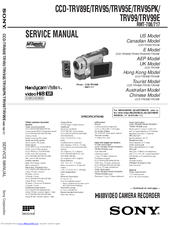
SONY Handycam RMT-708 Service Manuals
Manuals and User Guides for SONY Handycam RMT-708 Service. We have 11 SONY Handycam RMT-708 Service manuals available for free PDF download: Service Manual
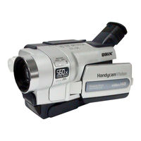
Sony Handycam RMT-708 Service Service Manual (378 pages)
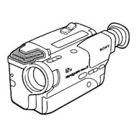
Hi8 Video Camera Recorder
Table of Contents
Advertisement
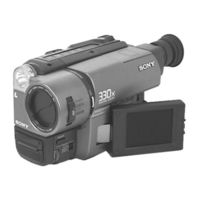
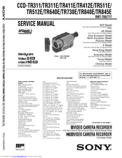
Sony Handycam RMT-708 Service Service Manual (240 pages)
Hi8 VIDEO CAMERA RECORDER
Table of Contents
Advertisement
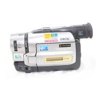
Sony Handycam RMT-708 Service Service Manual (169 pages)
Hi8 Video Camera Recorder
Table of Contents
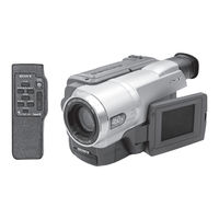
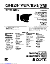
Sony Handycam RMT-708 Service Service Manual (165 pages)
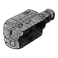
VIDEO CAMERA RECORDER; VIDEO CAMERA RECORDER
Table of Contents
Sony Handycam RMT-708 Service Service Manual (39 pages)
Hi8 video camera recorder
Sony Handycam RMT-708 Service Service Manual (23 pages)
Video camera recorder
Advertisement