Sign In
Upload
Manuals
Brands
Siemens Manuals
Relays
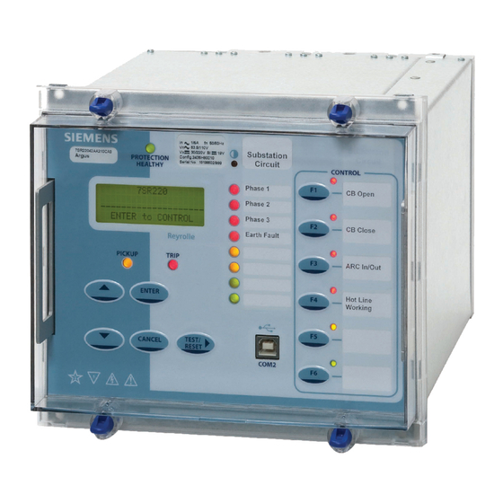
7SR220 Argus
Siemens 7SR220 Argus Manuals
Manuals and User Guides for Siemens 7SR220 Argus. We have
5
Siemens 7SR220 Argus manuals available for free PDF download: Application Manual, Installation Manual, Quick Start Manual, Manual, Configuration Manual
Siemens 7SR220 Argus Application Manual (40 pages)
Brand:
Siemens
| Category:
Relays
| Size: 0.81 MB
Table of Contents
Document Release History
2
Table of Contents
3
Section 1: Common Functions
5
Multiple Settings Groups
5
Figure 1.1-1 Example Use of Alternative Settings Groups
5
Binary Inputs
6
Figure 1.2-1 Example of Transformer Alarm and Trip Wiring
6
Figure 1.2-2 - Binary Input Configurations Providing Compliance with EATS 48-4 Classes
8
Binary Outputs
9
Leds
9
Figure 1.4-1 LED Configuration Via the LED Matrix Tab
9
Figure 1.4-2 LED Configuration Via the Settings \ OUTPUT CONFIG \ LED CONFIG Menu
10
Section 2: Protection Functions
11
Time Delayed Overcurrent (51/51G/51N)
11
Figure 2.1-1 IEC ni Curve with Time Multiplier and Follower DTL Applied
11
Figure 2.1-2 IEC ni Curve with Minimum Operate Time Setting Applied
12
Selection of Overcurrent Characteristics
12
Figure 2.1-3 Reset Delay
13
Reset Delay
13
Voltage Dependent Overcurrent (51V)
14
Cold Load Settings (51C)
14
Instantaneous Overcurrent (50/50G/50N)
15
Blocked Overcurrent Protection Schemes
15
Figure 2.4-1 General Form of DTL Operate Characteristic
15
Figure 2.4-2 Blocking Scheme Using Instantaneous Overcurrent Elements
16
Sensitive Earth-Fault Protection (50SEF)
17
Figure 2.5-1 Sensitive Earth Fault Protection Application
17
Directional Protection (67)
18
Figure 2.6-1 Directional Characteristics
18
Figure 2.6-2 Phase Fault Angles
18
Figure 2.6-3 Application of Directional Overcurrent Protection
19
Figure 2.6-4 Feeder Fault on Interconnected Network
20
Directional Earth-Fault (50/51G, 50/51N, 51/51SEF)
21
Figure 2.7-1 Earth Fault Angles
21
High Impedance Restricted Earth Fault Protection (64H)
22
Figure 2.8-1 Balanced and Restricted Earth-Fault Protection of Transformers
22
Figure 2.8-2 Composite Overcurrent and Restricted Earth-Fault Protection
23
Negative Phase Sequence Overcurrent (46NPS)
24
Undercurrent (37)
24
Thermal Overload (49)
24
Figure 2.11-1 Thermal Overload Heating and Cooling Characteristic
24
Under/Over Voltage Protection (27/59)
25
Neutral Overvoltage (59N)
26
Figure 2.13-1 NVD Application
26
Figure 2.13-2 NVD Protection Connections
26
Application with Capacitor Cone Units
27
Derived NVD Voltage
27
Negative Phase Sequence Overvoltage (47)
27
Under/Over Frequency (81)
28
Figure 2.15-1 Load Shedding Scheme Using Under-Frequency Elements
28
Section 3: CT Requirements
29
CT Requirements for Overcurrent and Earth Fault Protection
29
Overcurrent Protection Cts
29
Earth Fault Protection Cts
29
CT Requirements for High Impedance Restricted Earth Fault Protection
29
Section 4: Control Functions
30
Auto-Reclose Applications
30
Figure 4.1-1 Sequence Co-Ordination
30
Auto-Reclose Example 1
31
Auto-Reclose Example 2 (Use of Quicklogic with AR)
32
Figure 4.1-2 Example of Logic Application
32
Quick Logic Applications
33
Auto-Changeover Scheme Example
33
Figure 4.2-1 Example Use of Quick Logic
33
Section 5: Supervision Functions
34
Circuit-Breaker Fail (50BF)
34
Settings Guidelines
34
Figure 5.1-1 - Circuit Breaker Fail
34
Figure 5.1-2 - Single Stage Circuit Breaker Fail Timing
35
Figure 5.1-3 - Two Stage Circuit Breaker Fail Timing
35
Current Transformer Supervision (60CTS)
36
Voltage Transformer Supervision (60VTS)
37
Trip-Circuit Supervision (74TCS)
38
Trip Circuit Supervision Connections
38
Figure 5.4-1:Trip Circuit Supervision Scheme 1 (H5)
38
Figure 5.4-2:Trip Circuit Supervision Scheme 2 (H6)
39
Figure 5.4-3:Trip Circuit Supervision Scheme 3 (H7)
39
Inrush Detector (81HBL2)
40
Broken Conductor / Load Imbalance (46BC)
40
Circuit-Breaker Maintenance
40
Advertisement
Siemens 7SR220 Argus Installation Manual (24 pages)
Brand:
Siemens
| Category:
Relay
| Size: 0.87 MB
Table of Contents
Document Release History
2
Table of Contents
3
List of Figures
4
Section 1: Installation
5
Unpacking, Storage and Handling
5
Recommended Mounting Position
5
Wiring
5
Earthing
5
Ancillary Equipment
5
Section 2: Equipment Operating Conditions
6
Current Transformer Circuits
6
External Resistors
6
Fibre Optic Communication
6
Front Cover
6
Section 3: Dimensions and Panel Fixings
7
Relay Dimensions and Weight
7
Figure 3.1-1 Overall Dimensions (MM) and Panel Drilling for Size E6 Epsilon Case
7
Figure 3.1-2 Overall Dimensions (MM) and Panel Drilling for Size E8 Epsilon Case
7
Fixings
8
3.2.1 Crimps
8
3.2.2 Panel Fixings
8
Fibre Optic Connectors
8
Section 4: Rear Terminal Drawings
9
E6 Case
9
Figure 4.1-1 E6 Standard Comms (USB Front Port, Rear RS485) (See Note 2)
9
Figure 4.1-2 E6 Standard + Additional Comms (IRIG-B, 2 X F.O. (ST Connectors))
9
Figure 4.1-3 E6 Standard + Additional Comms (IRIG B + RS485) (See Note 2)
10
Figure 4.1-4 E6 Standard + Additional Comms (IRIG B + RS232)
10
E8 Case
11
Figure 4.2-1 E8 Standard Comms (USB Front Port, Rear RS485) (See Note 2)
11
Figure 4.2-2 E8 Standard + Additional Comms (IRIG B, 2 X F.O. (ST Connectors))
11
Figure 4.3-1 E8 Standard + Additional Comms (IRIG B + RS485) (See Note 2)
12
Figure 4.3-2 E8 Standard + Additional Comms (IRIG B + RS232)
12
Section 5: Connection/Wiring/Diagrams
13
Wiring Diagram: 7SR21 OC/EF Relay
13
Figure 5.1-1 Connection Diagram for 7SR21 Relay
13
Wiring Diagram: 7SR22 Directional OC/EF Relay
14
Figure 5.2-1 Connection Diagram for 7SR22 Relay
14
Section 6: Data Comms Connections
15
Standard RS485 Connections
15
IRIG-B Connections
15
Figure 6.1-1 RS485 Data Comms Connections between Relays
15
Additional (Optional) Fibre Optic Connections
16
Figure 6.3-1 Data Comms to Multiple Devices Using 7SG24 and F.O. Star Network
16
Figure 6.3-2 Data Comms to Multiple Devices Using 7SG24 and F.O. Ring Network
16
Additional (Optional) RS485 Connections
17
Additional (Optional) RS232 Connections
17
Figure 6.4-1 RS485 Data Comms Connections between Relays
17
Figure 6.5-1 RS232 Data Comms Pin Connections
17
Additional (Optional) Ethernet Connection for IEC 61850
18
Figure 6.5-1 Ethernet Connection for IEC 61850 (Star Connection)
18
Figure 6.5-1 Ethernet Connection for IEC 61850 (Ring Connection)
18
Section 7: Connection Diagrams
19
Typical Connection: 7SR22 Directional OC/EF and REF
19
Figure 7.1-1 7SR22 Applied to Transformer Incomer
19
Typical Connection: 7SR22 Directional OC/EF and NVD
20
Figure 7.2-1 7SR22 Applied to Transformer Incomer Including HV NVD Protection
20
Typical Connection: 7SR22 Directional OC/EF and NVD
21
Figure 7.3-1 7SR22 Applied to Feeder Including NVD Protection
21
Typical Connection: 7SR22 Directional OC/EF and NVD
22
Figure 7.4-1 7SR22 Applied to Feeder
22
Typical Connection: 7SR22 Directional OC and EF
23
Figure 7.5-1 7SR22 Applied to Feeder - no Zero Sequence Voltage Source
23
Typical Connection: 7SR22 Connected to Vts and Capacitor Cone Unit
24
Figure 7.6-1 7SR22 Applied to Feeder with Capacitor Cones Fitted
24
Siemens 7SR220 Argus Configuration Manual (14 pages)
Brand:
Siemens
| Category:
Relays
| Size: 0.5 MB
Table of Contents
Document Release History
2
Table of Contents
3
Contents
3
Section 1: Introduction
5
Relay Menus and Display
5
Figure 1.1-1 Menu
5
Figure 1.1-2 Fascia Contrast Symbol
5
Figure 1.1-3 Relay Fascia
6
Operation Guide
7
1.2.1 User Interface Operation
7
Figure 1.2-1 Relay Identifier Screen
7
Section 1: Configuring the Relay Using Reydisp Evolution
10
Physical Connection
10
Front USB Connection
10
Figure 2.1-1 USB Connection to a PC
10
Standard Rear RS485 Connection
11
Optional Rear Fibre Optic Connection
11
Figure 2.1-2 Standard Rear RS485 Connection to a PC
11
Figure 2.1-3 Additional (Optional) Rear Fibre Optic Connection to a PC
11
Optional Rear RS485 + IRIG-B Connection
12
Optional Rear RS232 + IRIG-B Connection
12
Figure 2.1-4 Additional (Optional) Rear RS485 + IRIG-B Connection to a PC
12
Configuring Relay Data Communication
13
Connecting to the Relay Via Reydisp Evolution
14
Figure 2.1-6 PC Comm Port Selection
14
Advertisement
Siemens 7SR220 Argus Quick Start Manual (17 pages)
Overcurrent Protection Relay
Brand:
Siemens
| Category:
Relays
| Size: 1.75 MB
Table of Contents
Function Overview
2
User Interface
2
Monitoring Functions
2
Data Communications
3
Description of Functionality
3
Standard Functionality
3
Additional Functionality
5
Optional Functionality
5
Technical Data
6
Inputs and Outputs
6
Mechanical Tests
7
Electrical Tests
7
Environmental Tests
8
Case Dimensions
10
Siemens 7SR220 Argus Manual (17 pages)
Overcurrent Protection Relay, Answers for energy, Reyrolle Protection Devices
Brand:
Siemens
| Category:
Relays
| Size: 2.59 MB
Table of Contents
User Interface
2
Function Overview
2
Monitoring Functions
2
Data Communications
3
Description of Functionality
3
Standard Functionality
3
Additional Functionality
5
Optional Functionality
5
Technical Data
6
Inputs and Outputs
6
Mechanical Tests
7
Electrical Tests
7
Environmental Tests
8
Case Dimensions
10
Advertisement
Related Products
Siemens Argus 7SR21
Siemens Argus 7SR22
Siemens 7SR210 Argus
Siemens 7SR242 Duobias
Siemens 7SR23 DAD
Siemens Argus 7SR11
Siemens Argus 7SR12
Siemens 7SR45 Argus
Siemens 7SR18 Solkor
Siemens 7SR10 Argus Series
Siemens Categories
Industrial Equipment
Controller
Control Unit
Oven
Washer
More Siemens Manuals
Login
Sign In
OR
Sign in with Facebook
Sign in with Google
Upload manual
Upload from disk
Upload from URL