Sign In
Upload
Manuals
Brands
Parkeon Manuals
Vending machines
WAYFARER 6
Parkeon WAYFARER 6 Manuals
Manuals and User Guides for Parkeon WAYFARER 6. We have
1
Parkeon WAYFARER 6 manual available for free PDF download: Service Manual
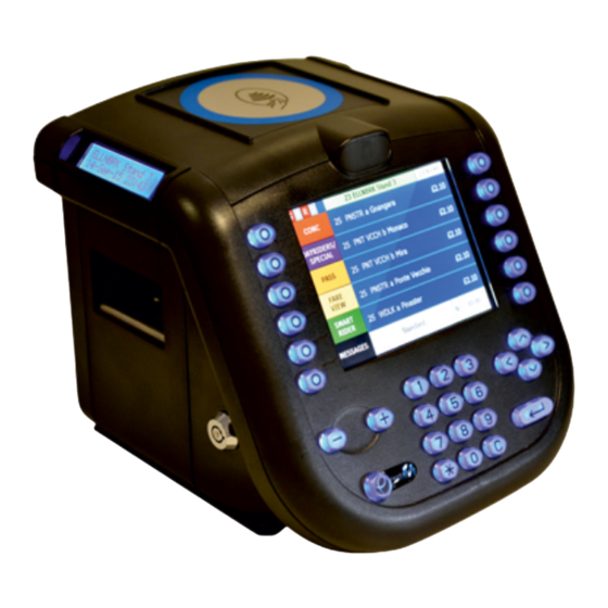
Parkeon WAYFARER 6 Service Manual (127 pages)
ELECTRONIC TICKET MACHINE
Brand:
Parkeon
| Category:
Vending machines
| Size: 7.52 MB
Table of Contents
Table of Contents
4
Introduction
9
Purpose
9
Scope
9
Audience
11
Related Documents
11
Revision History
11
Terms and Abbreviations Used in this Manual
12
Technical Data
13
General
13
Dimensions (Approximate)
13
Electrical
13
Power Supply Cable
14
Communications Cable
14
Ethernet Cable
15
Environmental
15
GPS Antenna (if Fitted)
15
4G Antenna (if Fitted)
15
General Description
16
What Are Gps, Wlan, Wifi and 3G/4G
16
GPS (Optional at Build)
16
WLAN (Optional at Build)
17
WIFI (Optional at Build)
17
4G Data Transfer (Optional at Build)
17
How Does the Etm Use Gps, Wifi and 3G/4G
17
Figure 1. the ETM System and Components
19
Physical Description
20
Detailed Description
22
Keyboard
22
LCD Display
22
Passenger Display
22
Printer and Paper Control Components
22
Data Back-Up Module
23
Card Reader
23
GPS (Optional at Build)
23
4G (Optional at Build)
23
Printed Circuit Boards
24
Model Identification
28
Figure 2. Model and Serial Number Label
28
Installation
29
Figure 3. Wayfarer 6 Installation and Clearance Dimensions
29
Installing the Wayfarer 6 and Tray
30
Fitting the Wayfarer 6 Mounting Tray
31
Figure 4. Typical Wayfarer 6 Mounting Tray (Generic Version)
31
Connecting the Cable Assemblies
33
Wayfarer 6 Tray Interface PCB Connections
33
Figure 5A. the Wayfarer 6 Mounting Tray Interface PCB
34
Figure 5B. the Wayfarer 6 Main Control PCB (Links)
35
Figure 5C. the Wayfarer 6 Printer PCB (Links)
36
Figure 6. Generic Wayfarer 6 Installation Wiring Diagram
37
Wayfarer 6 ETM and Tray Final Operation
38
Maintenance & Repair - General Information
42
Precautions
42
Maintenance Levels
42
Tools and Equipment
43
Obtaining Spare Parts
44
Electronic Mail
44
Returning Machines or Assemblies for Repair
45
Routine Maintenance and Servicing
46
Maintenance Schedule
46
Exterior Cleaning
46
Display Cleaning
47
Lubrication
47
Interior Cleaning
47
Cleaning the Sync Sensor
47
Cleaning the Printer Roller
48
Cleaning the Print Head
49
Replacing the Paper Location Peg
49
Figure 7. Cleaning the Print Head
49
Servicing
50
Changing a Paper Roll
50
Figure 8. Changing a Paper Roll
51
Removing a Paper Blockage
52
Figure 9. Clearing a Paper Jam
52
Special Repair Operations
53
Connector Crimp Terminals
53
Figure 10. Connector Crimp Terminal
53
Removal and Replacement of Parts
54
Introduction
54
The Lid and End Panel
55
Opening the Lid
55
Removing the Wayfarer 6 Retaining Screws
56
Figure 11. the Wayfarer 6 Retaining Screws
56
Removing the Lid and End Panel Section
57
Figure 12. Removing the End Panel / Hinged Lid
57
Figure 13. Accessing the Rear of the Console
58
Removing the Smart Card Antenna PCB
59
Figure 14. Removing the Smart Card Antenna PCB
59
Removing the GPS and Cable Cover
60
Figure 15. Removing the GPS and Cable Cover
60
Removing the 3G/4G (Internal)
61
Figure 16. 3G/4G Antenna Options
61
Console Assembly
62
Removing the Console Assembly
62
Figure 17. Console Fixings (View with Console Detached)
62
Removing the Front Moulding
63
Figure 18. Removing the Front Moulding
63
Removing the Imx53 Processor Board
64
Figure 19. Separating the PCB + Cables Assy
64
Removing the USB Hub Board
65
Removing the (Optional) Expansion Board
65
Removing the Console Control PCB
66
Figure 20. Flat Flexible Cable Removal and Re-Insertion
66
Figure 21. Removing the SAM Expansion and 3G/4G Pcb's
67
Removing the (Optional) SAM Expansion Board
68
Removing the (Optional) 3G/4G PCB
68
Removing the Speaker
68
Removing the Console Serial Number PCB
68
Removing the Display Assy from the Front Moulding
69
Figure 22. Speaker & Serial No. PCB Fixings
69
Figure 23. Display & Keyboard Fixings
70
Removing the Display from the Mounting Plate
71
Figure 24. Wayfarer 6 Console Front Assembly Details
71
Removing the Keyboard PCB / Keycaps / Keymat Assy
72
Figure 25. Display Removal
72
Removing the Keymat and Keycaps
73
Figure 26. Keyboard PCB Removal
73
Figure 27. Keymat and Keycaps Removal
74
Printer Assembly
75
Removing the Printer Assembly
75
Figure 28. Printer Assembly (1) Rear View
75
Removing the Printer PCB
76
Figure 29. Printer Assembly (2) Front View
76
Removing the Synch Disc
77
Removing the Delrin Ball
77
Figure 30. Wayfarer 6 Printer Base Unit
78
Removing the Paper Location Peg
79
Removing the Wayfarer 6 Printer Mechanism
79
Dismantling the Printer Mechanism
79
Figure 31. Dismantling the Wayfarer 6 Printer Mechanism
80
Figure 32. Printout Blade Fitting
81
Figure 33. Paper Guide Fitting
82
Figure 34. Section through Head Lock Lever
83
Figure 35. Print Roller and Motor Fitting
84
Figure 36. Print Head and Lower Paper Guide
86
Figure 37. Print Head Pivot Pins Location
87
Figure 38. Paper out Microswitch Fitting
88
Passenger Display Assembly
89
Removing the Top Display Assembly
89
Figure 39. Printer Assembly with Passenger Display
89
Figure 40. Passenger Display Removal
90
The Sd, Sam, 3G/4G Sim, Wifi & Usb Interfaces
91
Removing the Console Access Cover
91
Figure 41. Location of SD, SAM, GPRS SIM, WIFI & USB Sockets
92
Removal and Insertion of the SD Memory Card
93
Figure 42. SD Memory Card Removal and Re-Insertion
93
Removal and Insertion of the 3G/4G SIM and Sam's
94
Figure 43. 3G/4G SIM / Smart Card SAM Removal and Re-Insertion
94
Wifi Module and Antennas
95
Using the USB Port
95
Fault Finding and Testing
96
General Information
96
Types of Faults
99
Control Board Faults
99
Figure 44. Interconnection Diagram
107
Figure 45. Printer Static Cable Assembly
108
Figure 46. Printer Stepper Motor Drive Cable Assembly
108
Figure 47. Paper out Microswitch Cable Assembly
109
Figure 48. Printer Data Cable Assembly
110
Figure 49. Passenger Display Cable Assembly
111
Figure 50. Data Graphics Cable Assembly
112
Figure 51. SC Antenna PCB to BH Cable Assembly
113
Figure 52. SC (Control Board) to BH Cable Assembly
113
Figure 53. 3G/4G Antenna to BH Cable Assembly
114
Figure 54. 3G/4G (Control Board) to BH Cable Assembly
115
Figure 55. GPS Antenna to BH Cable Assembly
115
Figure 56. GPS (Control Board) to BH Cable Assembly
116
Figure 57. 37 Way Control Ribbon Cable Assembly
117
Figure 58. Console Speaker Cable Assembly
118
Figure 59. Serial Number PCB Cable Assembly
118
Figure 60. Printer BH Cable Assembly
119
Figure 61. Keyboard 50 Way Display Cable Assembly
120
Figure 62. Keyboard 20 Way Keys Cable Assembly
121
Figure 63. Keyboard 40 Way Display Cable Assembly
122
Figure 64. Wayfarer 6 ETM and Tray Exploded View (Generic)
124
Figure 65. Ticket Paper Specification
127
Advertisement
Advertisement
Related Products
Parkeon Categories
Automobile Electronics
Digital Signage
Vending machines
More Parkeon Manuals
Login
Sign In
OR
Sign in with Facebook
Sign in with Google
Upload manual
Upload from disk
Upload from URL