Sign In
Upload
Manuals
Brands
Mitsubishi Manuals
Gateway
GOT2000Series
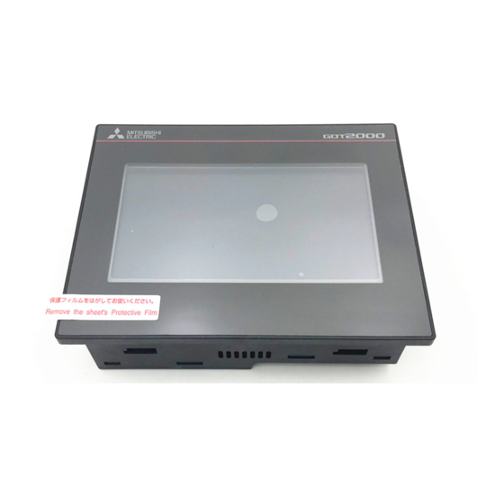
Mitsubishi GOT2000Series Manuals
Manuals and User Guides for Mitsubishi GOT2000Series. We have
1
Mitsubishi GOT2000Series manual available for free PDF download: Connection Manual
Mitsubishi GOT2000Series Connection Manual (338 pages)
GRAPHIC OPERATION TERMINAL
Brand:
Mitsubishi
| Category:
Gateway
| Size: 8.84 MB
Table of Contents
Introduction
10
Safety Precautions
3
Table of Contents
10
List of Manuals for GT Works3
18
Abbreviations and Generic Terms
19
1 Preparatory Procedures for Monitoring
23
Setting the Communication Interface
25
Setting Connected Equipment (Channel Setting)
25
I/F Communication Setting
31
Precautions
33
Writing the Project Data and os Onto the GOT
34
Checking the Project Data and os Writing on GOT
35
Option Devices for the Respective Connection
36
Communication Module
36
Conversion Cable
37
Option Unit
37
Serial Multi-Drop Connection Unit
37
Installing a Unit on Another Unit (Checking the Unit Installation Position)
38
Connection Cables for the Respective Connection
41
GOT Connector Specifications
41
Coaxial Cableconnector Connection Method
42
Terminating Resistors of GOT
43
Verifying GOT Recognizes Connected Equipment
44
Checking for Normal Monitoring
46
Check on the GOT
46
Confirming the Communication State on the GOT Side (for Ethernet Connection)
48
Confirming the Communication State to each Station (Station Monitoring Function)
50
Connections to Non-Mitsubishi Products
53
Connection to
55
2 Connection to Hitachi Ies Plc
55
Connectable Model List
56
System Configuration
57
Connection to Large-Sized H Series
57
Connecting to H-200 to 252 Series, H Series Board Type or EH-150 Series
59
Connection Diagram
61
Cable
61
GOT Side Settings
63
PLC Side Setting
65
Device Range that Can be Set
66
HITACHI HIDIC H Series
68
Connection to Hitachi Plc
69
Connectable Model List
70
System Configuration
71
Connecting to S10Mini
72
Connection Diagram
73
GOT Side Settings
74
PLC Side Setting
75
Device Range that Can be Set
76
Connection to Fuji Plc
79
Connectable Model List
80
System Configuration
81
Connecting to MICREX-F70
83
Connecting to MICREX-F120S/140S/15[]S
86
Connection Diagram
89
RS-485 Cable
90
GOT Side Settings
91
PLC Side Setting
92
Connecting to NC1L-RS4
93
Connecting to FFU120B
94
Connecting to FFK120A-C10
95
Station Number Setting
96
Device Range that Can be Set
97
Precautions
99
Connectable Model List
102
Connecting to PXR3, PXR4, PXR5 or PXR9
103
System Configuration
103
Connecting to PXG4, PXG5, PXG9 or PXH9
104
Connection Diagram
107
Cable
107
RS-485 Cable
108
GOT Side Settings
112
Communication Detail Settings
112
Setting Communication Interface (Communication Settings)
112
Temperature Controller Side Setting
114
Connecting to PXG4, PXG5 or PXG9
114
Connecting to PXR3/4/5/9
114
Connecting to Interface Converter (RC-77)
115
Connecting to PXH9
115
Connecting to Interface Converter (SI-30A)
116
Connecting to Interface Converter (K3SC-10)
117
Connecting to Interface Converter (KS-485)
117
Station Number Setting
118
Device Range that Can be Set
119
Fuji Pxr/Pxg/Pxh
120
Precautions
120
6 Connection to Yaskawa Plc
121
Connectable Model List
122
Serial Connection
123
System Configuration for Connecting to GL120 or GL130
123
System Configuration for Connecting to GL60S, GL60H or GL70H
124
System Configuration Ffor Connecting to MP-920/930, CP-9300MS/9200(H) for PROGIC-8
125
System Configuration for Connecting to CP-9200SH, CP-317
128
System Configuration for Connecting to MP2200, MP2300 or MP2300S
129
Connection Diagram
130
GOT Side Settings
133
PLC Side Settings
134
Ethernet Connection
137
System Configuration for Connecting to MP-920 or MP2200 or MP2300 or MP2300S or CP-9200SH or CP-312 or CP-317
137
GOT Side Settings
138
GOT Ethernet Setting
139
PLC Side Setting (MP2000 Series, MP920 Series)
140
PLC Side Setting (CP-9200SH Series, CP-312, CP-317 Series)
144
Precautions
147
Device Range that Can be Set
148
Yaskawa Gl/Progic8
148
Yaskawa Cp9200 (H)
149
Yaskawa Cp9200Sh/Mp900
149
YASKAWA MP2000/MP900/CP9200SH Series
150
Connectable Model List
152
Serial Connection
153
System Configuration for Connecting to FA500
155
Connection Diagram
156
GOT Side Settings
158
PLC Side Setting
159
Connecting to CPU Port/D-Sub 9-Pin Conversion Cable, SIO Port Adapter Cable
160
Connecting PC Link Module (F3LC11-1F, F3LC12-1F)
161
Connecting PC Link Module (LC01-0N, LC02-0N)
162
Connecting to STARDOM
163
Precautions
165
Ethernet Connection
166
GOT Side Settings
167
PLC Side Setting
169
Connecting to Ethernet Interface Module (F3LE12-0T)
170
Connecting to F3SP66, F3SP67, F3SP71-4N (Built-In Ethernet Interface)
171
Device Range that Can be Set
172
YOKOGAWA FA500/FA-M3 Series
173
Connection to Yokogawa Temperature Controller
175
Connectable Model List
176
Connection to Yokogawa Temperature Controller
176
System Configuration
177
Connecting to UT100 Series
179
Connecting to UT2000 Series
180
Connecting to Utadvanced Series
182
Connection Diagram
186
RS-485 Cable
187
GOT Side Settings
201
Temperature Controller Side Setting
203
Connecting to UT100 Series
204
Connecting to RS232C/RS485 Converter (ML2-[])
205
Station Number Setting
206
Device Range that Can be Set
207
Precautions
208
Connectable Model List
210
System Configuration
212
Connecting to H-PCP-A or H-PCP-B
215
Connecting to SRZ
217
Connecting to CB Series (CB100, CB400, CB500, CB700, CB900)
220
Connecting to FB Series (FB100, FB400 or FB900)
222
Connecting to RB Series (RB100, RB400, RB500, RB700, RB900)
226
Connection to PF900/901, HA400/401, HA900/901, RMC500, MA900/901, AG500 SA100/200
228
Connection to THV-A1
231
Connection to SRX
234
Connecting to SB1
235
Connecting to B400
237
Connection Diagram
238
RS-422 Cable
239
RS-485 Cable
241
GOT Side Settings
247
Temperature Controller Side Setting
249
Connecting to H-PCP-A, H-PCP-B
250
Connecting to Z-TIO, Z-DIO, Z-CT
251
Connecting to Z-COM
252
Connecting to CB Series
253
Connecting to RB Series
254
Connecting to AG500
255
Connecting to SA100/SA200
256
Connecting to SB1
257
Station Number Setting
258
Device Range that Can be Set
260
RKC SR Mini HG
261
Connection to
263
Connectable Model List
264
Serial Connection
266
System Configuration for Connecting to Micrologix1000/1200/1500 Series
267
System Configuration for Connecting to Control/Compact/Flexlogix Series
268
Connection Diagram
269
GOT Side Settings
270
PLC Side Setting
272
Ethernet Connection
273
GOT Side Settings
274
PLC Side Setting
276
Device Range that Can be Set
277
Ab Slc500
278
AB Micrologix1000/1200/1500 Series
279
Connection to Ge Plc
281
Connectable Model List
282
System Configuration
283
Connecting to Series90-70
286
Connecting to Versamax Micro
287
Connection Diagram
289
RS-422 Cable
290
GOT Side Settings
292
PLC Side Setting
293
Connecting to IC693CMM311
294
Device Range that Can be Set
295
Connection to
297
Connectable Model List
298
System Configuration
299
Connecting to K300S
302
Connection Diagram
303
GOT Side Settings
305
PLC Side Setting
306
Device Range that Can be Set
307
Connectable Model List
310
System Configuration
310
GOT Side Settings
311
PLC Side Setting
312
Contents
312
Device Range that Can be Set
313
Connectable Model List
316
Serial Connection
317
System Configuration for Connecting to SIMATIC S7-200
318
Connection Diagram
319
GOT Side Settings
320
PLC Side Setting
321
Connecting to SIMATIC S7-200
322
Ethernet Connection
323
GOT Side Settings
325
PLC Side Setting
327
Precautions
328
Device Range that Can be Set
329
SIEMENS S7-300/400 Series
331
Advertisement
Advertisement
Related Products
Mitsubishi GOT2000 Series
Mitsubishi GOT1000 Series
Mitsubishi GOT1000 GT15
Mitsubishi GOT1000 GT11
Mitsubishi GOT 1000
Mitsubishi GOT-A900 Series
Mitsubishi Galant 1997
Mitsubishi G340
Mitsubishi GB400
Mitsubishi GB17GPV
Mitsubishi Categories
Air Conditioner
Controller
Projector
Automobile
Engine
More Mitsubishi Manuals
Login
Sign In
OR
Sign in with Facebook
Sign in with Google
Upload manual
Upload from disk
Upload from URL