Sign In
Upload
Manuals
Brands
Honeywell Manuals
Security System
VISTA-128FBPN
Honeywell VISTA-128FBPN Manuals
Manuals and User Guides for Honeywell VISTA-128FBPN. We have
1
Honeywell VISTA-128FBPN manual available for free PDF download: Installation And Setup Manual
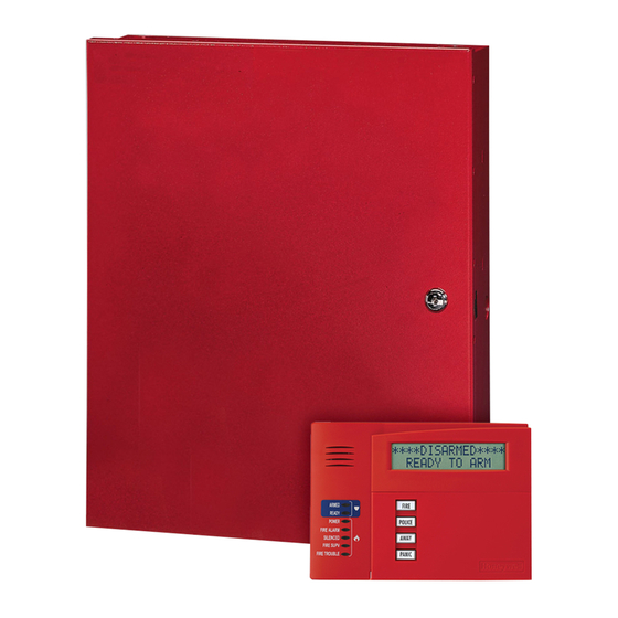
Honeywell VISTA-128FBPN Installation And Setup Manual (128 pages)
Commercial Fire and Burglary Partitioned Security System with Scheduling
Brand:
Honeywell
| Category:
Security System
| Size: 0.96 MB
Table of Contents
Table of Contents
3
Conventions Used in this Manual
7
General Requirements
9
Programming Field Settings for UL864 Compliance
9
Section 1
15
About the VISTA-128FBPN
15
Features
15
Guidelines for Wiring a System
17
Figure 1-1: Isolating Fire Devices from Burglary Devices
18
Section 2
19
Theory of Partitioning
19
Setting-Up a Partitioned System
19
Common Lobby Logic
19
Master Keypad Setup and Operation
21
Section 3
23
Mounting the Control Cabinet
23
Installing the Cabinet Lock
23
Mercantile Premises Listing Guidelines
23
Figure 3-1: Installing the Lock
23
Mercantile Safe and Vault Listing Guidelines
24
Commercial Fire Guidelines
24
Figure 3-2: Cabinet Attack Resistance Considerations
24
Figure 3-3: Commercial Fire Installation Considerations
24
Installing the Control's Circuit Board
25
Installing the Keypads
25
Figure 3-4: Mounting the PC Board
25
Installing External Sounders
26
Figure 3-5: Keypad Connections to Control Panel
26
Figure 3-6. ECP Isolator Wiring
26
Figure 3-7: Intentionally Left Blank
26
Auxiliary Relay Connections
30
Figure 3-8: Wiring Auxiliary Relay for Alarm Activation
30
Figure 3-9: Wiring Auxiliary Relay for Smoke Detector Reset
30
Telephone Line Connections
31
Main Dialer Connections
31
Wiring Burglary and Panic Devices to Zones 1-8
32
Figure 3-10: 2-Wire Smoke Detector on Zone 1 (for Zone 2 Use Terminals 17 and 18)
33
Figure 3-11: 4-Wire Smoke Detectors
34
Figure 3-13: Wiring a Normally Closed Sensor Loop for Tamper Supervision
35
Figure 3-12. Wiring Latching Glassbreaks to Zone 8
35
Installing V-Plex Devices
36
Figure 3-14: Wiring a Normally Open Sensor Loop for Tamper Supervision
36
Figure 3-15: Polling Loop Connections to the Control Panel
38
Figure 3-16: Polling Loop Connections Using One 4297 Extender Module
38
Wireless Zone Expansion
39
Figure 3-17: Polling Loop Connections Using Multiple Extender Modules
39
Figure 3-18: Installing the 5881ENHC with Tamper Protection
41
Installing Output Devices
43
Figure 3-20: 4204 Relay Module
43
Installing a Remote Keyswitch
44
Figure 3-21: 4204CF Relay Module
44
Installing a Remote Keypad Sounder (for Commercial Burglary Use Only)
45
Figure 3-22: Remote Keyswitch Wiring
45
Figure 3-23: Remote Keypad Sounder Wiring
45
Communicators Connected to the ECP
46
Event Log Connections
47
Figure 3-24: Wiring Communicator to Keypad Terminals
47
Connecting the Transformer
48
Earth Ground Connections
48
Determining the Control's Power Supply Load
49
Determining the Size of the Standby Battery
51
Figure 3-25: Connecting the Backup Batteries
52
Section 4
53
Program Modes
53
Entering and Exiting Programming Mode
53
Data Field Programming Mode
53
#93 Menu Mode Programming
54
Zone Number Designations
56
Zone Response Type Definitions
58
Zone Input Type Definitions
60
Programming for Communicator
61
Section 5
63
About Data Field Programming
63
Programming Data Fields
63
Ignore Expansion Zone Tamper
65
Intelligent Test Report
65
Test Report Interval
65
Event Display Lock
76
Section 6
79
Scheduling Options
79
Time Window Definitions
80
Open/Close Schedules Definitions
81
Scheduling Menu Mode
82
Time Windows
83
Daily Open/Close Schedules
84
Holiday Schedules
84
Time-Driven Events
85
Limitation of Access Schedules
89
Temporary Schedules
90
User Scheduling Menu Mode
92
Section 7
93
General Information
93
Unattended Download (for Burglary Use Only)
93
Getting On-Line with a Control Panel
95
Scheduled Download (for Burglary Use Only)
95
Direct-Wire Downloading
96
Telco Handoff
96
Figure 7-1: Direct-Wire Downloading Connections
96
Section 8
97
General Information
97
Setting the Time and Date
97
Section 9
99
General Information
99
User Codes and Levels of Authority
99
Multiple Partition Access
100
Adding a Master, Manager, or Operator Code
101
Changing a Master, Manager, or Operator Code
102
Deleting a Master, Manager, or Operator Code
102
Exiting the User Edit Mode
102
Section 10
103
Battery Test
103
Dialer Test
103
Fire Drill Test (Code + [#] + 69)
103
One-Man Fire Walk-Test (Code + [#] + 68)
103
Burglary Walk-Test
104
Armed Burglary System Test
105
Testing Wireless Transmitters
105
Trouble Conditions
106
To the Installer
107
Appendix A
109
Appendix A
109
UL Installation Requirements
109
UL864/NFPA Local Fire
109
UL864/NFPA Central Station and Remote Station Fire
109
Commercial Burglary Requirements
109
UL609 Local Mercantile Premises/Local Mercantile Safe & Vault
110
UL365 Police Station Connected Burglar Alarm
110
UL1610 Central Station Burglary Alarm
110
Summary of System Commands
113
Specifications
115
Appendix D
117
Appendix C
117
Appendix B
117
Appendix C
117
Appendix D
117
Table of Contact ID Event Codes
117
Event Log Alpha Descriptors
118
Advertisement
Advertisement
Related Products
Honeywell VISTA-128FBP
Honeywell Ademco VISTA-128FB
Honeywell VISTA-128SIA
Honeywell VISTA-128BP
Honeywell VISTA-128BPTSIA
Honeywell VISTA-128BPT
Honeywell VISTA-128FBPT
Honeywell VISTA-128BPEN
Honeywell ADEMCO VISTA-12A
Honeywell ADEMCO Vista-12C
Honeywell Categories
Thermostat
Controller
Control Unit
Security Camera
Accessories
More Honeywell Manuals
Login
Sign In
OR
Sign in with Facebook
Sign in with Google
Upload manual
Upload from disk
Upload from URL