Sign In
Upload
Manuals
Brands
Gamatronic Manuals
UPS
Centric 200 kVA
Gamatronic Centric 200 kVA Manuals
Manuals and User Guides for Gamatronic Centric 200 kVA. We have
3
Gamatronic Centric 200 kVA manuals available for free PDF download: User Manual, Installation Manual
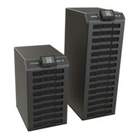
Gamatronic Centric 200 kVA User Manual (85 pages)
UPS system
Brand:
Gamatronic
| Category:
UPS
| Size: 2.75 MB
Table of Contents
Table of Contents
3
1 Introduction
11
Figure 1: Major Components of the Centric
12
LCD Control Panel
13
Figure 2: System Control Panel, Displaying the Main Menu
13
Figure 3: System Control Panel, with Current Navigation Path
13
System Controller
14
UPS Module (25 Kva / 25 Kw)
14
Static Switch Module
14
Battery
14
Table 1: Battery Lifetime Vs Environmental Temperature as Per Eurobat
14
Emergency Power off - EPO (Manual)
15
Battery Trip Coil
15
EPO Indication
15
2 Operating Modes
16
Normal Operation
16
Battery Operation
16
Bypass Operation
16
3 User Interface
17
Control Panel
17
Figure 4: the Control Panel
17
Calibrating the Touch Screen
18
Alarm off Button
18
CPU On/Off Button
18
USB1 and USB2 Connectors
18
4 Centric Control System
19
The Main Screen (Main Menu)
19
Figure 5: the Main Screen and Its Features
19
Table 2: Features of the Main Screen
19
Main Menu Highlights
21
Setup
21
Dry Contacts
21
Time
21
Operation
22
Figure 6: the Operation Submenu
22
Figure 7: the "Turn off / On" Submenu
22
Turning the UPS on
22
Figure 10: the System Requests Confirmation
23
Figure 8: the System Requests Confirmation
23
Figure 9: the "Turn off / On" Submenu
23
Turning the UPS off
23
Status
24
Figure 11: the Status Screen
24
Profile
25
Log
25
Time
25
Help
25
Operating the System
26
Turning the UPS on
26
Turning the UPS off
26
Transferring the Load to Bypass
26
Transferring the Load to the Inverter
26
5 Centric Start - up
27
Normal (Not First-Time) Start-Up
27
Figure 12: Main Menu, UPS Off, Normal Mode
27
Centric Total Shutdown (no Ac Output)
28
6 Centric Menu Functions in Detail
29
Figure 13: Centric Main Menu
29
SETUP Menu
30
Figure 14: "Setup" Menu
30
Figure 15: "Setup > SYSTEM" Options
31
Setup > SYSTEM
31
Setup > System > NOMINAL SETTINGS
31
Setup > System > CONTROLLER
32
Setup > System > NUMBER of BATTERIES
32
Setup > System > SHUTDOWN and AUTORESTART
32
Setup > System > SYSTEM TYPE
32
Figure 16: "Setup > Modules" Options
33
Setup > MODULES
33
Setup > Modules > AC INPUT VOLTAGE CALIBRATION
33
Setup > Modules > AC OUTPUT VOLTAGE CALIBRATION
33
Setup > Modules > MODULES INPUT CURRENT CALIBRATION
33
Setup > Modules > AC OUTPUT VOLTAGE ADJ
34
Setup > Modules > BATTERY VOLTAGE CALIBRATION
34
Setup > Modules > DC VOLTAGE CALIBRATION
34
Setup > Modules > MODULES OUTPUT CURRENT CALIBRATION
34
Setup > Modules > SERIAL NUMBER
34
Figure 17: "Setup > Battery" Options
35
Setup > BATTERY
35
Setup > Battery > BATTERY TEST PARAMETERS
35
Setup > Battery > BATTERY CURRENT
36
Setup > Battery > BATTERY CAPACITY in Ah
37
Setup > Battery > BATTERY TEMPERATURE CONTROL
37
Figure 18: "Setup > Static Switch" Options
38
Setup > ST.SW. > CALIBRATE BYPASS VOLTAGE
38
Setup > ST.SW. > CALIBRATE INVERTER VOLTAGE
38
Setup > ST.SW. > CALIBRATE OUTPUT CURRENT
38
Setup > ST.SW. > CALIBRATE OUTPUT VOLTAGE
38
Setup > STATIC SWITCH
38
Setup > ST.SW. > HIGH-LEVEL SETUP
39
Setup > ST.SW. > OVERLOAD HYSTERISIS
39
Figure 19: "Setup > Alarms" Options
41
Setup > ALARMS
41
Setup > Alarms > ALARM LIMITS
41
Setup > Alarms > SET ALARM PRIORITIES
41
Figure 20: "Setup > Connectivity" Options
43
Network Configuration Options
43
Setup > CONNECTIVITY
43
Figure 21: Setup > Connectivity > SNMP Configuration Options
44
Figure 22: Creating a New Community
44
SNMP Configuration Options (Optional Feature)
44
Figure 23: Community Name Accepted
45
Serial Communication (Optional Feature)
45
Figure 24: Defining Serial Communication Parameters
46
Figure 25: Defining Modbus Communication Parameters
47
Modbus (Optional Feature)
47
Figure 26: Remote Shutdown Submenu
48
Remote Shutdown (Optional Feature)
48
Figure 27: New Shutdown Destination
49
Figure 28: Select the Shutdown Target and Press the Arrow
49
Figure 29: Remote Shutdown Menu with Target Destination Added
50
Figure 30: Shutdown Destination Screen
50
Email Configuration (Optional Feature)
51
Figure 31: Example of Email Message Body
51
Figure 32: the Email Configuration Menu
52
Table 3: Description of Email Parameters
52
Figure 33: "Add New Recipient" Line
53
Figure 34: New Email Recipient Screen
53
Figure 35: Alarms Button on Email Recipient Screen
53
Figure 36: Alarm Selection Screen for Email Recipient
54
Figure 37: "Setup > Time" Options
55
Setup > TIME
55
Setup > Time > ADJUST DATE / TIME
55
Setup > Time > CHANGE TIME ZONE
55
Setup > Time > SET LAST MAINTENANCE DATE
55
Figure 38: Assigning a Site ID
56
Setup > ASSIGN SITE ID
56
Figure 39: "Setup > Dry Contacts" Option
57
Setup > DRY CONTACTS (Optional Feature)
57
Setup > Dry Contacts > INPUT DRY CONTACTS
57
Figure 40: Defining an Input Dry Contact
58
Setup > Dry Contacts > OUTPUT DRY CONTACTS
58
Table 4: Alarms that Can Trigger Output Dry Contacts
59
Figure 41: Example of an Output Dry Contact Linked to an Alarm
60
Figure 42: "Setup > Save & Restore" Options
62
Setup > SAVE & RESTORE
62
Setup > Save & Restore > RESTORESETTINGS
62
Setup > Save & Restore > SAVESETTINGS
62
Setup > Save & Restore >RESTORE FACTORY SETTINGS
62
Figure 43: "Setup > Password
63
Figure 44: "Setup > Authorization" Option
63
Setup > Authorization > ENABLE / DISABLE REMOTE CONTROL
63
Setup > Authorization > SET USER AUTHORIZATION LEVEL
63
Setup > CHANGE AUTHORIZATION LEVEL
63
Setup > CHANGE PASSWORD
63
Operation
64
Figure 45: the "Operation" Option on the Main Menu
64
Operation > SWITCH ON/OFF
64
Operation > Switch On/Off > CONTROLLER RESTART
64
Operation > Switch On/Off > MODULES off
64
Operation > Switch On/Off > SYSTEM off
64
Operation > Switch On/Off > SYSTEM on
64
Operation > BATTERY TEST
65
Operation > TRANSFER LOAD
65
Operation > Transfer Load > TRANSFER LOAD to BYPASS
65
Operation > Transfer Load > TRANSFER LOAD to INVERTER
65
Status
66
Figure 46: "Main Menu > Status" Option
66
Figure 47: the Status Screen
66
Table 5: Key to Figure 47 (the Status Screen)
67
Profile
68
Figure 48: "Main Menu > Profile" Options
68
Profile > BATTERY
68
Profile > SYSTEM
68
Profile > ALARMS
69
Profile > IDENTIFICATION
69
Profile > ST.SW
69
Log
70
Figure 49: "Main Menu > Log" Options
70
Table 6: Log Message Types
70
Figure 50: Listing of the Logfile Contents
71
Figure 51: Log Record - Detailed Display
72
Figure 52: "Alarms" Display from the Log Detail Screen
73
The "Alarms" Button on the Log Detail Screen
73
Connectivity
74
Figure 53: "Main Menu > Connectivity" Option
74
Figure 54: "Connectivity" Display from Main Menu
74
Time
75
Figure 55: "Main Menu > Time" Option
75
Figure 56: the "Time" Function on the Main Menu
75
Language
76
Help
76
Figure 57: "Main Menu > Language" Option
76
Figure 58: "Main Menu > Help" Option
76
7 Rear Panel Connectors
77
Figure 59: Rear Panel with Connectors
77
Table 7: Key to Figure 59
77
Figure 60: Close-Up of Connector Group 1
78
Figure 61: Close-Up of Connector Group 2
78
Figure 62: Pin Usage in D9 Alarm Connector (in Connector Group 2)
78
8 Troubleshooting
79
9 Periodic Preventive Maintenance
81
10 The Built - in Web Interface ( Option )
82
Preliminaries to Use of the Web Interface
82
11 Centric Specifications
83
Table 8: Technical Specifications
83
Advertisement
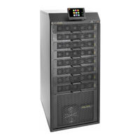
Gamatronic Centric 200 kVA User Manual (117 pages)
UPS SYSTEM
Brand:
Gamatronic
| Category:
UPS
| Size: 5 MB
Table of Contents
S Afety P Recautions
9
System Structure
11
Figure 1: Major Components of the Centric (200 and 100 Kw Models)
12
Figure 2: Major Components of the Centric (50 Kw Model)
13
Lcd Control Panel
14
System Controller
15
Emergency Power off – EPO (Manual)
16
O Perating Modes
17
Normal Mode
17
Battery Mode
17
Bypass Mode
17
Control Panel
18
Buttons and Leds on the System Controller
19
Fallback Push-Button Control Panel
20
C Entric Control System
21
Main Menu Highlights
22
Operation
23
Figure 11: the System Requests Confirmation
24
Status
25
Profile
26
Turning the Ups on
27
Turning the Ups off
27
C Entric Start - up
28
Centric Total Shutdown (no Ac Output)
29
C Entric Menu Functions in Detail
30
Setup Menu
31
Figure 19: "Setup > SYSTEM" Options
32
Table 3: Watchdog Status and the State of the "CPU Active" LED
35
Setup > MODULES
36
Setup > BATTERY
38
Setup > STATIC SWITCH
42
Setup > ALARMS
44
Setup > CONNECTIVITY
45
Figure 25: Setup > Connectivity > SNMP Configuration Options
46
Figure 28: Defining Serial Communication Parameters
47
Figure 29: Defining Modbus Communication Parameters
48
Table 4: Holding Registers for Modbus Queries
49
Figure 30: Remote Shutdown Submenu
61
Figure 31: New Shutdown Destination
62
Figure 34: Shutdown Destination Screen
63
Figure 36: the Email Configuration Menu
64
Figure 37: "Add New Recipient" Line
65
Setup > TIME
66
Setup > ASSIGN SITE ID
67
Setup > DRY CONTACTS (Optional Feature)
68
Figure 44: Defining an Input Dry Contact
69
Table 6: Alarms that Can Trigger Output Dry Contacts
70
Figure 45: Example of an Output Dry Contact Linked to an Alarm
71
Setup > SAVE & RESTORE
72
Setup > CHANGE AUTHORIZATION LEVEL
73
Operation
74
Operation > TRANSFER LOAD
75
Status
76
Table 7: Key to Figure 50 (the Status Screen)
77
Profile
79
Profile > ST.SW
80
Figure 52: "Main Menu > Log" Options
81
Figure 53: Listing of the Log File Contents
82
The "Alarms" Button on the Log Detail Screen
83
Connectivity
84
Time
85
Language
86
M Inor Rear Panel Connectors
87
Figure 63: Close-Up of Connector Group 1
88
Figure 64: Close-Up of Connector Group 2
89
O Perating the Maintenance Bypass Switch
90
Putting the UPS in Maintenance Bypass Mode
91
Returning the Ups to Normal Operation
92
T Roubleshooting
93
Table 11: Troubleshooting Table
94
Troubleshooting "DC High
99
Troubleshooting "DC Low
100
Troubleshooting "Bypass Mode
101
Troubleshooting "UPS Modules
102
Figure 70: Shutdown Reason in Hex, and Fault_Word
103
Figure 71: Structure of Fault_Word
104
Figure 72: Structure of Shutdown_Reason
105
Figure 73: the "Detail 2" or "Technician Data 2" Screen
106
Figure 75: Calibration Menu
107
Troubleshooting "No Output
109
Troubleshooting "Static Switch
110
Figure 78: Voltage and Current Msmts. on the Inverter Output Tab
111
Figure 81: Setup > STSW > High-Level Setup
112
P Eriodic Preventive Maintenance
113
C Entric Specifications
114
Gamatronic Centric 200 kVA Installation Manual (77 pages)
Brand:
Gamatronic
| Category:
UPS
| Size: 8.25 MB
Table of Contents
Table of Contents
3
1 Safety Precautions
7
Do's
7
Don'ts
8
2 System Structure
9
Figure 1: Major Components of the Centric (200 and 100 Kw Models)
9
Figure 2: Major Components of the Centric (50 Kw Model)
10
3 Installation
11
Installation Checklist
11
Installation Procedure
13
Visual Inspection
13
Site Preparation - Physical
13
Figure 3: Recommended Clearances Around the Centric UPS
14
Table 1: Recommended Clearances
14
Site Preparation - Electrical
15
Cabling
15
Figure 4: Main Power Terminals on the Rear of the Centric
17
Figure 5: Close-Up of the Main Terminals (200 Kw Model)
18
Figure 6: Close-Up of the Main Terminals (100 Kw Model)
18
Figure 7: Close-Up of the Main Terminals (50 Kw Model)
19
Figure 8: Recommended Standard System Connections
21
Figure 9: Recommended System Connections, with Input Isolation Transformer
22
Table 2: Maximum Input Currents
23
Table 3: Recommended Circuit Breaker / Switch Ratings
24
Figure 10: Attaching the Cable Stress Reliever
25
Figure 11: Attaching the Cable Stress Reliever - Another View
25
Table 4: Minimum Recommended Size of Battery Cables
26
Figure 12: Connecting the Battery Cabinet to the UPS
27
Powering-Up the System
28
Table 5: Battery Lifetime Vs Environmental Temp. (Illustrative, as Per Eurobat)
28
Initial Configuration
29
Figure 13: Initial Configuration Wizard, "Start" Screen
29
Figure 14: Initial Config. Wizard: Password Entry
29
Figure 15: Initial Config. Wizard: Number of Battery Sets
30
Figure 16: Initial Config. Wizard: Battery Capacity in Ah
30
Figure 17: Initial Config. Wizard: Set Time Zone
31
Figure 18: Finish Configuration Wizard
31
Continuing First-Time Start-Up Process
32
Figure 19: the "Alarms" Icon Indicates Alarm Conditions
32
Define the IP Address of Centric
33
Figure 20: IP Address Configuration
33
Testing
34
Blackout Test
34
Test under Load
34
Check IP Communication with Controller
34
Figure 21: Network Connections Screen
34
Figure 22: Local Area Connection Properties Screen
35
Figure 23: Internet Protocol (TCP/IP) Properties Screen
36
4 Miscellaneous Connections
37
Figure 24: Minor Connector Groupings on the Centric Rear Panel
37
Input and Output Dry Contacts
38
Figure 25: Closer View of Dry Contact Terminals in Connector Group 1
38
Figure 26: Close-Up of Connector Group 2
39
Figure 27: Pin Numbers in D9 Connectors
39
Table 6: D9 Pin Assignments in Connector Group 2
39
Emergency Power off - EPO (Manual)
40
Figure 28: Connections for EPO Switch and Battery Trip Coil
40
5 Parallel Operation
41
Theory
41
Decentralized Static Switch Method
41
Figure 29: the Static Switch in Context (Stand-Alone System)
41
Parallel Communication
42
Figure 30: Parallel Comm. Connections (Cable Cat.no. GPIN15350)
42
Current Sharing
43
Figure 31: Conceptual View of Current Sharing Connections for 3 Upss
43
Figure 32: Conceptual View of Current Sharing Connections for 4 Upss
43
Figure 33: Conceptual Summary of Special Cabling for Parallel Operation
44
Instructions for Parallel Configuration
45
Table 7: Cable Sets for Parallel Configurations
45
Figure 34: Rear of the Centric, Showing the PC3001 Circuit Board
46
Figure 35: Closeup of the Master Jumper
46
Figure 36: Current-Sharing Cable
46
Figure 37: Parallel Communication Cable with 15-Pin Connectors
47
Figure 38: the Main Menu Screen
47
Figure 39: Ac Output Voltage Display, Per Module
48
Figure 40: Connection Diagram for Two Parallel Centric Units
49
Figure 41: Connection Diagram for Three Parallel Centric Units
50
Figure 42: Connection Diagram for Four Parallel Centric Units
51
6 Inserting and Removing Power Modules
52
Figure 43: Moving a Power Module Requires Two Persons
52
Safety Considerations
53
First-Time Insertion of Power Modules at System Installation
53
Figure 44: Location of the UPS Modules in the 200, 100, and 100 Kw Models
54
Replacement of a Module in an Installed System
55
Figure 45: Turning off a Module (200 Kva System)
55
Figure 46: "Status > Modules" Screen
56
Figure 47: Verifying Status of Replacement Module
56
Addition of a Module in an Installed System
57
Figure 48: Status > Modules > Output
57
Figure 49: "Model Type" Screen for a 175 Kw System
58
Figure 50: :"Model Type" Screen for a 200 Kw System
58
Figure 51: "Number of Modules" Screen
58
Figure 52: Turning off a Module
59
Figure 53: Verifying Status of Added Module
60
Figure 54: Status > Modules > Output
60
Removing a Module from an Installed System
61
Figure 55: "Model Type" Screen for a 200 Kw System
61
Figure 56: :"Model Type" Screen for a 175Kw System
61
Figure 57: "Number of Modules" Screen
62
Figure 58: Turning off a Module
62
Figure 59: "Status > Modules" Screen
63
7 Nstalling the Lcd Screen
64
Figure 60: the LCD Screen Installed
64
Figure 61: Screen Holder
64
Figure 62: Mounting Post and Cable
64
Figure 63: Screen Holder, Exploded, Front View
64
Fallback Push-Button Control Panel
65
Figure 64: Location of Fallback Push-Button Control Panel
65
Figure 65: Close-Up of the Push-Button Control Panel
65
8 Circuit Breaker Selectivity
66
Figure 66: a Ups's Bypass Circuit
66
9 Using the Ups with a Generator
68
The Automatic Transfer Switch (ATS)
68
Figure 67: Timing Variables When Using a Generator and an ATS
68
Figure 68: Example of an ATS Control Panel
69
10 Periodic Preventive Maintenance
70
Objectives
70
Recommended Tools
70
Maintenance Procedures and Report
71
11 Ervice and Repairs
74
12 Centric Specifications
75
Table 8: Technical Specifications
75
Advertisement
Advertisement
Related Products
Gamatronic CENTRIC 200 kW
Gamatronic Centric 240 kW
Gamatronic Centric 100 kVA
Gamatronic Centric 50 kVA
Gamatronic CENTRIC 50 kW
Gamatronic CENTRIC 100 kW
Gamatronic Centric 3x480 Vac
Gamatronic Centric 120 kW
Gamatronic Centric Series
Gamatronic Centric 75 kVA
Gamatronic Categories
UPS
Measuring Instruments
Server
More Gamatronic Manuals
Login
Sign In
OR
Sign in with Facebook
Sign in with Google
Upload manual
Upload from disk
Upload from URL