Sign In
Upload
Manuals
Brands
Datum Systems Manuals
Modem
M7 Series
Datum Systems M7 Series Manuals
Manuals and User Guides for Datum Systems M7 Series. We have
1
Datum Systems M7 Series manual available for free PDF download: Installation And Operation Manual
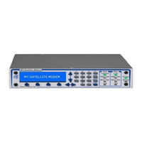
Datum Systems M7 Series Installation And Operation Manual (190 pages)
Brand:
Datum Systems
| Category:
Modem
| Size: 6.01 MB
Table of Contents
Installation and Operation Manual
1
Table of Contents
3
Rohs Compliance
8
About this Manual
9
Revision History
9
Introduction
11
M7 Modem Description
11
Network Types
11
Figure 1-1 - M7 Series Modems
11
Figure 1-2 - Point-To-Point Network
12
Figure 1-3 - Four (4) Site Point-To-Multipoint Network
13
Figure 1-4 - Four (4) Site Mesh Network
13
What's New - this Modem and this Manual
14
Figure 1-5 - M7 Modem (Shown in 1RU Shelf Configuration)
14
Figure 1-6 - M7LT Terminal (Showing Front and Rear Views)
15
M7 Modem Assemblies
16
Figure 1-7 - M7 Modem Assemblies (Shown with Standard Serial Interface)
16
Figure 1-8 - Modem Block Diagram
17
M7 Capabilities
18
Figure 1-9 - Spectrum Analyzer Plot of 0.35 Verses 0.08 Roll-Off Factors
18
Figure 1-10 - Carrier Alpha = 0.08, 1Msps X1.10 Carrier Spacing
19
Table 1-1 - Bandwidth Savings Related to Carrier Alpha
19
Figure 1-11 - Synchronous Serial Interface
20
Figure 1-12 - Ethernet Interface (I7)
21
Figure 1-13 - Express Ethernet Interface (E7)
22
Figure 1-14 - Dual G.703/E1 Interface (G7)
23
Figure 1-15 - HSSI Interface
24
Figure 1-16 - Dual Interface Configuration I7 and S7
24
Figure 1-17 - Dual Interface Configuration I7 and G7
25
Figure 1-18 - Dual Interface Configuration E7 and G7
25
Table 1-2 - Internal Framing Options
26
Forward Error Correction (FEC) Options
28
Table 1-3 - Modulation, FEC, and Code Rates
28
Figure 1-19 - Reed-Solomon Block Diagram
30
Table 1-4 - Reed-Solomon Modes
30
Figure 1-20 - TCP Option Card
31
M7 Series Feature Sets
32
1:1 Redundancy Function (Future Option)
32
Table 1-5 - M7 Series Feature and Option Matrix
32
Installation Requirements
33
Unpacking
33
Mounting Considerations
33
Modem Connections
34
Figure 2-1 - M7 Rear Panel with Synchronous Serial Interface Option
34
Figure 2-2 - M7LT Rear Panel with AC Prime Power Input
34
Figure 2-3 - M7LT Rear Panel with DC Prime Power Input
35
Table 2-1 - Remote IP Control Connector Pinout (J4)
35
Table 2-2 - Remote Control Connector Pinout (J5)
36
Table 2-3 - Alarm Connector Pinout (J6)
36
Figure 2-4 - M7LT Rear Panel Connector Options (N Type or F Type)
37
Figure 2-5 - M7LT Rear Panel Indicators
38
Table 2-4 - Rear Panel BUC and LNB Status Indicator
38
Figure 2-6 - M7LT Internal BUC Power Supply (AC Version Shown)
39
Figure 2-7 - M7LT Internal BUC Power Supply (DC Version)
39
Table 2-5 - BUC Power Supply Options
40
Table 2-6 - Synchronous Serial Data Interface Connector Pinout (J11)
41
Table 2-7 - Serial Interface Overhead Channel - IBS Standard Mux - RS-232 (J10)
42
Table 2-8 - Serial Interface Overhead Channel - IBS Standard Mux - RS-485 (J10)
42
Table 2-9 - Serial Interface Overhead Channel - Advanced/Ibs Custom Mux - RS-232 (J10)
43
Table 2-10 - Serial Interface Overhead Channel - Advanced/Ibs Custom Mux - RS-485 (J10)
44
Figure 2-8 - I7 - IP Interface Rear Panel
45
Table 2-11 - I7 IP Interface Connector Pinout (J12)
45
Table 2-12 - I7 Console Connector Pinout (J13)
45
Figure 2-9 - Express Ethernet Interface (E7)
46
Figure 2-10 - Typical SFP Interface Adapters (Optical and Gbe Shown)
46
Table 2-13 - E7 Gigbit Ethernet Interface Ports 1-4 Connector Pinout (J29-J32)
46
Figure 2-11 - G7 - Dual G.703/E1 Interface Rear Panel
47
Figure 2-12 - RJ45 to BNC Adapter
47
Table 2-14 - Port 1 (J22) & Port 2 (J21) Connector - 120 Ohm Balanced Pinout (Rj48C)
47
Table 2-15 - Overhead Interface - RS-232 (J20)
48
Table 2-16 - Overhead Interface - RS-485 (J20)
48
Figure 2-13 - HSSI Interface Rear Panel
49
Table 2-17 - M7 Overhead Channel - IBS Standard Mux - RS-232 (J25)
50
Table 2-18 - M7 Overhead Channel - IBS Standard Mux - RS-485 (J25)
50
Table 2-19 - M7 Overhead Channel - Advanced/Ibs Custom Mux - RS-232 (J25)
51
Table 2-20 - M7 Overhead Channel - Advanced/Ibs Custom Mux - RS-485 (J25)
52
Adding or Changing the Interface Type
53
Option Turbo Product Codes FEC Option Installation
53
Figure 2-14 - Typical Single Interface Card Layout (Synchronous Serial Interface Shown)
53
Figure 2-15 - FEC Option Card Installation
54
Redundancy Connection (Future Option)
55
Operation
57
Operating Procedures
57
Front Panel
57
Figure 3-1 - M7 Front Panel Controls and Indicators
57
Table 3-1 - Modem LED Indicators
58
Table 3-2 - Modulator LED Indicators
58
Table 3-3 - Demodulator LED Indicators
58
Front Panel Control and Monitor Matrix
59
Web Browser Operation
62
Figure 3-3 - Login Page
62
Figure 3-4 - M7 Web Browser Page Sections
63
Figure 3-5 - Summary Status Page
64
Figure 3-6 - Unit Status Page
65
Figure 3-7 - Unit Reference Page
65
Figure 3-8 - Unit Events Log Page
66
Figure 3-9 - Unit Remote IP Control Interface Pages
67
Figure 3-10 - Unit Remote Serial Control Interface Page
67
Figure 3-11 - Unit HTTP Page
68
Figure 3-12 - Unit Event Page
68
Figure 3-13 - Modulator Status Page
69
Figure 3-14 - Modulator if Page
69
Figure 3-15 - Modulator Data Interface Page
70
Figure 3-16 - Modulator Event Page
70
Figure 3-17 - Demodulator Status Page
71
Figure 3-18 - Demodulator if Page
71
Figure 3-19 - Demodulator Data Interface Page
72
Figure 3-20 - Demodulator Event Page
72
Figure 3-21 - Demodulator Monitor Constellation Page
73
Figure 3-22 - Demodulator Monitor Spectrum Analyzer Page
74
Figure 3-23 - Serial Synchronous Interface Status Page
75
Figure 3-24 - Serial Synchronous Interface I/O Page
76
Figure 3-25 - Serial Synchronous Interface Overhead Mux/Demux Page
76
Figure 3-26 - Serial Synchronous Interface ESC Interface Page
77
Figure 3-27 - Serial Synchronous Interface Test Configuration Page
77
Figure 3-28 - Serial Synchronous Interface Event Page
78
Figure 3-29 - I7 Interface Status Page
79
Figure 3-30 - I7 Interface IP Configuration Page
79
Figure 3-31 - I7 Interface MCC Configuration Page
80
Figure 3-32 - I7 Interface Event Page
80
Figure 3-33 - I7 Interface Statistics Page
81
Figure 3-34 - E7 Interface Status Page
82
Figure 3-35 - E7 Interface Events Page
82
Figure 3-36 - E7 Interface I/O Port Configuration Page
83
Figure 3-37 - E7 Interface Qos Configuration Page
83
Figure 3-38 - E7 Interface Statistics Page
84
Figure 3-39 - Dual G.703 Interface Status Page
85
Figure 3-40 - Dual G.703 Interface Send Mux Page
85
Figure 3-41 - Dual G.703 I/O Port 1 Page (Showing D&I Selections)
86
Figure 3-42 - Dual G.703 Interface Event Page
87
Front Panel Monitor and Control Parameters
88
Table 3-4 - M7 Front Panel Parameter Matrix - Modulator Sheet
88
Table 3-5 - Modem (Unit) Parameter Detail
89
Table 3-6 - Modulator Parameter Detail
97
Table 3-7 - Demodulator Parameter Detail
102
Table 3-8 - Synchronous Interface Parameter Detail
108
Table 3-9 - I7 - IP Interface Parameter Detail
113
Table 3-10 - E7- Express Ethernet Interface Parameter Detail
117
Table 3-11 - G7 - Dual G.703/E1 Interface Parameter Detail
123
Table 3-12 - High Speed Serial Interface (HSSI) Parameter Detail
128
Remote Command Interface Control
134
Modem Configuration
134
Figure 3-43 - Alarm Processing
139
Table 3-13 - ASCII Characters Available for Unit Station ID
140
Data Interface Options - Technical Details
141
Figure 3-44 - Express Ethernet Interface Block Diagram
145
Figure 3-45 - Point-To-Point Satellite Network
147
Figure 3-46 - Point-To-Multipoint Satellite Network
148
Figure 3-47 - Four Site Ptmp Hub and One Remote Site Example
148
Figure 3-48 - Four Site Mesh Network Example
149
Figure 3-49 - Configuration of a Mesh Network Site with a Spare Demodulator
150
Data Interface Clock Options
152
Figure 3-50 - Modulator Clock Source Options
153
Figure 3-51 - Demodulator Clock Source Options
154
3.10. Automatic Uplink Power Control (AUPC) Operation
157
Table 3-14 - AUPC Functions
157
Figure 3-52 - AUPC Remote Enabled Network
158
Figure 3-53 - Hub Modulator with Optional AUPC Demodulator
160
Figure 3-54 - Point-To-Multipoint AUPC Configuration for a Four (4) Site Network
161
3.11. Special Control Mechanisms
165
3.12. Storing and Recalling Configuration
166
3.13. Burst Mode Operation
166
Built-In 1:1 Redundancy Mode Operation (Future Option)
167
Figure 3-55 - M7 Connections for 1:1 Redundancy
167
Maintenance
171
Periodic Maintenance
171
Modem Checkout
171
Table 4-1 - Factory Default Parameters
172
Internal Modem Test Functions
173
Figure 4-1 - Loopback Block Diagram
173
Troubleshooting
176
Updating Modem Firmware
178
Upgrading the Modem Feature Set
182
Figure 4-2 - Unit Feature Page
182
Figure 4-3 - Modulator Feature Page
183
Figure 4-4 - Demodulator Feature Page
183
Figure 4-5 - E7 Interface Feature Page
183
Frequently Asked Questions - FAQ
184
Advertisement
Advertisement
Related Products
Datum Systems M7LT Series
Datum Systems M7D Series
Datum Systems M7L Series
Datum Systems M7DL Series
Datum Systems M7XC
Datum Systems PSM-2100L
Datum Systems PSM-4900L
Datum Systems PSM-500
Datum Systems PSM-500L
Datum Systems PSM-500LT
Datum Systems Categories
Modem
Monitor
Measuring Instruments
More Datum Systems Manuals
Login
Sign In
OR
Sign in with Facebook
Sign in with Google
Upload manual
Upload from disk
Upload from URL