Sign In
Upload
Manuals
Brands
Canon Manuals
Printer
imageRUNNER ADVANCE 8095 Series
Canon imageRUNNER ADVANCE 8095 Series Manuals
Manuals and User Guides for Canon imageRUNNER ADVANCE 8095 Series. We have
1
Canon imageRUNNER ADVANCE 8095 Series manual available for free PDF download: Service Manual
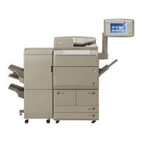
Canon imageRUNNER ADVANCE 8095 Series Service Manual (1386 pages)
Brand:
Canon
| Category:
Printer
| Size: 103.98 MB
Table of Contents
Application
2
Corrections
2
Explanation of Symbols
3
Table of Contents
5
Safety Precautions
21
CDRH Act
21
Laser Safety
21
Handling of Laser System
21
Turn Power Switch
21
Laser Safety
22
CDRH Act
22
Handling of Laser System
22
Turn Power Switch on
23
Safety of Toner
23
Notes before It Works Serving
23
Toner on Clothing or Skin
23
About Toner
23
Points to Note at Cleaning
24
1 Product Overview
25
Product Lineup
25
Main Body
26
Pickup/Delivery System Option
26
Applicable Option for each Model
26
Delivery System Options
27
Pickup System Options
27
Required Options/Conditions
27
Product Lineup
26
Scanning System Options
28
Required Options and Conditions
28
Function Expansion System Options
29
Required Options and Conditions
29
License Products
30
Product Features
31
Service Features
31
Improved Service Operability
31
Easy Access to the Parts at Rear Side
32
Improved Upgrading Operability
32
New Service Mode
32
Applying New Connectors
33
Jam Code
33
Jam/Error Code Display Specifications
33
Service Advantage
33
Product Specifications
34
Power Supply Specifications:
35
Weight and Size
35
Productivity (Print Speed)
36
Paper Type
37
External View/Internal View
48
External Cover
48
Switches, I/F, Others
49
Cross-Section View
49
Operation
50
Power Switch
50
Points to Note on Turning ON/OFF the Power Switch
50
Types of Power Switches
50
Control Panel
51
Main Menu
51
Differences in Main Menu
52
Settings/Registration Menu
52
Differences in Settings/Registration Menu
53
2 Technology
54
Basic Configuration
54
Basic Configuration
55
Functional Configuration
55
Basic Sequence at Power on
56
Basic Sequence at Printing <Condition: A4 1-Sided (2 Sheets), Right Deck, Reverse Delivery
57
Basic Sequence at Printing <Condition: A4 2-Sided (2 Sheets), Right Deck, Reverse Delivery
58
Main Controller
59
Overview
59
Features
59
Hdd
60
Memory
60
Pcbs
60
Specifications/Configuration
60
I/F, Connector
61
Main Controller PCB 1
61
Main Controller PCB 2
61
Function Expansion Options
62
Hdd
63
Boot/Shutdown Sequence
64
Controls
65
Flow of Image Data
65
Security Features (Encryption Key and Certificate, Password Protection)
66
Send
66
Configuration of Security Information
67
TPM Setting for Security Information
67
Preparation before Installing TPM
68
Works before / after Introduction
68
Enable Functionality
69
TPM Key Backup
69
Restore of TPM Key
71
Disable the Feature
72
Environment Settings
72
Function Settings
72
Steps of Data Restoration after Recovery
72
Overview of Actions Taken against Troubles
73
Related Error Code
73
Security Information Storage Location
74
HDD Mirroring Feature (Option)
75
High Capacity HDD (Option)
75
To Start Using this Feature (Installation)
76
HDD Reading/Writing Operation
77
List of Operation Status (LED)
77
Description of Modes
78
Mode Flow at Start-Up
78
Mode Flow During Operation
79
Overview of Trouble Recovery
79
Points to Note in Servicing Concerning Mirroring Functionality
80
Removable HDD (Option)
80
Actions against Troubles – Overview
81
Data Encryption Mechanism
81
HDD Encryption Functionality
81
HDD Encryption/ Mirroring Kit (Optional)
81
E602 and Detailed Codes
82
Points to Note in Initialization Using USB
82
Points to Note in Initialization Via SST
82
Relevant Error Codes
82
E610 and Detailed Codes
83
Service Operations
84
Hdd
84
Main Controller PCB
85
Tpm Pcb
87
Flash PCB
88
Laser Exposure System
89
Overview
89
Parts Configuration
90
Laser on Timing Control
91
Laser ON/OFF Control
91
Overview
91
Details of the Control
92
Main Scanning Synchronization Control
92
Timing of Execution
92
APC (Auto Power Control) Control
93
Laser Beam Intensity Control
93
Sub Scanning Synchronization Control
93
Control Description
94
Duplex Print Magnification Correction
94
Execution Timing
94
Main Scanning Direction
94
Polygon Motor Control
95
Related “Settings/Registration” Mode
95
Laser Shutter Control
96
Consumable Parts
97
Major Adjustments
97
Periodical Servicing List
97
Periodically Replaced Parts
97
When Replacing Parts
97
Image Formation System
98
Overview
98
Charging Specifications
99
Specifications
99
Entire Configuration
100
Process Area
100
Front View
101
Right Side View
101
Toner Supply Area
101
Transfer Area
101
Drive Configuration
102
Waste Toner Feeding Area
102
Print Process
105
Controls
106
Exposure
107
Pre-Exposure Control
107
Primary Charging
108
Primary Charging Bias Control
108
Primary Charging Wire Cleaning Control
108
Primary Charging Shutter Control
109
Shutter Open/Close Operation Sequence
109
Developing
110
Developing Bias Control
110
Developing Supply Shutter Opening/Closing Mechanism
111
Dust-Collection Bias Bontrol
111
Pre-Transfer Charging Bias Control
112
Transfer
112
Pre-Transfer Charging Shutter Control
113
Pre-Transfer Charging Wire Cleaning Control
113
Transfer Bias Control
114
ETB Cleaning Control
115
ETB Engagement/Disengagement Control
115
Separation Control
116
Separation from the Drum
116
Separation from the ETB
117
Drum Cleaning
118
Drum Cleaning Control
118
Separation Claw Reciprocation Control
118
Drum HP Detection
119
Drum-Related Issues
119
Separation Bias Control
119
Drum Heater Control
120
Drum Heater Control
121
Environment Switch: off
121
Environment Switch: on
121
2-Dimensional Shading on
122
Toner Container Detection
123
Toner Level Detection/Toner Supply Control
123
Toner Supply Control
123
Toner Level Detection
124
Waste Toner Feeding Area
125
Waste Toner Full Level Detection
125
Waste Toner Container Detection
126
Waste Toner Feed Screw Lock Detection
126
Image Stabilization Control
127
Potential Control
130
VL Control
131
Determination of Developing Bias
132
Related Error Codes
132
Drum Base Correction
133
LED Light Intensity Correction
133
Operation Description
133
Patch Detection
133
D-Max Control
134
Determination of Contrast Potential (Vcont)
134
Determination of Developing DC (VDC) and Bright Area Potential (VL
134
Determination of Laser Power (Lp)
134
D-Half Control
135
PASCAL Control
135
Auxiliary Control
136
Startup Contrast Potential (Vcont) Correction
136
Initial Rotation APC Contro
137
Laser APC Control
137
Last Rotation APC Control
137
Two Dimension Shading Control
138
Black Band Control
139
White Band Control
139
Low Duty Discharge Control
140
Servicing
141
Consumable Parts
141
Periodical Servicing List
141
Periodically Replaced Parts
141
Primary Charging Assembly
142
Primary Charging Wire
142
When Replacing Parts
142
When the Rear Side Test Print Image Is Dark
143
Pre-Transfer Charging Assembly
144
Pre-Transfer Charging Wire
144
Drum
145
Procedure of Parts Replacement
145
Developing Assembly, Developing Cylinder
146
Drum Side Seals(Front and Rear)
146
Etb
146
Major Adjustments
146
Patch Sensor
146
Trailing Edge Shock Imaget
147
Troubleshooting
147
Uneven Density Correction by 2D Shading
148
Separation Failure Jam Due to Deformation of Separation Claw
151
Uneven Density
152
Developing Assembly
153
Field Remedy
153
Sample Image
153
White Line (Foreign Matter between Developing Sleeves)
153
Smeared Image
155
Fixing
157
Characteristics
157
Whole-Circumference IH Heating Method
157
Overview
157
Parts Configuration
159
Drive Configuration
160
Thermistor, Thermal Switch
160
Fixing Temperature Control
161
Overview
161
High Humidity Environment Startup Mode
162
Low Temperature Environment Startup Mode
162
Normal Startup Mode
162
Temperature Control During Startup
162
Temperature Control During Printing
163
Temperature Control for Standby
163
Energy Saver Mode
164
Low Power Mode
164
Other Temperature Adjustments
164
Down Sequence Control
165
Related Service Mode
165
Heavy Paper
166
Plain Paper
166
When Printing Is Started and the Paper Type Is Switched
166
When the Quality Priority Mode Is Specified
166
Paper Anti-Wrapping Control
167
Thermistor Reciprocating Control
168
Cleaning Web Drive Control
169
Upper Separation Claw Reciprocating Control
169
Cleaning Web Length Detection
170
Detecting an Error Using the Thermal Switch
171
Detecting an Error Using the Thermistor
171
Protective Function
171
Fixing Roller
173
Main Thermistor
173
Sub Thermistor1,2
173
Checking Nip Width
174
Paper Wrinkle
174
Pickup / Feed System
176
Switch/Sensor 1
178
Roller
179
Paper Path
181
Interval Speed
182
Various Types of Control
183
Basic Movement
184
Cassette
184
Deck/Cassette Pickup Unit
184
Deck/Cassette Detection
185
Aper Size Detection
186
Paper Size Detection Switch
187
Paper Level Detection
188
Paper Detection
190
Lifter Control
191
Lifter Error Detection
192
Pickup Retry Control
192
Multi-Purpose Tray Pickup Unit
193
Paper Detection
194
Paper Size Detection
194
Pre-Registration Control
195
Registration Unit
195
Registration Deceleration Control
196
Post-Transfer Guide Attraction Control
197
Registration Acceleration Control
197
Basic Operation
198
Delivery/Reverse Unit
198
Face-Up Delivery
198
Face-Down Delivery
199
Duplex Unit
200
Detection Operation
201
Home Position Operation
201
Side Registration Control
201
Standby Position Operation
201
Circulation Quantity and Limit
202
Less than 314 MM in Size/5 Sheets in Circulation (B5 to A4R)
202
Jam Code List
206
Jam Dection
206
Jam in Feed System
207
Other Jams
207
Forced Paper Feed Control
208
External Auxiliary System
210
Power Supply Configuration
210
Power Supply Configuration Inside the Host Machine
210
Electric Power Management
211
Power Configuration of the Reader Unit
211
Power Supply Control
211
Deep Sleep
212
Energy Saver
212
Energy Saver Function
212
Sleep Standby
212
Distribution of Power and the Switches
213
Environment Control
215
Related Service Modes
215
Airflow
216
Fan Control
216
Location of Fans
216
Counter Control
217
Fan Sequence
217
Explanation of the List
218
Adjusting Rotation of the Upright Control Panel Arm
219
DC Controller PCB
219
Abolition of Supplying MEAP Administrator's CD with Machine
222
Changes
222
Checking the Operating Environment
222
Meap
222
Domain Authentication Management
223
SSO-H Management
223
Local Device Authentication Management
224
Network Ports Used
224
Network Configuration Process
225
Setting up the Network
225
Login by Password Authentication
226
Login to SMS
226
Login by RLS Authentication
227
Initial Display Languages of SMS
228
When Accessing by SMS Installer Service (Password Authentication)
228
Setting for Login by Password Authentication
229
Setting the Method to Login to SMS
229
Setting for Login by RLS Authentication
230
About MEAP Application Management Page
231
Checking MEAP Application Management Page
231
Procedure to Start and Stop a MEAP Application
232
Starting and Stopping a MEAP Application
232
Checking the Platform Information
233
MEAP Specifications
233
The Check Procedure of the Platform Information
233
What Is MEAP Specifications (MEAP Spec Version)?
233
MEAP Spec Version
234
MEAP Spec Version for each Model
234
Checking the System Information of a MEAP Application with SMS
235
MEAP Application System Information
235
Printing the System Information of a MEAP Application
235
Application ID/System Application Name
236
Application Name
236
Application Version
236
Content of MEAP System Information
236
Installing an Application
237
List of Available Resources
237
Procedure to Install Applications
237
Resource
237
Adding a License File
239
Procedure Adding a License File
239
Disabling a License File
240
Procedure Disabling a License File (Suspending a License)
240
Downloading / Removing an Invalidated License File
242
Procedure Downloading / Removing an Invalidated License File
242
Reusable License
243
License for Forwarding
244
Procedure to Create License for Forwarding
244
Procedure to Uninstall an Application
246
Uninstalling an Application
246
About Login Service
247
Login Service
247
Authentication Methods of SSO-H
248
Default Authentication Overview
248
Local Device Authentication
248
SSO-H (Single Sign-On-H) Overview
248
Differences from Conventional SSO
249
Domain Authentication + Local Device Authentication
249
Linkage with Department ID Management When Using SSO-H
249
Access Mode in Sites
250
Site List Acquisition
250
System Manager Linkage
250
Environment Confirmation
251
Logging into Other Domains at Multi-Domain
251
Settings for Access Mode in Sites
251
Changing Login Services
252
Specification of SSO-H
252
SSO/SDL Handling
252
Steps to Change Login Services
252
Initializing the Password
253
Procedure to Initialize the SMS Login Password
253
Backup Items
254
Menu-Related Information
254
Making Backup and Formatting Hard Disk Drive with Service Support Tool
255
Requirements for Backup Using the SST
255
Connecting the Device Using SST
256
Formatting HDD
256
Generating Backup Data to Transfer It to the PC
256
Saving Backup Data
256
Installing Files
257
Procedures to Restore Backup Data
257
Replacing the Hard Disk Drive
257
Restoring Backup File
257
HDD Replacement Procedure
258
MEAP Safe Mode (Level 2)
258
Starting in Safe Mode
258
How to Cancel MEAP SAFE Mode
259
HTTP Server
260
HTTPS Server
260
Port Setup Procedure of HTTP Server
260
Setting HTTP Port for MEAP Application (Level 2)
260
Port Setup Procedure of HTTPS Server
261
Two Types of USB Drivers
263
USB Driver
263
USB Driver Setting (Ir-ADV Series):
263
Using USB Devices
263
Specifications for the Use of USB Keyboards
264
Initialization of MEAP Driver Priority Registration
265
Steps to Initialize Preference Use Registration
265
Steps to Output the USB Device Report Print
265
USB Device Report Print
265
USB Device Information Content
266
Right or Wrong of Report Output
267
The Content of MEAP Preferred Device Information
267
Glossary
268
Reference Material
268
Display Setting of Copy Icon (Level2)
270
Option for Exclusive Individual Measure
270
Embedded RDS
272
Features and Benefits
272
Major Functions
272
Service Call Button
272
Limitations
273
Service Cautions
273
Service Mode Menu Transmission Function
273
Advance Confirmation
274
Advance Preparations
274
Confirmation and Preparation in Advance
274
E-RDS Setup
274
Proxy Settings
276
E-RDS Setting Items
277
E-RDS-Related Setting Items
277
SERVICE BROWSER Setting Items
278
SERVICE CALL BUTTON Setting Items
278
Steps to E-RDS Settings
278
Settings to Display the Service Call Button
281
Steps for Settings of Service Call Completion
281
Steps to Service Call Button Settings
281
Steps for Service Call Settings
282
Steps for Settings of Service Call Cancellation
283
Steps to Service Browser Settings
283
Initializing E-RDS Settings
284
Setting Values and Data to be Initialized
284
Faq
285
How Many Log-Data Can be Stored?
285
In What Case Does a Communication Test with UGW Fail?
285
How Does E-RDS Operate While the Device Is Placed in the Sleep Mode?
286
Is E-RDS Compatible with Section Counter (Department Counter)?
286
Communication Test Results NG! Even if Network Setting Is Set Properly
289
Error Code and Strings
290
Periodic Service
293
Parts Replacement and Clearning
297
List of External / Internal Cover
298
List of Main Unit
300
Periodic Replacing Parts,Durable Parts
306
Periodic Replacing Parts,Durable Parts,Cleaning Parts
306
List of Switch
348
List of PCB
350
Removing Main Controller PCB 1
376
Actions after Parts Replacement
377
Install the Main Controller PCB 1 Unit
377
Remove the Rear Cover
377
Removing Main Controller PCB 2
381
Removing the Laser Scanner Unit
388
Removing the Primary Charging Assembly
392
Removing the Primary Charging Wire Cleaner, Cleaner Holder
393
Replacing the Primary Charging Assembly Grid Wire
396
Removing the Charging Wire
399
Replacing the Primary Charging Wire
399
Installing the Charging Wire
400
Cleaning the Primary Charging Assembly Grid Wire
401
Processing When Replacing the Parts
401
Removing the Pre-Transfer Charging Assembly
402
Removing the Pre-Transfer Charging Wire Cleaner, Cleaner Holder
404
Replacing the Pre-Transfer Charging Wire
406
Cleaning the Pre-Transfer Charging Wire
408
Removing the Process Unit
410
Cleaning the Process Unit
411
Removing the Drum Cleaning Unit
412
Removing the Drum Cleaning Blade
413
Cleaning the Drum Cleaning Unit
415
Replacing the Pre-Exposure Plastic Film
416
Removing the Drum Unit
417
Removing the Photosensitive Drum
418
Processing When Reaplacing the Part
420
Cleaning Photosensitive Drum
421
Cleaning the Drum Edges
422
Removing the Cleaner Separation Claw
423
Removing the Side Seal
423
Removing the Developing Assembly
424
Cleaning the Developing Assembly
427
Removing the ETB Unit
429
Removing the ETB
431
Cleaning the ETB
432
Removing the Transfer Roller
433
Removing the ETB Brush Roller
434
Removing the ETB Cleaning Blade
434
Removing the Waste Toner Container
437
Removing the Drum Heater
438
Removing the Primary Charging Shutter Unit
439
Removing the Pre-Transfer Charging Assembly Shutter Unit
442
Removing the Transfer Cleaning Unit
449
Removing the Post-Transfer Static Eliminator
450
Removing the Toner Receptacle Tray
451
Removing the Hopper Unit
452
Removing the Buffer Unit
456
Removing the Potential Control PCB Unit
459
Removing the Waste Toner Feed Unit
461
Removing the Drum Drive Unit
464
Removing the Developing Drive Unit
466
Removing the Fixing Assembly
469
Cleaning the Inner Delivery Roller
472
Cleaning the Fixing Oil Pan
473
Removing the Fixing Cleaning Web
473
Cleaning the Fixing Roller Static Eliminator
475
Separating the Fixing Upper Unit from the Fixing Lower Unit
476
Removing the Fixing Roller, Insulating Bush and Thrust Stopper
478
Processing after Replacing the Parts
480
Removing the Pressure Roller
480
Removing the Pressure Roller Static Eliminator
481
Removing the Main Thermistor
482
Removing the Sub Thermistor 1
484
Removing the Sub Thermistor 2
485
Cleaning the Upper Separation Claw
486
Removing the Upper Separation Claw
486
Removing the Thermoswitch 2
488
Pickup/Feed System
490
Removing the Left Deck Pickup Roller
490
Removing the Left Pickup Deck
490
Removing the Left Deck Feed Roller
491
Removing the Right Pickup Deck
491
Removing the Right Deck Pickup Roller
492
Cleaning the Right Deck Pickup Sensor 2
493
Removing the Right Deck Feed Roller
493
Removing the Right Deck Separation Roller
493
Removing the Upper Cassette
494
Removing the Upper Cassette Feed Roller
495
Removing the Upper Cassette Pickup Roller
495
Cleaning the Cassette 3 Pickup Sensor 2
496
Removing the Upper Cassette Separation Roller
496
Removing the Lower Cassette
497
Removing the Lower Cassette Pickup Roller
497
Cleaning the Cassette 4 Pickup Sensor 1 (PS22)
498
Removing the Lower Cassette Feed Roller
498
Removing the Lower Cassette Separation Roller
498
Removing the Multi-Purpose Tray Feed Roller
499
Removing the Multi-Purpose Tray Separation Roller
501
Cleaning the Pickup and Fixing Feed Assembly
502
Cleaning the Vertical Path Assembly
502
Cleaning the Fixing Feed Assembly
505
Removing the Left Deck Pickup Unit
511
Removing the Right Deck Pickup Unit
512
Removing the Cassettes 3 and 4 Pickup Unit
513
Removing the Vertical Path Cassette Pickup Drive Unit
514
Removing the Registration Unit
517
Removing the Left Deck Pickup Drive Unit
520
Removing the Main Drive Unit
521
Removing the Filter (for Primary Charging)
526
Removing the Ozone Filter
526
Removing the DC Controller PCB
527
Removing the Power Supply Assembly
530
Removing the Fixing Power Unit
531
Removing the Feed Driver PCB
532
Removing the Upper High Voltage Unit
533
Removing the Upright Control Panel
534
Adjustment
536
Before Replacing
540
When Replacing
540
Flash PCB
541
Tpm Pcb
541
Photosensitive Drum
544
Remove the Drum EEROM
544
Developing Assembly
545
Drum Side Seals (Front and Rear)
545
ETB Unit / ETB
546
Fixing System
546
Waste Toner Container
546
Test Print
549
17 Gradations (TYPE=2/3)
550
Grid (TYPE=1)
550
How to View the Test Print
550
Halftone (TYPE=5/6/11/12/13/14)
551
Solid White (TYPE=4)
551
Horizontal Line (TYPE=8/9/10)
552
Solid Black (TYPE=7)
552
Image Faults
553
ADF Black Line
558
Bleed-Thru/Soil Appeared on the Back of the Paper
559
Uneven Density
569
Adjustment Procedure
573
MTF Adjustment
573
When Disabling the MTF Adjustment
574
When Making Fine Adjustment after Sampling the MTF Value
574
Feed Faults
575
Downloading System Software
580
Overview of Version Upgrade
580
Version Upgrade
580
Normal Mode(Recommend)
581
Safe Mode
581
Writing System Software
581
System Software Components
582
Note on Download Process
583
Version Upgrade Via SST
583
Copying System Software
584
Downloading the System Software
584
Connection
586
Downloading System Software (Assist Mode)
587
Downloading System Software (Single Mode)
589
When Executing Format ALL Startup in Normal Mode
592
Steps of Formatting
593
Mounting New HDD
595
Backup
596
Steps to Upload Data
596
Steps to Download Data
598
Relation between Sst and Usb Memory Storage Device
599
Version Upgrade Using USB Memory Storage Device
599
System CD to SST
600
Requirements for USB Memory Storage Device
601
SST to USB Memory Storage Device
601
Menu/Function Overview
604
Upgrading System Software
604
Points to Note When Operating/Using System Software
605
Downloading/Writing System Software (Automatic)
606
Downloading System Software (Confirmation)
607
Downloading System Software (Overwriting)
609
Clearing Download File
612
Other Menu
612
Error Code: E753-0001
613
Upgrading by SST
613
List of Initial Check Items
614
Error Code
615
Location Code
616
Points to Note When Clearing HDD
616
Points to Note When Clearing MN-CON
616
E000 to E069
617
Error Code Details
617
E100 to E197
627
E202 to E280
631
E301 to E355
634
E400 to E490
636
E500 to E5F9
638
E602
655
E604 to E677
688
E710 to E753
689
E804 to E996
694
Jam Type
697
Main Unit
698
Duplex Color Image Reader-C1
700
Paper Deck Unit-C1
701
POD Deck Light-A1
701
Inserter-K1
702
Professional Puncher-C1/Integration Unit-B1
703
Paperfolding Unit-H1
705
Staple Finisher-D1/Booklet Finisher-D1
706
Alarm Code
707
List of Alarm Code
707
Service Mode
716
Service Mode Item Explanations
717
Service Mode Menu
717
Display of Error Code/Alarm Code Description
718
I/O Information Enhancement
718
COPIER > OPTION > BODY, Item Segmentation
719
Switching Screen
720
Back-Up of Service Mode
721
Language Switch
721
Copier
722
Acc-Sts
744
User
744
Analog
746
Cst-Sts
747
Hv-Sts
748
CCD
749
Dpot
752
Dens
753
Sensor
754
Environment Indication
755
Envrnt
755
Misc
755
2D-Shade
756
Host Machine_Dc Controller (DC-CON>P001 to P030)
757
I/O (I/O Display Mode)
757
Host Machine_Main Controller (DC-CON>P001 to P005))
766
Reader (R-CON>P001 to P005)
766
ADF (FEEDER>P001 to P007)
767
Paper Deck Unit - C1 (DC-CON>P048 to P050)
768
POD Deck Lite - A1 (DC-CON>P047 to P050)
769
Inserter - K1 (DC-CON>P045 to P054)
770
Paper Folding Unit - H1 (DC-CON>P045 to P071)
772
Professional Puncher - C1 + Integration Unit-B1
775
Staple Finisher - D1 / Booklet Finisher -D1
775
Inner Trimmer - A1 (SORTER>P024 to P028)
790
Adj-Xy
792
Adjust
792
Ae
792
Img-Reg
804
Laser
804
Develop
805
Blank
807
V-Cont
808
Hv-Pri
809
Pascal
809
Hv-Tr
810
Feed-Adj
817
Sens-Adj
841
Fnc-Sw
845
Dsply-Sw
852
Sorter
938
T-Cntr
938
Display
944
Feeder
944
Soater
949
Board
962
Installation
963
Checking before Installation
964
Checking Power Supply
964
Checking the Installation Environment
964
Points to Note at Installation Work
965
Table of Options Combination
965
Order to Install the Host Machine and the Options
966
Checking the Contents
967
Unpacking
971
Installation of the Upright Control Panel
973
Installing the Pickup Assembly
982
Installing the Fixing Assembly
983
Installing the Toner Container
985
Installing the Exhaust Filter
986
Installing the USB Device Port
987
Setting the Environment Heater Switch
990
Turning off the Main Power
990
Turning on the Main Power
990
Installation of the Host Machine
991
Other Installation Work
991
Toner Stirring
991
Setting the Deck
992
Setting the Paper Cassette
994
Auto Adjust Gradation
995
Image Position Adjustment
995
Left Edge Margin Adjustment (1St Side)
995
Adjusting Margin of Multi-Purpose Pickup Tray
997
Left Edge Margin Adjustment (2Nd Side)
998
Leading Edge Margin Adjustment (1St Side)
999
Leading Edge Margin Adjustment (2Nd Side)
999
Checking by the Remote Host Address
1000
Checking the Network Connection
1000
Operation Procedure Using Ping
1000
Checking Network Function on the Main Controller
1001
Checking the Network Setting of the Host Machine
1001
Network Troubleshooting
1001
When Relocating the Machine
1002
Printer Cover -B1
1005
Check Items When Turning off the Main Power
1006
Installation Procedure
1006
Checking the Contents (ASIA Only)
1010
Checking the Parts to be Installed (Europe Only)
1010
Reader Heater Unit
1010
Reader Heater Unit-G1
1010
Cassette Heater Unit
1016
Paper Deck Heater Unit-A1
1020
Installation Procedure (Paper Deck Unit-C1)
1021
Utility Tray-A1
1029
When Installing the USB Keyboard
1031
Card Reader-C1
1032
Contents of Card Reader-C1
1032
Contents of Copy Card Reader Attachment-A2
1033
Voice Guidance Kit-F1
1040
Points to Note at Installation
1046
Expansion Bus-F1/F2
1047
Ipsec Board-B2
1047
Wireless LAN Board-B1
1048
Removing the Main Controller PCB 1
1050
Installing the Expansion Bus-F1 and the Ipsec Board-B2 Simultaneously
1051
Additional Memory Type B (512MB)
1058
Combination of HDD Options
1060
[TYPE-1] Option HDD (250GB)
1061
List of Data to be Deleted
1062
Points to Note Regarding Data Backup/Export
1062
List of Data to be Backed up
1063
Making a Backup of the Data (Reference Only)
1063
Backup of MEAP Application
1064
Paper Information Export Procedure
1064
Printer Settings Export Procedure
1064
Settings/Registration Export Procedure
1064
Backup of User Inbox and Advanced Box Document Data
1065
User Authentication Information Registered by SSO-H
1065
Backup Method of User Inbox and Advanced Box Document Data
1066
Quick Menu Information Export Procedure
1066
Restoring the Backup Data of User Inbox and Advanced Box Document Data
1066
User Information of the Advanced Box Export Procedure
1066
Assembling the Option HDD
1067
Procedure to Replace with the HDD
1068
Execution of Auto Gradation Adjustment
1070
Installing the System Software Using the SST
1070
[TYPE-2] Removable HDD Kit
1071
Removing the HDD and HDD Case Unit
1072
Disassembling and Assembling of the HDD Removed from Host Machine
1075
[TYPE-3] Option HDD (250GB) + Removable HDD Kit
1082
Removable HDD Kit
1083
Points to Note When Unpacking HDD Data Encryption & Mirroring Kit
1100
HDD Mirroring Kit or HDD Data Encryption & Mirroring Kit
1101
After Installing HDD Data Encryption & Mirroring Kit
1140
Checking the Security Mark
1140
Checking the Security Version
1140
Setting for Mirroring
1141
[TYPE-6] HDD Data Encryption & Mirroring Kit
1142
Special Tools
1309
Display Settings
1349
Paper Settings
1349
External Interface
1357
Adjust Action *1
1358
Maintenance
1358
Common
1359
Function Settings
1359
10-Lv
1362
Copy *1
1362
Printer
1362
Send
1363
Receive/Forward
1364
Store/Access Files
1365
Encrypted Secure Print
1366
Set Destination
1367
Device Management
1368
Management Settings
1368
User Management
1368
License/Other
1370
Data Management
1371
Backup Data
1372
Advertisement
Advertisement
Related Products
Canon imageRUNNER 2535i
Canon imageRUNNER 2545i
Canon imageRUNNER 2520
Canon imageRUNNER ADVANCE-series
Canon imageRUNNER 2002
Canon Imagerunner 3235
Canon imageRUNNER
Canon imageRUNNER 3245 Series
Canon imageRUNNER 1019j
Canon imageRUNNER 1023n
Canon Categories
Printer
Digital Camera
All in One Printer
Camcorder
Scanner
More Canon Manuals
Login
Sign In
OR
Sign in with Facebook
Sign in with Google
Upload manual
Upload from disk
Upload from URL