Sign In
Upload
Manuals
Brands
Brother Manuals
Sewing Machine
RH-9820
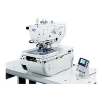
Brother RH-9820 Manuals
Manuals and User Guides for Brother RH-9820. We have
9
Brother RH-9820 manuals available for free PDF download: Service Manual, Manual Del Instrucción, Instruction Manual, Parts Book, Catalog, Brochure & Specs, Brochure
Brother RH-9820 Service Manual (237 pages)
ELECTRONIC EYELET BUTTON HOLER
Brand:
Brother
| Category:
Sewing Machine
| Size: 5.8 MB
Table of Contents
Safety Instructions
3
Maintenance and Inspection
5
Machine Specifications
10
Function Settings
11
List of Advanced Functions
12
Memory Switch Setting Method (Advanced)
13
List of Memory Switch Settings
14
Error History Checking Method
23
Input Checking Method
24
Output Checking Method
27
Software Version Checking Method
30
Reading/Writing Data
31
Data Read/Write Mode
32
Reading Parameter Data from the CF Card
33
Writing Error Log Data to the CF Card
34
Mechanical Descriptions
35
Zigzag and Thread Take-Up Mechanisms
36
Needle Bar Rocking Mechanism
37
Feed Mechanism
38
Presser Foot Mechanism
39
Cloth Opening Mechanism
40
Cutter Mechanism
41
Spreader Mechanism
42
Upper Tension Release Mechanism
43
Lower Thread Release and Lower Thread Take-Up Mechanisms
44
Lower Thread Trimmer Mechanism
45
Disassembly
47
Covers and Presser Foot Mechanism
48
Upper Shaft Motor Unit Mechanism
49
Feed Mechanism
50
X Feed Unit
51
Lower Thread Tension Mechanism
52
Spreader Mechanism
53
Looper Mechanism
54
Needle Bar Rocking Mechanism
55
Looper Base Mechanism
56
Needle Bar Mechanism
57
Lubrication
58
Zigzag and Thread Take-Up Mechanisms
60
Upper Shaft Mechanism
61
Cutter Mechanism
62
Assembly
63
Cutter Mechanism
64
Needle Bar Mechanism (1)
66
Zigzag Mechanism
68
Upper Shaft Mechanism
70
Thread Take-Up Mechanism
73
Needle Bar Mechanism (2)
74
Y Feed Mechanism
78
Looper Base Mechanism
82
Needle Bar Rocking Mechanism
88
Lower Shaft Mechanism
94
Looper Mechanism
99
Spreader Mechanism
101
Upper Thread Trimmer Mechanism
103
Threading Mechanism
104
Feed Base Mechanism
106
X Feed Shaft Holder
113
X Feed Mechanism
116
Lower Thread Tension Mechanism
118
Upper Shaft Motor Mechanism
120
Covers
124
Work Clamp Plate Mechanism
126
Lower Thread Trimming Mechanism
130
Specifications
134
Routing the Harnesses
138
Routing the Air Tubes
140
Solenoid Valve Tubes and Functions
142
Lubrication and Greasing and Routing the Oil Tubes
144
Adjustments
150
Adjusting the Zigzag Width (Stitch Width)
151
Adjusting the Zigzag Base Line Position
152
Adjusting the Needle and Looper Timing
155
Adjusting the Looper Stroke
156
Adjusting the Height of the Needle Bar
157
Adjusting the Clearance between the Loopers and Needle
158
Adjusting the Spreader Installation Positions
159
Adjusting the Spreader Timing
160
Adjusting the Height of the Throat Plate
161
Changing the Cutting Length (Replacing the Hammer)
162
Adjusting the Cutting Surface of the Hammer
163
Adjusting the Contact between the Knife and the Hammer
164
Making the Cutter Driving Shaft and Driving Shaft Presser Move Together
165
Replacing the Knife and Adjusting Its Position
166
Making Fine Adjustments to the Knife Position
167
Adjusting the Cutting Pressure
169
Adjusting the Work Clamp Lift Amounts
170
Adjusting the Work Clamp Positions
171
Adjusting the Positions of the Work Clamp Plates
172
Adjusting the Cloth Opening Amounts
173
Adjusting the Upper Thread Feeding Amount
174
Replacing and Adjusting the Upper Movable Knife
175
Adjusting the Upper Movable Knife
176
Adjusting the Position of the Thread Trimmer Lever Bracket
177
Replacing the Movable Knife and Fixed Knife
178
Adjusting the Cutting Pressure
179
Adjusting the Thread Nipper Assembly and Opener
180
Adjusting the Thread Handler
182
Replacing the Movable Knife and Fixed Knife
183
Adjusting the Movable Knife Installation Position
184
Adjusting the Position of the Sub Clamp
185
Differences from Older Models
186
Adjustment of the Phase for the Take-Up Roller Cam
190
Adjusting the Needle Bar and Looper Base Turning Center
191
Adjusting the Upper Thread Loosening Amount
192
Adjusting the Lower Thread Loosening Amount
193
Adjusting the Looper Base Home Position
194
Adjusting the Feed Base X Home Position and y Home Position
196
Adjusting the Needle up Signal Home Position for the Upper Shaft and Upper Shaft Motor
198
Adjusting the Upper Shaft Stop Position
200
Installing (Replacing) the Sub Clamp on the Left Side
201
Electrical Mechanism
206
Inside the Control Box and Operation Panel Structure
207
Description of Fuses
208
Description of Connectors
209
Symptoms When There Are Poor Connections
212
Troubleshooting
215
Diagnosis Flowchart
216
Remedy
219
Error Codes
228
Troubleshooting
234
Advertisement
Brother RH-9820 Instruction Manual (134 pages)
Electronic eyelet button holer
Brand:
Brother
| Category:
Sewing Machine
| Size: 2.34 MB
Table of Contents
Safety Instructions
3
Maintenance and Inspection
5
Table of Contents
8
1 Names of Major Parts
10
2 Machine Specifications
11
Specifications
11
Sewing Shapes
12
3 Installation
13
Table Processing Diagram
13
When Setting up on Top of the Table
14
When Embedding into the Table
15
Installing the Control Box
16
Installing the Table Reinforcement Plates (Embedded Installation Only)
17
Installing the Machine Head
17
When Setting up on Top of the Table
17
When Embedding into the Table
19
Tilting Back and Returning the Machine Head
20
Installing the Belt Cover and Feed Bar Cover U
21
Installing the Oiler
21
Installing the Operation Panel
22
Installing the Cotton Stand
22
Installing the Air Unit and Valve Unit
23
Installing the 2-Pedal Foot Switch (When Using the 2-Pedal Foot Switch)
23
Installing the Treadle Unit (When Using the Treadle)
24
When Setting up on Top of the Table
24
When Embedding into the Table
24
Installing the Hand Start Switch (When Using the Hand Start Switch)
25
Connecting the Cords
27
Connecting the Connectors Inside the Control Box
27
Connecting the Ground Wire
31
Connecting the Power Cord
32
Connecting the Air Tubes
33
Securing the Cords
33
Installing the Air Hose
34
Adjusting the Air Pressure
34
Installing the Eye Guard
35
Installing the Dust Bag
35
Installing and Removing the Work Clamp Plates
36
Lubrication
37
Adding Oil
37
Lubrication
38
4 Preparation before Sewing
39
Installing the Needle
39
Threading the Upper Thread
40
Threading the Lower Thread
41
Threading the Gimp
42
Threading the Threads When the Cotton Stand Is Installed on the Right Side
43
Setting the Material
44
5 Using the Sewing Machine
45
Operation)
45
Name and Function of each Operation Panel Item
45
Starting the Sewing Machine
47
Program Setting Method
48
Parameter List
50
Checking the Sewing Pattern in Test Mode
55
Switching Cutting Operation
57
Changing the Material Setting Position
58
Using Threading Mode
59
6 Using the Sewing Machine (Sewing Operation)
60
Automatic Sewing (Automatic Mode)
60
Using the STOP Switch
61
Pausing Sewing During Automatic Sewing
61
Canceling Manual Sewing or Test Feeding
63
Adjusting the Thread Tension
64
7 Using the Sewing Machine (Operation Panel: Advanced Operation)
66
Using Cycle Programs
66
Setting Memory Switches
69
List of Memory Switch Settings
70
Resetting the Data (Initialization)
71
Changing the Production Counter Setting
72
Displaying the Help Screen
73
Manual Sewing (Manual Mode)
74
Switching the Sewing Mode While Sewing Is in Progress
76
8 Cleaning and Inspection
77
Daily Cleaning and Inspection
77
Cleaning
77
Checking the Air Filter
78
Checking the Needle
78
Monthly Cleaning and Inspection
78
Cleaning the Control Box Air Inlet Port
78
Cleaning and Inspection as Required
79
Draining Lubricating Oil
79
Cleaning the Eye Guard
79
Lubrication
79
Draining Water
79
9 Standard Adjustments
80
Adjusting the Heights of the Spreaders and Loopers
80
Adjusting the Zigzag Width (Stitch Width)
81
Adjusting the Zigzag Base Line Position
82
Adjusting the Needle and Looper Timing
85
Adjusting the Looper Stroke
86
Adjusting the Height of the Needle Bar
87
Adjusting the Clearance between the Loopers and Needle
88
Adjusting the Needle Guard
88
Adjusting the Spreader Installation Positions
89
Adjusting the Spreader Timing
90
Adjusting the Height of the Throat Plate
91
Changing the Cutting Length (Replacing the Hammer)
92
Adjusting the Cutting Surface of the Hammer
93
Filing the Cutting Surface of the Hammer
93
Adjusting the Contact between the Knife and the Hammer
94
Adjusting the Axial Play of the Hammer
94
Making the Cutter Driving Shaft and Driving Shaft Presser Move Together
95
Replacing the Knife and Adjusting Its Position
96
Replacing the Knife
96
Making Fine Adjustments to the Knife Position
97
Adjusting the Cutting Pressure
99
Adjusting the Work Clamp Lift Amounts
100
Adjusting the Work Clamp Positions
101
Adjusting the Positions of the Work Clamp Plates
102
Adjusting the Cloth Opening Amounts
103
Adjusting the Upper Thread Feeding Amount
104
Adjusting the Lower Thread Feeding Amount <-01 Specifications Only
105
Replacing and Adjusting the Upper Movable Knife
105
Replacing the Upper Movable Knife
105
Adjusting the Upper Movable Knife
106
Adjusting the Position of the Thread Trimmer Lever Bracket
107
Replacing and Adjusting the Movable Knife and Fixed Knife (for the Lower Thread and Gimp) <-01 Specifications
108
Replacing the Movable Knife and Fixed Knife
108
Adjusting the Cutting Pressure
109
Adjusting the Meshing Amount
109
Adjusting the Thread Nipper Assembly and Opener
110
Adjusting the Thread Handler
112
Replacing and Adjusting the Movable Knife and Fixed Knife (for the Lower Thread and Gimp) <-02 Specifications
113
Replacing the Movable Knife and Fixed Knife
113
Adjusting the Cutting Pressure
113
Adjusting the Movable Knife Installation Position
114
Adjusting the Position of the Auxiliary Clamp
115
Adjusting the Gimp Trailing Length <-02 Specifications Only
116
Adjusting the Position of the Lower Thread Presser <-02 Specifications Only
117
Installing (Replacing) the Auxiliary Clamp on the Left Side
118
Adjusting the Throttle Valves
123
Adjusting the Throttle Valve of the Cutter Valve
123
Adjusting the Throttle Vales of the Solenoid Valves
124
10 Sewing Circular Stitches
125
11 Error Codes
126
12 Troubleshooting
131
Instruction Manual
134
Brother RH-9820 Instruction Manual (125 pages)
ELECTRONIC EYELET BUTTON HOLER
Brand:
Brother
| Category:
Sewing Machine
| Size: 3.04 MB
Table of Contents
Safety Instructions
3
Maintenance and Inspection
5
Table of Contents
8
1 Names of Major Parts
10
2 Machine Specifications
11
Specifications
11
Sewing Shapes
12
3 Installation
13
Table Processing Diagram
13
When Setting up on Top of the Table
14
When Embedding into the Table
15
Installing the Control Box
16
Installing the Table Reinforcement Plates (Embedded Installation Only)
17
Installing the Machine Head
17
When Setting up on Top of the Table
17
When Embedding into the Table
19
Tilting Back and Returning the Machine Head
20
Installing the Belt Cover and Feed Bar Cover U
21
Installing the Oiler
21
Installing the Operation Panel
22
Installing the Cotton Stand
22
Installing the Air Unit and Valve Unit
23
Installing the 2-Pedal Foot Switch (When Using the 2-Pedal Foot Switch)
23
Installing the Treadle Unit (When Using the Treadle)
24
When Setting up on Top of the Table
24
When Embedding into the Table
24
Installing the Hand Start Switch (When Using the Hand Start Switch)
25
Connecting the Cords
27
Connecting the Connectors Inside the Control Box
27
Connecting the Ground Wire
31
Connecting the Power Cord
32
Connecting the Air Tubes
33
Securing the Cords
33
Installing the Air Hose
34
Adjusting the Air Pressure
34
Installing the Eye Guard
35
Setting the Scrap Holder for the Knife
35
Installing and Removing the Work Clamp Plates
36
Lubrication
37
Adding Oil
37
Lubrication
38
4 Preparation before Sewing
39
Installing the Needle
39
Threading the Upper Thread
40
Threading the Lower Thread
41
Threading the Gimp
42
Threading the Threads When the Cotton Stand Is Installed on the Right Side
43
Setting the Material
44
5 Using the Sewing Machine (Operation Panel: Basic Operation)
45
Name and Function of each Operation Panel Item
45
Starting the Sewing Machine
47
Program Setting Method
48
Parameter List
50
Checking the Sewing Pattern in Test Mode
55
Switching Cutting Operation
57
Changing the Material Setting Position
58
Using Threading Mode
59
6 Using the Sewing Machine (Sewing Operation)
60
Automatic Sewing (Automatic Mode)
60
Using the STOP Switch
61
Pausing Sewing During Automatic Sewing
61
Canceling Manual Sewing or Test Feeding
63
Adjusting the Thread Tension
64
7 Using the Sewing Machine (Operation Panel: Advanced Operation)
66
Using Cycle Programs
66
Setting Memory Switches
69
List of Memory Switch Settings
70
Resetting the Data (Initialization)
71
Changing the Production Counter Setting
72
Displaying the Help Screen
73
Manual Sewing (Manual Mode)
74
Switching the Sewing Mode While Sewing Is in Progress
76
8 Cleaning and Inspection
77
Daily Cleaning and Inspection
77
Cleaning
77
Checking the Air Filter
78
Checking the Needle
78
Monthly Cleaning and Inspection
78
Cleaning the Control Box Air Inlet Port
78
Cleaning and Inspection as Required
79
Draining Lubricating Oil
79
Cleaning the Eye Guard
79
Lubrication
79
Draining Water
79
9 Standard Adjustments
80
Adjusting the Heights of the Spreaders and Loopers
80
Adjusting the Zigzag Width (Stitch Width)
81
Adjusting the Zigzag Base Line Position
82
Adjusting the Needle and Looper Timing
85
Adjusting the Looper Stroke
86
Adjusting the Height of the Needle Bar
87
Adjusting the Clearance between the Loopers and Needle
88
Adjusting the Needle Guard
88
Adjusting the Spreader Installation Positions
89
Adjusting the Spreader Timing
90
Adjusting the Height of the Throat Plate
91
Changing the Cutting Length (Replacing the Hammer)
92
Adjusting the Cutting Surface of the Hammer
93
Filing the Cutting Surface of the Hammer
93
Adjusting the Contact between the Knife and the Hammer
94
Adjusting the Axial Play of the Hammer
94
Making the Cutter Driving Shaft and Driving Shaft Presser Move Together
95
Replacing the Knife and Adjusting Its Position
96
Replacing the Knife
96
Making Fine Adjustments to the Knife Position
97
Adjusting the Cutting Pressure
99
Adjusting the Work Clamp Lift Amounts
100
Adjusting the Work Clamp Positions
101
Adjusting the Positions of the Work Clamp Plates
102
Adjusting the Cloth Opening Amounts
103
Adjusting the Upper Thread Feeding Amount
104
Adjusting the Lower Thread Feeding Amount <-01 Specifications Only
105
Replacing and Adjusting the Upper Movable Knife
105
Replacing the Upper Movable Knife
105
Adjusting the Upper Movable Knife
106
Adjusting the Position of the Thread Trimmer Lever Bracket
107
Replacing and Adjusting the Movable Knife and Fixed Knife (for the Lower Thread and Gimp) <-01 Specifications
108
Replacing the Movable Knife and Fixed Knife
108
Adjusting the Cutting Pressure
109
Adjusting the Meshing Amount
109
Adjusting the Thread Nipper Assembly and Opener
110
Adjusting the Thread Handler
112
Replacing and Adjusting the Movable Knife and Fixed Knife (for the Lower Thread and Gimp) <-02 Specifications
113
Replacing the Movable Knife and Fixed Knife
113
Adjusting the Cutting Pressure
113
Adjusting the Movable Knife Installation Position
114
Adjusting the Position of the Sub Clamp
115
Adjusting the Gimp Trailing Length <-02 Specifications Only
116
Adjusting the Position of the Lower Thread Presser <-02 Specifications Only
117
10 Error Codes
118
11 Troubleshooting
123
Instruction Manual
125
Advertisement
Brother RH-9820 Parts Book (132 pages)
ELECTRONIC EYELET BUTTON HOLER
Brand:
Brother
| Category:
Sewing Machine
| Size: 12.71 MB
Table of Contents
Table of Contents
5
Machine Body
7
Needle Bar and Thread Take-Up Mechanism
11
Upper Shaft Mechanism
13
Zigzag Mechanism
15
Needle Bar Rocking Mechanism
17
F1. Work Clamp Mechanism
19
F2. Work Clamp Mechanism
23
F3. Work Clamp Mechanism
25
Feed Mechanism
27
Cutter Mechanism
31
Lower Shaft Mechanism
33
Looper Mechanism
35
Double Chain Stitch Looper Mechanism
37
Spreader Mechanism
41
Lubrication
43
P1. Threading Mechanism
47
P2. Threading Mechanism
51
P3. Threading Mechanism
53
Q1. Thread Trimmer Mechanism
55
Q2. Thread Trimmer Mechanism
57
Upper Thread Trimmer Mechanism
59
S1. Control Box Mechanism
61
Power Switch Mechanism
65
U1. Air Pressure Mechanism
67
U2. Air Pressure Mechanism
69
Power Supply Equipment Mechanism
71
Operation Panel Mechanism
73
Motor Mechanism
75
Foot Switch Pedal Mechanism
77
AA1. Attachment Set
79
AA2. Attachment Set
85
AA3. Attachment Set
87
AA4. Attachment Set
89
AA5. Attachment Set
95
AA6. Attachment Set
99
AB. Upper Thread Breakage Detector
101
AC. Air Pressure Detector
101
AD. Upper Thread Nipper Device Set
103
AE. Cut Length Changeover Device
107
AF. Fly Indexer
111
Accessories
115
Sp. Different Parts List
119
Wa. Warning Labels
122
Index
123
Brother RH-9820 Instruction Manual (12 pages)
AIR PRESSURE DETECTOR
Brand:
Brother
| Category:
Security Sensors
| Size: 0.57 MB
Table of Contents
Contents
2
Table of Contents
2
機能
3
Functions
3
取り付け方
4
Installation
4
エアー圧力検出装置の取り付け方
5
Installing the Air Pressure Detector
5
エアー圧力設定の仕方
6
Setting the Air Pressure
6
ハーネスの接続
7
Connecting the Harness
7
設定の仕方
10
Setting Method
10
パーツリスト
11
Parts List
11
目 录
3
功能
3
Funciones
3
安装方法
4
Instalación
4
安装气压检出装置
5
Instalación del Detector de Presión de Aire
5
设置气压
6
Ajuste de la Presión de Aire
6
电线的接续
7
Conexión de Los Mazos de Conductores
7
设定方法
10
Método de Ajuste
10
零部件清单
11
Lista de Partes
11
Brother RH-9820 Catalog (13 pages)
Industrial Sewing Machines
Brand:
Brother
| Category:
Sewing Machine
| Size: 1.62 MB
Table of Contents
Lock Stitch Sewing Machine
4
Twin Needle Lock Stitch Sewing Machine
6
Twin Needle Split Needle Bar Lock Stitch Sewing Machine
7
Buttonhole Sewing Machine
8
Button Attaching Machine
8
Bar Tacking Machine
9
Pattern Tacking Machine
9
Programmable Electronic Pattern Sewing Machine
10
Double Chain Stitch Sewing Machine
11
Brother RH-9820 Brochure & Specs (6 pages)
Buttonhole Electronic Eyelet Button Hole Specifications Sheet
Brand:
Brother
| Category:
Sewing Machine
| Size: 0.86 MB
Brother RH-9820 Brochure (6 pages)
Electronic eyelet button holer
Brand:
Brother
| Category:
Sewing Machine
| Size: 0.94 MB
(Spanish) Brother RH-9820 Manual Del Instrucción (134 pages)
Instruction Manual - Spanish
Brand:
Brother
| Category:
Sewing Machine
| Size: 5.25 MB
Table of Contents
Instrucciones de Seguridad
3
Table of Contents
8
1 Nombres de las Piezas Principales
10
2 Especificaciones de la Máquina
11
Especificacion
11
Formas de Costura
12
3 Instalación
13
Diagrama de Procesado para Mesa
13
Al Instalarla Encima de la Mesa
14
Al Instalarla Incrustada en la Mesa
15
Instalación de la Caja de Control
16
Instalación de las Placas de Refuerzo de la Mesa (sólo Instalación Incrustada)
17
Instalación de la Cabeza de la Máquina
17
Al Instalarla Encima de la Mesa
17
Al Instalarla Incrustada en la Mesa
19
Inclinación Hacia atrás y Volver a la Posición Original la Cabeza de la Máquina
20
Instalación de la Cubierta de Correa y Cubierta en U de Barra de Alimentación
21
Instalación del Lubricador
21
Instalación del Panel de Control
22
Instalación del Soporte de Hilo
22
Instalación de la Unidad Neumática y la Unidad de Válvula
23
Instalación del Interruptor de 2 Pedales (cuando Use el Interruptor de 2 Pedales)
23
Instalación del Pedal (cuando Se Usa el Pedal)
24
Al Instalarla Encima de la Mesa
24
Al Instalarla Incrustada en la Mesa
24
Instalación del Interruptor de Arranque de Mano (cuando Se Usa el Interruptor de Arranque de Mano)
25
Conexión de Los Cables
27
Conexión de Los Conectores en el Interior de la Caja de Controles
27
Conexión del Cable a Tierra
31
Conexión del Cable de Alimentación
32
Conexión de Los Tubos de Aire
33
Asegurando Los Cables
33
Instalación de la Manguera de Aire
34
Ajuste de la Presión de Aire
34
Instalación del Protector de Ojos
35
Instalación de Bolsa de Polvo
35
Instalación y Desmontaje de las Placas de Prensatelas
36
Lubricación
37
Agregando Aceite
37
Lubricación
38
4 Preparativos Antes de Coser
39
Instalación de la Aguja
39
Enhebrado del Hilo Superior
40
Devanado del Hilo Inferior
41
Enhebrado del Hilo del Cordoncillo
42
Enhebrando Los Hilos cuando el Soporte de Hilo Está Instalado del Lado Derecho
43
Colocación del Material
44
5 Usando la Maquina de Coser (Panel de Control: Operaciones Basicas)
45
Nombre y Función de cada Elemento del Panel de Operación
45
Usando la Máquina de Coser
47
Método de Ajuste de Programa
48
Lista de Parámetros
50
Verificación del Patrón de Costura en el Modo de Prueba
55
Cambio de Operación de Corte
57
Cambio de la Posición de Colocación del Tejido
58
Utilización del Modo de Enhebrado
59
6 Usando la Maquina de Coser (Operacion de Costura)
60
Costura Automática (Modo Automático)
60
Uso del Interruptor STOP
61
Pausa de Costura Durante la Costura Automática
61
Cancelando la Costura Manual O la Alimentación de Prueba
63
Ajuste de la Tensión del Hilo
64
7 Usando la Maquina de Coser (Panel de Control: Operaciones Avanzadas)
66
Usando Programas de Ciclo
66
Ajuste de Interruptores de Memoria
69
Lista de Ajustes de Interruptores de Memoria
70
Recuperación de Los Datos (Inicialización)
71
Cambiando el Ajuste del Contador de Producción
72
Exhibiendo la Pantalla de Ayuda
73
Costura Manual (Modo Manual)
74
Cambiando el Modo de Costura Mientras Se Está Cosiendo
76
8 Limpieza E Inspección
77
Limpieza E Inspección Diaria
77
Limpieza
77
Comprobación del Filtro del Aire
78
Instalación de la Aguja
78
Limpieza E Inspección Mensual
78
Limpieza de la Entrada de Aire de la Caja de Controles
78
Limpieza E Inspección de Acuerdo a lo Necesario
79
Drenaje del Aceite Lubricante
79
Ajuste del Protector de Ojos
79
Lubricación
79
Drenaje de Agua
79
9 Ajustes Estandares
80
Ajuste de las Alturas de Los Recubridores y Los Bucleadores
80
Ajuste del Ancho de Zigzag (Ancho de Puntada)
81
Ajuste de la Posición de la Línea de Base de Zigzag
82
Ajuste de la Sincronización de la Aguja y el Bucleador
85
Ajuste de la Carrera del Bucleador
86
Ajuste de la Altura de la Barra de Agujas
87
Ajuste de la Separación entre Los Bucleadores y la Aguja
88
Ajuste del Protector de Agujas
88
Ajuste de las Posiciones de Instalación del Recubridor
89
Ajuste de la Sincronización del Recubridor
90
Ajuste de la Altura de la Placa de Cuello de Entrada
91
Cambiando el Largo de Corte (Sustitución del Bloque de Corte)
92
Ajuste de la Superficie de Corte del Bloque de Corte
93
Limando la Superficie de Corte del Bloque de Corte
93
Ajustando el Contacto entre la Cuchilla y el Bloque de Corte
94
Ajustando el Juego Axial del Bloque de Corte
94
Haciendo que el Eje de Transmisión del Cortador y el Prensor de Eje de Transmisión Se Muevan Juntos
95
Cambiando la Cuchilla y Ajustando Su Posición
96
Sustitución de la Cuchilla
96
Ajuste Fino de la Posición de la Cuchilla
97
Ajuste de la Presión de Corte
99
Ajuste de la Elevación del Prensatelas
100
Ajustando las Posiciones del Prensatelas
101
Ajustando las Posiciones de la Placa del Prensatelas
102
Ajuste de la Abertura del Tejido
103
Ajuste de la Alimentación de Hilo Superior
104
Ajuste de la Alimentación de Hilo Inferior <Sólo Especificaciones -01
105
Cambiando y Ajustando la Cuchilla Móvil Superior
105
Cambio de la Cuchilla Móvil Superior
105
Ajuste de la Cuchilla Móvil Superior
106
Ajuste la Posición de la Ménsula de Palanca de Cortahilos
107
Cambio y Ajuste de la Cuchilla Móvil y Cuchilla Fija (para el Hilo Inferior y el Cordoncillo) <Especificaciones -01
108
Cambio de las Cuchillas Móvil y Fija
108
Ajuste de la Presión de Corte
109
Ajuste de la Separación entre Cuchillas
109
Ajuste del Conjunto de la Pinza de Hilo y el Abridor
110
Ajuste del Manipulador de Hilo
112
Cambio y Ajuste de la Cuchilla Móvil y Cuchilla Fija (para el Hilo Inferior y el Cordoncillo) <Especificaciones -02
113
Cambio de las Cuchillas Móvil y Fija
113
Ajuste de la Presión de Corte
113
Ajuste de la Posición de Instalación de la Cuchilla Móvil
114
Ajuste de la Posición de Sub Prensor
115
Ajuste del Largo Libre del Cordoncillo <Sólo Especificaciones -02
116
Ajuste de la Posición del Prensor de Hilo Inferior <Sólo Especificaciones -02
117
Instalación (Cambio) del Sub Prensor del Lado Izquierdo
118
Ajustando las Válvulas de Mariposa
123
Ajuste de la Válvula de Mariposa de la Válvula de Cortador
123
Ajustando las Válvulas de Mariposa de las Válvulas de Solenoide
124
10 Puntadas Circulares de Costura
125
11 Códigos de Error
126
12 Solución de Problemas
131
Advertisement
Related Products
Brother RH-9800
Brother RH-981A
Brother RH-9800-52
Brother RH-9800-55
Brother RH-981A-00
Brother RH-981A-01
Brother RH-981A-02
Brother RH-981A-52
Brother RH-9820-00
Brother RH-9820-01
Brother Categories
Sewing Machine
All in One Printer
Printer
Label Maker
Fax Machine
More Brother Manuals
Login
Sign In
OR
Sign in with Facebook
Sign in with Google
Upload manual
Upload from disk
Upload from URL