Table of Contents
Advertisement
Advertisement
Table of Contents

Related Manuals for Acer Aspire EASYSTORE H341


Summary of Contents for Acer Aspire EASYSTORE H341
- Page 1 Aspire easyStore H341/H342 Service Guide PRINTED IN TAIWAN...
-
Page 2: Revision History
Revision History Please refer to the table below for the updates made on Aspire easyStore H341/342 service guide. Date Chapter Updates... - Page 3 Copyright Copyright © 2010 by Acer Incorporated. All rights reserved. No part of this publication may be reproduced, transmitted, transcribed, stored in a retrieval system, or translated into any language or computer language, in any form or by any means, electronic, mechanical, magnetic, optical, chemical, manual or otherwise, without the prior written permission of Acer Incorporated.
- Page 4 Disclaimer The information in this guide is subject to change without notice. Acer Incorporated makes no representations or warranties, either expressed or implied, with respect to the contents hereof and specifically disclaims any warranties of merchantability or fitness for any particular purpose.
- Page 5 Conventions The following conventions are used in this manual: SCREEN MESSAGES NOTE WARNING CAUTION IMPORTANT Denotes actual messages that appear on screen. Gives additional information related to the current topic. Alerts you to any physical risk or system damage that might result from doing or not doing specific actions.
-
Page 6: Fru Information
Service Guide Coverage This Service Guide provides you with all technical information relating to the BASIC CONFIGURATION decided for Acer's "global" product offering. To better fit local market requirements and enhance product competitiveness, your regional office MAY have decided to extend the functionality of a machine (e.g. add-on card, modem, or extra memory capability). -
Page 7: Table Of Contents
Table of Contents System Tour Features System Tour Front Panel Rear Panel Internal Components System LED Indicators System Utilities AMI BIOS Setup Utility Entering the BIOS Setup Utility Navigating Through the Setup Utility Setup Utility Menus System Disassembly Disassembly Requirements Pre-disassembly Procedure Main Unit Disassembly Removing the Hard Disk... - Page 8 FRU (Field Replaceable Unit) List Exploded Diagram FRU List Technical Specifications viii...
-
Page 9: System Tour
System Tour Features Below is a brief summary of the home server’s many feature: NOTE: The features listed in this section is for your reference only. The exact configuration of the server depends on the model purchased. Processor Onboard Intel Atom D410/D510 processor ... -
Page 10: System Tour
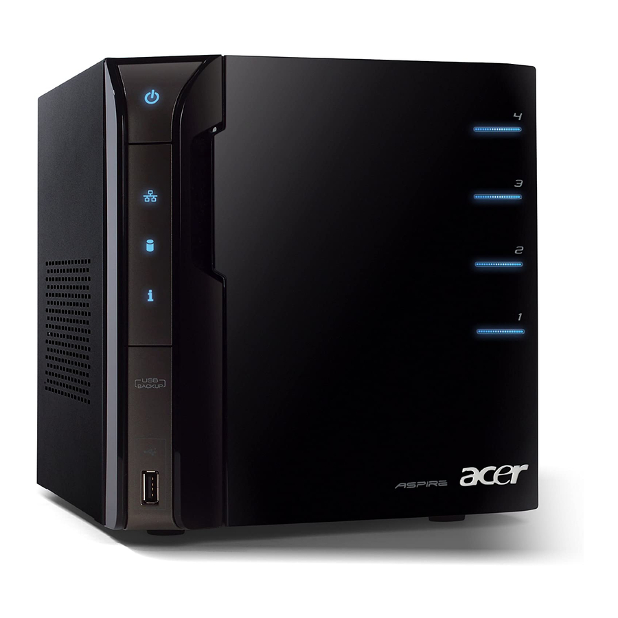
System Tour This section is a virtual tour of the system’s interior and exterior components. Front Panel Icon Component Power button/power indicator Network indicator Hard disk drive (HDD) status indicator System status indicator USB backup button/USB backup indicator USB 2.0 port Front door Open the door to access the hot-swappable HDDs. -
Page 11: Rear Panel
Rear Panel Icon Chapter 1 Component Recovery/reset button eSATA port Gigabit Ethernet port USB ports Power connector Power fan... -
Page 12: Internal Components
Internal Components Component Backplane board Power supply Memory module Mainboard Chapter 1... -
Page 13: System Led Indicators
System LED Indicators Front panel This section describes the different system LED indicators. LED indicator Color Power Blue None Network Blue None HDD status Purple Blue None Chapter 1 LED status Description System is connected to the power supply and turned on and ready for use. - Page 14 LED indicator Color System status Blue Blue and purple USB device Blue backup None HDD access Blue None LED status Description Random blink • System is booting • System is shutting down System initialize operation completed. Random blink System is booting from a USB device (Reserved for BIOS update while boot block has been active) May indicate the following states: •...
- Page 15 Rear panel LED indicator Color LAN port Amber network speed Green None LAN port Green activity LED None Chapter 1 LED status Description 1000 Mbps network access 100 Mbps link network access 10 Mbps link network access Active network link Random blink Transmit or receive activity No network connection...
- Page 16 Chapter 1...
-
Page 17: System Utilities
System Utilities AMI BIOS Setup Utility BIOS setup is a hardware configuration program built into the system's Basic Input/Output System (BIOS). Since most systems are already properly configured and optimized, there is no need to run this utility. You will need to run this utility under the following conditions. -
Page 18: Entering The Bios Setup Utility
Entering the BIOS Setup Utility Before you begin, prepare the following: Wrist grounding strap and conductive mat for preventing electrostatic discharge Philips screwdriver Debug card - Refer to page 44 for details about the debug card. Debug card cable ... -
Page 19: Navigating Through The Setup Utility
Navigating Through the Setup Utility Use the following keys to move around the Setup utility. Left and Right arrow keys – Move between selections on the menu bar. Up and Down arrow keys – Move the cursor to the field you want. ... -
Page 20: Setup Utility Menus
Setup Utility Menus The Setup Main menu includes the following main setup categories. Main Advanced Boot Chipset Exit In the descriptive table following each of the menu screenshots, settings in boldface are the default and suggested settings. - Page 21 Main The Main menu displays basic information about the system and lets you set the system date and time. Parameter Description AMIBIOS Version number of the BIOS Setup Utility. Date when the BIOS Setup Utility was created. Build Date Processor Displays the processor speed in MHz.
- Page 22 Advanced The Advanced menu display submenu options for configuring the function of various hardware components. Select a submenu item, then press <Enter> to access the related submenu screen. Parameter Description IDE Configuration Press <Enter> to select options for the IDE Configuration settings. Hardware Health Press <Enter>...
- Page 23 Boot Use the Boot menu to specify the boot sequence from available devices. Select a submenu item, then press <Enter> to access the related submenu screen. Chapter 2...
- Page 24 Chipset Use the Chipset menu to configure the south bridge chipset. Select the submenu item, then press <Enter> to access the submenu screen. Parameter Description South Bridge Configuration Press <Enter> to select options for the South Bridge Configuration settings. Chapter 2...
- Page 25 Exit The Exit menu lists options for quitting the Setup Utility. Highlight any of the exit options, then press <Enter>. Parameter Description Save Changes and Exit Saves changes made and closes the utility. Keyboard shortcut: F10 Discard Changes and Exit Discards changes made and closes the utility.
- Page 26 Chapter 2...
-
Page 27: System Disassembly
System Disassembly This chapter contains step-by-step procedures on how to disassemble the desktop computer for maintenance and troubleshooting. Disassembly Requirements To disassemble the computer, you need the following tools: Wrist grounding strap and conductive mat for preventing electrostatic discharge Flat-blade screwdriver ... -
Page 28: Pre-Disassembly Procedure
Pre-disassembly Procedure Before proceeding with the disassembly procedure, perform the steps listed below: Turn off the system and all the peripherals connected to it. Unplug the power cord from the power outlets. Unplug the power cord from the system. Unplug all peripheral cables from the system. Place the system unit on a flat, stable surface. -
Page 29: Main Unit Disassembly
Main Unit Disassembly MAIN UNIT DISASSEMBLY TURN OFF POWER HARD DISK DRIVE SYSTEM COVER FRONT I/O BRACKET BACKPLANE BOARD POWER SUPPLY HOUSING FRAME Screw List Code Chapter 3 DRIVE CARRIER MODULE HARD DISK DRIVE A x 3 FRONT BEZEL B x 4 FRONT I/O BOARD BACKPLANE BOARD BRACKET... -
Page 30: Removing The Hard Disk
Removing the Hard Disk Open the front panel. Press to release the hard drive carrier handle. Chapter 3... - Page 31 Flex the carrier handle. Slide the hard drive carrier out of the HDD bay. Chapter 3...
- Page 32 Remove the carrier by gently prying open the left rail of the carrier (1) and lift the hard disk off the carrier (2) . Chapter 3...
-
Page 33: Removing The System Cover
Removing the System Cover Perform the pre-disassembly procedure described on page 20. Remove the three screws (A) that secure system cover. Screw (Quantity) M3-0.5*4 (3) Slide the system cover toward the back of the chassis until the tabs on the cover disengage with the slots on the chassis. -
Page 34: Removing The Front Bezel
Removing the Front Bezel Remove the system cover. Refer to the previous section for instructions. Release the front bezel retention tabs from the chassis interior. Pull the bezel slightly outward, then disconnect the front I/O board cable. Chapter 3... - Page 35 Pull the bezel away from the chassis. Chapter 3...
-
Page 36: Removing The Front I/O Board
Removing the Front I/O Board See “Removing the System Cover” on page 25. See “Removing the Front Bezel” on page 26. Remove the four screws (B) that secures the front I/O bracket. Screw (Quantity) M3*6L (4) Remove the bracket. Color Torque Silver 5.1 to 6.9 kgf-cm... - Page 37 Remove the four screws (C) that secure the front I/O board. Screw (Quantity) M3*0.5*4L (4) Remove the front I/O board. Chapter 3 Color Torque Silver 5.1 to 6.9 kgf-cm Part No. 86.19534.4R0...
-
Page 38: Removing The Backplane Board
Removing the Backplane Board See “Removing the Hard Disk” on page 22. See “Removing the System Cover” on page 25. Disconnect the fan (1), LED (2), and power (3) cables from their backplane board connectors. Disconnect the four HDD SATA cables from their mainboard connectors. Chapter 3... - Page 39 Pull the backplane board bracket out of the chassis. Detach the four HDD SATA cables from their backplane board connectors. Remove the seven screws (C) that secure the backplane board. Screw (Quantity) M3*0.5*4L (7) Chapter 3 Color Torque Silver 5.1 to 6.9 kgf-cm Part No.
- Page 40 Lift the backplane board off the bracket. Chapter 3...
-
Page 41: Removing The Power Supply
Removing the Power Supply See “Removing the Hard Disk” on page 22. See “Removing the System Cover” on page 25. See “Removing the Backplane Board” on page 30. Release the power cables from the cable ties, as shown. Disconnect the 4-pin power cable from its mainboard connector. Chapter 3... - Page 42 Remove the four screws (A) that secure the power supply. Screw (Quantity) M3-0.5*4 (4) With the thumb in the thumb hole, press the tab to release the mainboard carrier from the chassis. Color Torque Silver 5.1 to 6.9 kgf-cm Part No. 86.1A524.4R0 Chapter 3...
- Page 43 Slide the mainboard carrier out slightly, until you have access to the power cable. While pressing the tab on the 24-pin power cable, pull the cable off the mainboard connector. 10. Pull the power supply out of the chassis. Chapter 3...
-
Page 44: Removing The Fan
Removing the Fan See “Removing the Hard Disk” on page 22. See “Removing the System Cover” on page 25. See “Removing the Backplane Board” on page 30. Remove the four screws (A) that secure the fan. Screw (Quantity) M3-0.5*4 (3) Remove the fan. -
Page 45: Removing The Memory Module
Removing the Memory Module See “Removing the Hard Disk” on page 22. See “Removing the System Cover” on page 25. See “Removing the Front Bezel” on page 26. See “Removing the Backplane Board” on page 30. See “Removing the Power Supply” on page 33. See “Removing the Fan”... - Page 46 Press the holding clips on both sides of the DIMM slot outward to release the DIMM (1). 10. Gently pull the DIMM upward to remove it from the DIMM slot (2). Chapter 3...
-
Page 47: Removing The Mainboard
Removing the Mainboard See “Removing the Hard Disk” on page 22. See “Removing the System Cover” on page 25. See “Removing the Front Bezel” on page 26. See “Removing the Backplane Board” on page 30. See “Removing the Power Supply” on page 33. See “Removing the Fan”... -
Page 48: Removing The Hdd Access Led Cables
Removing the HDD Access LED cables See “Removing the Hard Disk” on page 22. See “Removing the System Cover” on page 25. See “Removing the Front Bezel” on page 26. See “Removing the Backplane Board” on page 30. See “Removing the Power Supply” on page 33. See “Removing the Fan”... -
Page 49: System Troubleshooting
System Troubleshooting This chapter provides instructions on how to troubleshoot system hardware problems. Hardware Diagnostic Procedure The system’s diagnostic function monitors system activity and performs IMPORTANT:The diagnostic tests described in this chapter are only intended to test Acer products. Non-Acer products, prototype cards, or modified options can give false errors and invalid system responses. -
Page 50: System Check Procedures
System Check Procedures Power system check If the system will power on, skip this section. Refer to System External Inspection. If the system will not power on, check if the power cable is properly connected to the system and AC source. System external inspection Inspect the LED indicators on the front panel, which can indicate the malfunction. -
Page 51: System Diagnosis
System Diagnosis Hardware diagnostic program The purpose of the hardware diagnostic program is to check hardware problems. It executes simple tests of each hardware component to make sure the hardware is not the source of the problem. If hardware problems, such as a fan, LED board, hard disk drive, memory;... -
Page 52: Debug Card
Test Items Boot from HDD 0 USB disk Backplane board temperature check PQAF system test PQAF memory test PQAF HDD test Read SN from DMI data check End test After the diagnostic routine is completed, the HDD status indicator lights purple indicating the system has passed all diagnostic tests. -
Page 53: Post Code Checkpoints
POST Code Checkpoints The Power-On Self Test (POST) is a BIOS procedure that boots the system, initializes and diagnoses the system components, and controls the operation of the power-on password option. If POST discovers errors in system operations at power-on, it displays error messages, generates a checkpoint code at port 80h or even halts the system if the error is fatal. -
Page 54: Bootblock Recovery Code Checkpoints
Checkpoint Restore CPUID value back into register. The Bootblock-Runtime interface module is moved to system memory and control is given to it. Determine whether to execute serial flash. The Runtime module is uncompressed into memory. CPUID information is stored in memory. - Page 55 POST code checkpoints The POST code checkpoints are the largest set of checkpoints during the BIOS pre-boot process. The following table describes the type of checkpoints that may occur during the POST portion of the BIOS: Checkpoint Disable NMI, Parity, video for EGA, and DMA controllers. Initialize BIOS, POST, Runtime data area.
- Page 56 Checkpoint Programming the memory hole or any kind of implementation that needs an adjustment in system RAM size if needed. Updates CMOS memory size from memory found in memory test. Allocates memory for Extended BIOS Data Area from base memory. Initializes NUM-LOCK status and programs the KBD typematic rate.
- Page 57 Checkpoint Initialize different buses and perform the following functions: Boot Input Device Initialization (function 3); IPL Device Initialization (function 4); General Device Initialization (function 5). Function 3 searches for and configures PCI input devices and detects if system has standard keyboard controller. Function 4 searches for and configures all PnP and PCI boot devices.
-
Page 58: System Status Error Codes
System Status Error Codes NOTE: Perform the FRU replacement or actions in the sequence shown in FRU/Action column, if the FRU replacement does not solve the problem, put the original part back in the computer. Do not replace a non-defective FRU. The error messages in the following table indicate the error signals on the HDD access LED indicators on the front panel and the error symptoms. -
Page 59: Bios Recovery
BIOS Recovery Perform the BIOS recovery if the BIOS flash ROM has become corrupted. The following sections provide instructions on how to recover BIOS settings. To create a BIOS Recovery disk: Prepare a USB storage device. Connect the USB storage device to a USB port on your computer. Copy the target BIOS ROM file to a USB storage device. -
Page 60: Clearing Cmos
Clearing CMOS To clear the BIOS configuration you need to short the JP3 Clear CMOS jumper on the mainboard. Turn off the computer and all attached devices. Remove the system cover. See “Removing the System Cover” on page 25. Locate the JP3 Clear CMOS jumper on the mainboard. Remove the jumper from the default position. -
Page 61: Undetermined Problems
Undetermined Problems The diagnostic problems does not identify which adapter or device failed, which installed devices are incorrect, whether a short circuit is suspected, or whether the system is inoperative. NOTE: Verify that all attached devices are supported by the computer. NOTE: Verify that the power supply being used at the time of the failure is operating correctly. - Page 62 Chapter 4...
-
Page 63: System Block Diagram And Board Layout
Chapter 5 System Block Diagram and Board Layout System Block Diagram Chapter 5... -
Page 64: Board Layout
Board Layout Mainboard Description SATA 1 port SATA 3 port SATA 4 port SATA 2 port USB ports Gigabit Ethernet port (top) USB ports (bottom) eSATA port Recovery/reset button Debug card cable connector Backplane board LED cable connector 22 4-pin power cable connector Fan cable connector (reserved) Description Intel Atom D410/D510 processor... -
Page 65: System Jumpers
System Jumpers Name Clear CMOS jumper System type select jumper Debug/user mode jumper Chapter 5 Location Settings 1-2 Normal (default) 2-3 Clear CMOS 1-2 Aspire system (default) 2-3 Other model Open User mode enabled (default) Closed Debug mode enabled... - Page 66 Chapter 5...
-
Page 67: Fru (Field Replaceable Unit) List
FRU (Field Replaceable Unit) List This chapter offers the FRU (Field Replaceable Unit) list in global configuration of the home server. Refer to this chapter whenever ordering the parts to repair or for RMA (Return Merchandise Authorization). NOTES: When ordering FRU parts, check the most up-to-date information available on your regional web ... -
Page 68: Exploded Diagram
Exploded Diagram Chapter 6... - Page 69 Item Part No. 42.60P02.001 42.60P03.001 34.60P07.001 34.60P05.001 34.60P04.001 47.60M06.001 42.60P01.001 40.60P04.001 40.60P03.001 41.60P02.001 42.55S13.001 42.91F07.001 42.5E309.001 50.60P04.001 33.60P09.001 33.60P05.001 30.60P02.001 86.1A524.4R0 60.60P14.001 86.1A524.4R0 60.60P11.001 33.60P04.001 60.60P02.001 45.00049.001 42.60P11.001 47.60P05.001 38.09008.001 40.60P07.001 60.60P03.001 40.60P06.001 42.60P17.001 42.60P16.001 Chapter 6 Part Name Handle HDD carrier HT-361 Latch HDD carrier HT-361 Axis HDD carrier HT-361 SPG HDD carrier HT-361...
-
Page 70: Fru List
FRU List Component Board Front I/O board FRONT I/O BOARD Backplane board BACKPLANE BOARD Cable Backplane board BACKPLANE BOARD CABLE cable HDD SATA cable HDD SATA CABLE Front I/O board FRONT I/O BOARD CABLE cable HDD access LED HDD LED CABLE cable Power cord POWER CORD 2.5A 250V 1800MM... - Page 71 Component Front I/O bracket FRONT I/O BOARD BRACKET HDD carrier HDD CARRIER Backplane bracket Backplane bracket Mainboard carrier Mainboard carrier System cover System cover MASTER KEY FAN W/FAN RUBBER Hard disk drive HDD SEAGATE 3.5" 7200RPM 1000GB ST31000333AS BRINKS SATA II LF F/W:SD45 HDD SEAGATE 3.5"...
- Page 72 Component Memory MEMORY UNIFOSA UNB-DIMM DDRII 800 1GB GU341G0ALEPR6B2C6CE LF MEMORY UNIFOSA UNB-DIMM DDRII 800MHZ 1GB GU341G0ALEPR6B2C6CE LF Power supply PSU DELTA GPS-200AB B 200W 100-240V S1 Screws SCRW TAP PAN M3*6L 2LEAD NI SCRW MACH P/WS M3*0.5*4L NI SCRW MACH PAN M3-0.5*4 NI Part Name DIMM 1G GU341G0ALEPR6B2C6CE...
-
Page 73: Technical Specifications
Technical Specifications This section provides technical specifications for the system. Processor Item Specification Type Onboard Intel Atom series Model number D410 Core Threads Clock speed (GHz) 1.66 L2 cache size 512 KB Bus type Manufacturing tech 45 nm (CMOS) Max TDP (W) Socket type Micro-FCBGA8559 Embedded... - Page 74 System Memory Item Memory type Organization Pin count DIMM sockets DIMM size Minimum memory Maximum memory Vendor Model name System BIOS Item BIOS vendor BIOS version Flash memory PCI Interface Item PCI Express controller Number of slots Network Interface Item LAN controller Supports LAN protocol LAN connector type...