Advertisement
Quick Links
Download this manual
See also:
Owner's Manual
This manual has been provided for the use of authorized YAMAHA Retailers and their service personnel.
It has been assumed that basic service procedures inherent to the industry, and more specifically YAMAHA Products, are already known and understood by the users,
and have therefore not been restated.
WARNING:
Failure to follow appropriate service and safety procedures when servicing this product may result in personal injury, destruction of expensive
components, and failure of the product to perform as specified. For these reasons, we advise all YAMAHA product owners that any service required
should be performed by an authorized YAMAHA Retailer or the appointed service representative.
IMPORTANT:
The presentation or sale of this manual to any individual or firm does not constitute authorization, certification or recognition of any applicable
technical capabilities, or establish a principle-agent relationship of any form.
The data provided is believed to be accurate and applicable to the unit(s) indicated on the cover. The research, engineering, and service departments of YAMAHA are
continually striving to improve YAMAHA products. Modifications are, therefore, inevitable and specifications are subject to change without notice or obligation to
retrofit. Should any discrepancy appear to exist, please contact the distributor's Service Division.
WARNING:
Static discharges can destroy expensive components. Discharge any static electricity your body may have accumulated by grounding yourself to the
ground buss in the unit (heavy gauge black wires connect to this buss).
IMPORTANT:
Turn the unit OFF during disassembly and part replacement. Recheck all work before you apply power to the unit.
I CONTENTS
TO SERVICE PERSONNEL ..........................................
SPECIFICATIONS ..........................................................
DIMENSIONS .................................................................
INTERNAL VIEW ...........................................................
REAR PANELS ..............................................................
DISASSEMBLY PROCEDURES ...............................
1 0 0 6 8 7
STEREO CASSETTE DECK
KX-E100
SERVICE MANUAL
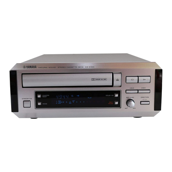
NATURAL SOUND STEREO CASSETTE DECK KX-E100
COUNTER
RESET
STANDBY/ON
MODE
IMPORTANT NOTICE
ADJUSTMENT ...........................................................
1
DISPLAY DATA ...........................................................
1
2
IC DATA .................................................................
2
BLOCK DIAGRAM .......................................................
PRINTED CIRCUIT BOARD ..................................
3
SCHEMATIC DIAGRAM ..............................................
4~5
PARTS LIST ...........................................................
DOLBY NR
REC LEVEL
DIRECTION
REC/
PAUSE
MIN
MAX
11~12
14~21
23~31
P.O.Box 1, Hamamatsu, Japan
6~9
10
13
22
Advertisement

Related Manuals for Yamaha KX-E100

Summary of Contents for Yamaha KX-E100
- Page 1 The data provided is believed to be accurate and applicable to the unit(s) indicated on the cover. The research, engineering, and service departments of YAMAHA are continually striving to improve YAMAHA products. Modifications are, therefore, inevitable and specifications are subject to change without notice or obligation to retrofit.
-
Page 2: Specifications
KX-E100 I TO SERVICE PERSONNEL AC LEAKAGE WALL EQUIPMENT TESTER OR OUTLET UNDER TEST EQUIVALENT Critical Components Information. Components having special characteristics are marked and must be replaced with parts having specifications equal to those originally installed. INSULATING TABLE WARNING: CHEMICAL CONTENT NOTICE! The solder used in the production of this product contains LEAD. - Page 3 KX-E100 I DIMENSIONS 11(7/16") 217(8-9/16") Unit : mm (inch) I INTERNAL VIEW 1 MAIN P.C.B. (4) 2 Cassette Mechanism Unit 3 MAIN P.C.B. (1) 4 MAIN P.C.B. (2) 5 MAIN P.C.B. (3)
- Page 4 KX-E100 I REAR PANELS M U, C models M R model M A model M B, G models...
- Page 5 KX-E100 I DISASSEMBLY PROCEDURES Remove parts in disassembly order as numbered. 1. Removal of Top Cover a. Remove 4 screws (1) and 4 screws (2) in Fig. 1. b. Lift the Top Cover at the rear and move it rear-ward slantingly.
- Page 6 KX-E100 4. Removal of Cassette Mechanism F/R Belt a. Remove 4 screws (6) in Fig. 3. b. Detach the hook in Fig. 3 and then pull out the Cassette Mechanism. 5. Removal of Main Motor Remove 2 screws (7) in Fig. 3.
- Page 7 KX-E100 I ADJUSTMENTS G Torque meter 1. Before adjustment G Since head magnetization, dust accumulations, etc. are TW-2111A (TX911580) ... Take up/back tension (FWD) likely to introduce error in the various characteristics, it TW-2121A (TX911570) ... Take up/back tension (RVS) is very important that the heads are properly CT-160L (TX911120) ........
- Page 8 KX-E100 Rec out L : ch 1 Azimuth adjustment Rec out R : ch 2 screw. (REVERSE) DC input, X-Y (Resurge) mode 0.2V 0.2V Azimuth adjustment screw. (FORWARD) Fig. B MAIN (1) VR101 VR103 VR104 VR202 VR201 VR204 VR203 MAIN (2) RECORDING LEVEL &...
- Page 9 KX-E100 MECHANICAL ADJUSTMENT Item to be Instrument Adjustment Step Tape Mode Rating Remarks Adjusted required part Check each CT-160L (FF, REW) Torque meter FF REW FF, REW torque : within 70 ~ 150g/cm. torque TW-2111A (FWD) PLAY Take up torque : 30 ~ 70g/cm.
- Page 10 KX-E100 <Recording section> Item to be Instrument Measurement Points of Adjustment Step Tape Mode Rating Adjusted required conditions measurement parts Recording AC-514 ACVM Input 315 Hz Signal to LINE OUT VR203 (L ch) Adjust for equal record and level High...
- Page 11 KX-E100 I DISPLAY DATA G VO301 : BJ707GNK (V358690) PATTERN AREA G PIN CONNECTION Pin No. 1 2 3 4 5 6 7 8 9 10 11 12 13 14 15 16 17 18 19 20 21 22 23 24 25 26 27 28 29 30 31...
- Page 12 KX-E100 I IC DATA IC205 : M38B57M6-135FP (XW379A00) /FLD RDV2 CLK22 /FLD CLK21 /TxD /FLD /RxD /FLD /FLD CLK12 /FLD CLK11 /FLD OUT1 /FLD /FLD /FLD /FLD STB1 /INT /FLD BUSY1 /FLD RDY1 /RTP /FLD /RTP /FLD I/O Port Port P0 (8)
- Page 13 KX-E100 Pin No. PORT RESISTOR Pin No. PORT RESISTOR P75/AN5 Mecha SW1 AD(PLAY, Half) P32/FL26 O FL-DIG3 ON : H P74/AN4 Loading SW AD(IN,OUT) P31/FL25 O FL-DIG2 ON : H P73/AN3 Meter L AD(-30 – +6) P30/FL24 O FL-DIG1 ON : H...
- Page 14 KX-E100 I BLOCK DIAGRAM E-13/J-11...
- Page 15 KX-E100 I PRINTED CIRCUIT BOARD P.C.B. MAIN (1) (Lead Type Devices) To/From : MAIN (2) To : MAIN (2) G Semiconductor Location Ref. No. Location D108 D115 D116 D117 D118 Q101 Q102 Q103 Q104 Q105 Q106 Q107 Q108 Q109 Q110...
- Page 16 KX-E100 I PRINTED CIRCUIT BOARD P.C.B. MAIN (1) (Surface Mount Devices) G Semiconductor Location Ref. No. Location D101 D102 D103 D104 D105 D106 D107 D109 D110 D111 D112 D113 D114 D119 P.C.B. MAIN (4) (Lead Type Devices) To : MAIN (1) P.C.B.
- Page 17 KX-E100 I PRINTED CIRCUIT BOARD PLAYBACK LEVEL ADJ. RECORDING LEVEL ADJ. G Semiconductor Location To : MAIN (3) Ref. No. Location P.C.B. MAIN (2) (Lead Type Devices) To/From : MAIN (3) Q201 To/From : R/P & ER HEADS Q202 Q203...
- Page 18 KX-E100 I PRINTED CIRCUIT BOARD From : MAIN (2) P.C.B. MAIN (3) (Lead Type Devices) COUNTER RESET DOLBY NR DIRECTION MODE REC/ PAUSE STANDBY/ON REC LEVEL To/From : MAIN (2) P.C.B. MAIN (3) (Surface Mount Devices) E-20/J-18 E-21/J-19...
- Page 19 KX-E100 SCHEMATIC DIAGRAM IC101 : LB1641 IC102 : BA6138 Motor Driver 1/2 Power Compressor Amp. The voltages are measured using normal tape in the PLAY mode (no-signal condition). Only the voltage in ( ) are in the REC mode. PLAYBACK LEVEL Vreg ADJ.
- Page 20 KX-E100 I WARNING PARTS LIST Components having special characteristics are marked s and must be replaced with parts having specifications equal to those originally in- stalled. I ELECTRICAL PARTS G Carbon resistors (1/6W or 1/4W) are not included in the ELECTRICAL PARTS List.
- Page 21 KX-E100 Note on the Main P.C.B. (Parts marked with "%") Of the main P.C.B. part Nos., only the silver (SI) type part Nos. are included in the table. The only different part between the gold (GD) and silver (SI) type parts is the sheet/FL that is attached to the fluorescent character display tube.
- Page 22 KX-E100 Schm Schm Ref. PART NO. Description Ref. PART NO. Description D206 VT332900 DIODE 1SS355 R158 HV753560 R.CAR.FP 1/4W D207 VT332900 DIODE 1SS355 SW301 VG392900 SW.TACT SKHVAA D208 VT332900 DIODE 1SS355 SW302 VG392900 SW.TACT SKHVAA D209 VT332900 DIODE 1SS355 SW303 VG392900 SW.TACT SKHVAA Fi201 V3733300 FLTR.LC.MP...
- Page 23 KX-E100 Schm Schm Ref. PART NO. Description Ref. PART NO. Description RD257200 R.CAR.CHP 1/10W RD257220 R.CAR.CHP 1/10W RD257240 R.CAR.CHP 1/10W RD257270 R.CAR.CHP 1/10W RD257330 R.CAR.CHP 1/10W RD257390 R.CAR.CHP 1/10W RD257430 R.CAR.CHP 1/10W RD257470 R.CAR.CHP 1/10W RD257750 R.CAR.CHP 1/10W RD258100 R.CAR.CHP...
- Page 24 KX-E100 Note on the Main P.C.B. (Parts marked with “%”) I EXPLODED VIEW I MECHANICAL PARTS Of the main P.C.B. part Nos., only the silver (SI) type part Nos. are included in the table. The only different part between the gold (GD) and silver (SI) type parts is the sheet/FL that is attached to the fluorescent character display tube.
- Page 25 KX-E100 I EXPLODED VIEW (Loading Mechanism) I EXPLODED VIEW (Cassette Deck Mechanism) Ref. PART NO. Description Remarks Markets AAX07650 CASSETTE DECK MECH. UINT F511638 AAX07550 PLATE HD BLOCK F513831 AAX07450 MTR MAIN BLOCK F525327 AAX07470 PCB CONTROL BLOCK F567626 AAX07490 CLUTCH ASS’Y BLOCK F522037 Ref.
- Page 26 KX-E100 Parts List for Carbon Resistors Value 1/4W Type Part No. 1/6W Type Part No. Value 1/4W Type Part No. 1/6W Type Part No. 1.0 Ω 3100 3100 10 kΩ 7100 7100 HJ35 HF85 HF45 HF45 1.8 Ω ❊ 3180 11 kΩ...
- Page 27 KX-E100...