Yamaha CD-S2000 Service Manual
Super audio cd player
Hide thumbs
Also See for CD-S2000:
- Owner's manual (182 pages) ,
- Service manual (59 pages) ,
- User manual (30 pages)
Table of Contents
Advertisement
This manual has been provided for the use of authorized YAMAHA Retailers and their service personnel.
It has been assumed that basic service procedures inherent to the industry, and more specifically YAMAHA Products, are already
known and understood by the users, and have therefore not been restated.
WARNING:
IMPORTANT:
The data provided is believed to be accurate and applicable to the unit(s) indicated on the cover. The research, engineering, and
service departments of YAMAHA are continually striving to improve YAMAHA products. Modifications are, therefore, inevitable
and specifications are subject to change without notice or obligation to retrofit. Should any discrepancy appear to exist, please
contact the distributor's Service Division.
WARNING:
IMPORTANT:
I CONTENTS
TO SERVICE PERSONNEL ...................................... 2-3
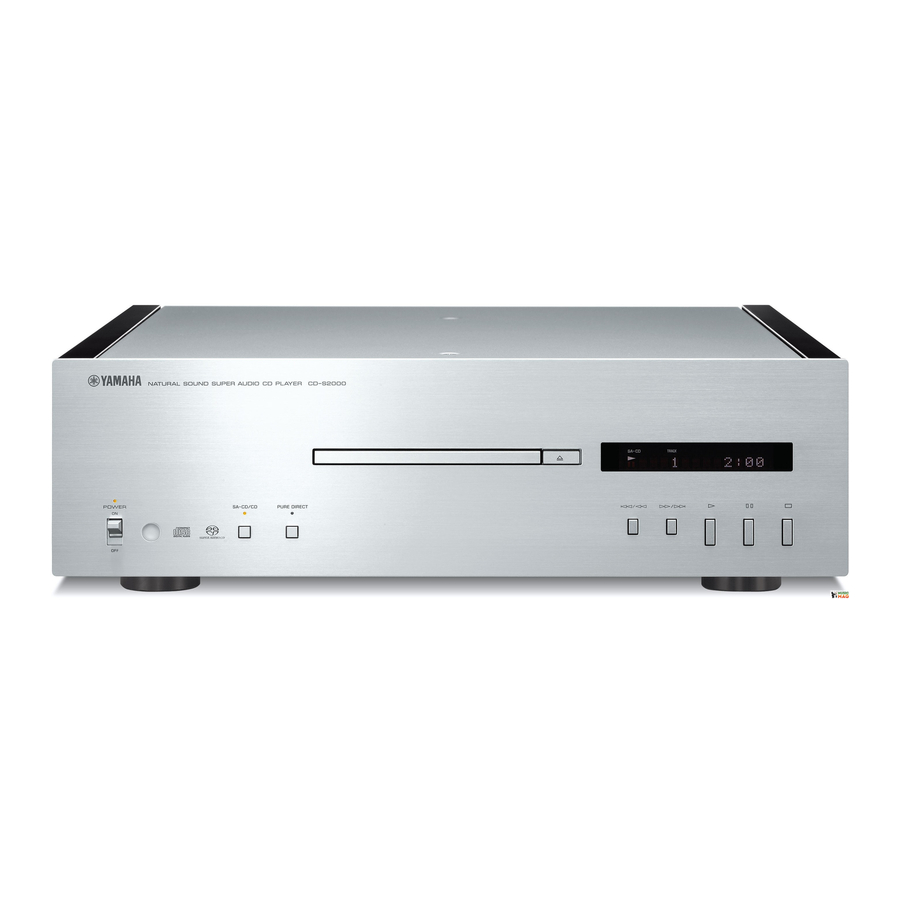
FRONT PANEL .............................................................. 5
REAR PANELS .......................................................... 5-7
REMOTE CONTROL PANEL ........................................ 8
SPECIFICATIONS /
INTERNAL VIEW ........................................................... 9
DISASSEMBLY PROCEDURES /
.......................................... 17
UPDATING FIRMWARE /
ファームウェアの書き込み
............................................................................ 18-24
1 0 1 0 7 8
SUPER AUDIO CD PLAYER
CD-S2000
Failure to follow appropriate service and safety procedures when servicing this product may result in personal
injury, destruction of expensive components, and failure of the product to perform as specified. For these reasons,
we advise all YAMAHA product owners that any service required should be performed by an authorized
YAMAHA Retailer or the appointed service representative.
The presentation or sale of this manual to any individual or firm does not constitute authorization, certification or
recognition of any applicable technical capabilities, or establish a principle-agent relationship of any form.
Static discharges can destroy expensive components. Discharge any static electricity your body may have
accumulated by grounding yourself to the ground buss in the unit (heavy gauge black wires connect to this buss).
Turn the unit OFF during disassembly and part replacement. Recheck all work before you apply power to the unit.
...................................... 8-9
........... 10-16
2007
This manual is copyrighted by YAMAHA and may not be copied or
redistributed either in print or electronically without permission.
SERVICE MANUAL
IMPORTANT NOTICE
DISPLAY DATA ........................................................... 25
IC DATA ................................................................. 26-28
PIN CONNECTION DIAGRAMS ............................ 29-30
BLOCK DIAGRAM ....................................................... 31
PRINTED CIRCUIT BOARDS ................................ 32-40
SCHEMATIC DIAGRAMS ...................................... 41-45
REPLACEMENT PARTS LIST .............................. 47-58
REMOTE CONTROL .................................................... 59
All rights reserved.
P.O.Box 1, Hamamatsu, Japan
'07.12
Advertisement
Table of Contents

Related Manuals for Yamaha CD-S2000


Summary of Contents for Yamaha CD-S2000
-
Page 1: Table Of Contents
This manual has been provided for the use of authorized YAMAHA Retailers and their service personnel. It has been assumed that basic service procedures inherent to the industry, and more specifically YAMAHA Products, are already known and understood by the users, and have therefore not been restated. -
Page 2: To Service Personnel
CD-S2000 I TO SERVICE PERSONNEL AC LEAKAGE WALL EQUIPMENT TESTER OR 1. Critical Components Information OUTLET UNDER TEST EQUIVALENT Components having special characteristics are marked s and must be replaced with parts having specifications equal to those originally installed. 2. Leakage Current Measurement (For 120V Models Only) - Page 3 CD-S2000 Laser Diode Properties • Material: • Laser Output: SA-CD Semiconductor laser (AlGaInP) SA-CD 5 mW (max.) Semiconductor laser (AlGaAs) 7 mW (max.) • Wavelength: SA-CD 650 nm 780 nm B, G models Warning for power supply The primary side of the power supply carries live mains voltage when the player is connected to the mains even when the player is switched off ! This primary area is not shielded so it is possible to touch copper tracks and/or components when servicing the player.
-
Page 4: Prevention Of Electrostatic Discharge
CD-S2000 I PREVENTION OF ELECTROSTATIC DISCHARGE Some semiconductor (solid state) devices can be damaged easily by static electricity. Such components commonly are called Electrostatically Sensitive (ES) Devices. Examples of typical ES devices are integrated circuits and some field-effect transis- tors and semiconductor “chip” components. The following techniques should be used to help reduce the incidence of compo- nent damage caused by electro static discharge (ESD). -
Page 5: Front Panel
CD-S2000 I FRONT PANEL CD-S2000 (U, C, R, T, K, A, B, G, L, J models) I REAR PANELS CD-S2000 (U, C models) CD-S2000 (R model) - Page 6 CD-S2000 CD-S2000 (T model) CD-S2000 (K model) CD-S2000 (A model)
- Page 7 CD-S2000 CD-S2000 (B, G models) CD-S2000 (L model) CD-S2000 (J model)
-
Page 8: Remote Control Panel
CD-S2000 I REMOTE CONTROL PANEL I SPECIFICATIONS / 参考仕様 CDX5 I Audio Section / オーディオ部 Frequency Response / 周波数特性 SA-CD ............2 Hz to 50 kHz (-3 dB) CD ................2 Hz to 20 kHz Total Harmonic Distortion + Noise (1 kHz) / 高調波歪率 (1 kHz)... -
Page 9: Internal View
CD-S2000 • DIMENSIONS / 寸法図 435 (17-1/8") Unit: mm (inch) 単位:mm (インチ) I INTERNAL VIEW 1 POWER TRANSFORMER for DIGITAL/ LOADER 2 POWER TRANSFORMER for AUDIO 3 POWER (2) P.C.B. (R, L models) 4 POWER (1) P.C.B. 5 LOADER ASS'Y 6 AUDIO P.C.B. -
Page 10: 分解手順
CD-S2000 I DISASSEMBLY PROCEDURES / 分解手順 (番号順に部品を取り外してください。) (Remove parts in the order as numbered.) AC電源コンセントから、電源コードを抜いてください。 Disconnect the power cable from the AC outlet. 1. パネルサイド L/Rの外し方 1. Removal of Panel Side L/R a. 1 のネジ2本、サラバネL、ワッシャーサイドを外しま a. Remove 2 screws (1), coned disc spring L and washer す。... - Page 11 CD-S2000 3. フロントパネルの外し方 3. Removal of Front Panel a. Using a flatblade screwdriver, move the slider at the bot- a. マイナスドライバーで底面のスライダーを下図の矢印 tom in the direction of the arrow shown below. (Fig. 2) の方向に動かします。 (Fig. 2) ※ このとき、トレーは押し出されません。 At this time, the tray is not pushed out.
- Page 12 CD-S2000 4. フロントフレームASSYの外し方 4. Removal of Front Frame ass’y a. 8 のネジ4本、 9 のネジ2本を外し、フレームトップを a. Remove 4 screws (8), 2 screws (9) (B, G models) and then remove the frame top. (Fig. 4) 取り外します。 (Fig. 4) b. 0 のネジ9本を外します。 (Fig. 4)...
- Page 13 CD-S2000 6. Removal of Loader ass’y 6. ローダーASSYの外し方 a. D のネジ4本を外し、サポートAUDIOを取り外しま a. Remove 4 screws (D) and then remove the support R, L models す。 (Fig. 4) audio. (Fig. 4) b. Remove CB301-302, CB612 and CB903. (Fig. 4) b. CB301-302、CB612、CB903を外します。 (Fig. 4)...
- Page 14 CD-S2000 G Disassembly of Loader Ass’y 7. Removal of DIGITAL P.C.B. 7. DIGITAL P.C.B.の外し方 ● ローダーASSYの分解手順 a. K のネジ3本を外します。 (Fig. 8) a. Remove 3 screws (K). (Fig. 8) 1. Removal of Module Board 1. モジュール基板の外し方 b. L のネジ4本を外します。 (Fig. 5)...
- Page 15 CD-S2000 2. DVDトラバースメカおよびステッピングモー 2. Removal of DVD Traverse Mechanism and Stepping Motor. ターの外し方 ※ 新しいDVDトラバースメカに交換する場合、 When installing a new DVD traverse mecha- ピックアップユニットのショート箇所のハンダ nism, remove the solder from the shorted point of pick up unit using an electrostatic を静電気対策ハンダごてで取り除いてくださ い。...
- Page 16 CD-S2000 ・ 新しいステッピングモーターを取り付ける場合: • When installing a new Stepping Motor: 新しいステッピングモーターを取り付ける場合に Before installing a new stepping motor, apply は、新しいステッピングモーターのスクリュー部分 grease to its screw. にグリスを塗布します。 Recommended grease: PN-397 (Part No.: AAX89650) 推奨グリス:PN-397 ( 部品番号:AAX89650) a. Apply grease to the screw at 3 points as shown a.
-
Page 17: テストモード
CD-S2000 I TEST MODE / テストモード G Starting Test Mode ● テストモード起動 To activate the TEST mode, set the “POWER ON/ 本機の下図に示すキーを同時に押しながら “POWER OFF” switch to the ON position while pressing the ON/OFF” スイッチをONにすると、テストモードが起 keys of this unit as shown below at the same time. - Page 18 CD-S2000 I UPDATING FIRMWARE / ファームウェアの書き込み Writing to the microprocessor マイコンへの書き込み After replacing the following parts with the replacement 下記の部品をサービス部品に交換した場合、下記の手順 により最新のファームウェアの書き込みを行ってくださ parts, update the latest firmware according to the following procedure. い。 DIGITAL P.C.B. DIGITAL P.C.B. Microprocessor (IC302) of DIGITAL P.C.B.
- Page 19 CD-S2000 G Operation Procedure ● 操作方法 1. 本機の電源を切り、電源コードをACコンセントから抜 1. Turn off the power of this unit and disconnect the power cable from the AC outlet. きます。 2. 1 のネジ2本を外します。 (Fig. 1) 2. Remove 2 screws (1). (Fig. 1) 3. Lift the panel side R a little, release hooks at 3 loca- 3.
- Page 20 CD-S2000 7. Start up FlashSta.exe, the screen will appear as 7. FlashSta.exeを立ち上げます。 すると下記の画面が表示されます。 (Fig. 2) shown below. (Fig. 2) Select Internal flash memory Internal flash memoryを選択します Select the port of RS-232C 接続しているRS-232Cポートを選択します Fig. 2 8. Select the port and data to be transmitted. (Fig. 2) 8.
- Page 21 CD-S2000 10. Click [E.P.R.], the screen appears as shown below. 10.[E.P.R] をクリックすると、下記の画面が表示されます。 (Fig. 4) (Fig. 4) [OK] をクリックし、書き込みを開始します。 Click [OK] and start writing. (Fig. 4) (Fig. 4) Writing being executed. 書き込み中 Fig. 4 11. プログラムの送信が終了すると、下記の画面が表示さ 11. When the program transmission is completed, the screen appears as shown below.
-
Page 22: Test Mode
CD-S2000 12. Set the “POWER ON/OFF” switch of this unit to the 12. 本機の “POWER ON/OFF” スイッチをOFFにします。 13. 本機の電源コードをACコンセントから抜きます。 OFF position. 13. Disconnect the power cable of this unit from the AC 14.“FlashSta.exe” を終了します。 outlet. 15. RS232Cクロスケーブル、RS232C変換アダプター カード電線を取り外します。 14. End “FlashSta. exe.”... - Page 23 CD-S2000 Writing to the Module Board モジュール基板への書き込み After replacing the Module board with the replacement part, モジュール基板をサービス部品に交換した場合、最新の be sure to write the latest firmware. ファームウェアの書き込みを行ってください。 G Required Tools ● 必要なツール Firmware CD ファームウェアCD ※ ファームウェアCDは、PCへ最新のファームウェ To make the firmware CD, download the latest firm- アを指定のダウンロード先からダウンロードして...
- Page 24 CD-S2000 6. After about 5 seconds, the tray opens automati- 6. 約5秒後、自動でトレイが開きます。 ファームウェアCDを取り出します。 cally. Remove the firmware CD. ※ このとき、本機はファームウェアの書き込み At this time, do not turn off the power as writ- を継続しています。電源は切らないでくださ い。 ing of the firmware is going on in this unit.
-
Page 25: Display Data
CD-S2000 I DISPLAY DATA G V800 : 13-ST-81GINK (DIGITAL (2) P.C.B.) G PIN CONNECTION Pin No. Connection Q13G Pin No. Connection RESET Pin No. Connection LGND PGND Note: 1) F1, F2 ..Filament 2) NP ..No pin 3) NX ..No extended pin 4) DL .. -
Page 26: Ic Data
CD-S2000 I IC DATA IC302: M30302FAPFP (DIGITAL (1) P.C.B.) Single-chip 16-bit microprocessor Port P0 Port P1 Port P2 Port P3 Port P4 Port P5 Port P6 Peripheral function System clock generator A/D converter Timer (16-bit) (10-bit 18-channel COUT Input (timer A) x3... - Page 27 CD-S2000 Port Name Function Name Detail of Function P9_6/ANEX1 (No connected) P9_5/ANEX0 CLAMP_SW2 Clamp SW2 P9_4 CLAMP_SW1 Clamp SW1 P9_3 TRAY_SW4 P9_2/TB2IN TRAY_SW3 Tray SW3 / Loader mechanism specification confirm P9_1/TB1IN TRAY_SW2 Tray SW2 P9_0/TB0IN TRAY_SW1 Tray SW1 BYTE CNVSS...
- Page 28 CD-S2000 Port Name Function Name Detail of Function P3_5/A13 (No connected) P3_4/A12 POWER_LED Indicator of power supply P3_3/A11 PUREDIRECT_LED Indicator of pure direct P3_2/A10 SACD_LED Indicator of SACD P3_1/A9 FL_RES FL control VCC2 P3_0/A8 FL_CS FL control P2_7/A7 (No connected)
-
Page 29: Pin Connection Diagrams
CD-S2000 I PIN CONNECTION DIAGRAMS • ICs BA08CC0T BD4829G-TR LB1641 M30302FAPFP NE5532DR NJM7808FA NJM78L12UA NJM78M05FA OP275GSR 3: OUT 1: INPUT 1: OUTPUT 2: GND 1: IN 2: GND 2: GND 3: OUTPUT 3: INPUT PCM1792ADBR TC74VHC08F TC74HCT08AF TC74VHC157F TC7SH08F TS7ST00F TC7WU04F •... - Page 30 CD-S2000 • Transistors 2SA1037K 2SD1938F 2SA2168 2SC2412K 2SC2878 2SC5291 2SD2014 2SK208-Y DTA114EKA KTC3198 DTC114EKA 1: GND 2: IN 3: OUT...
-
Page 31: Block Diagram
CD-S2000 I BLOCK DIAGRAM AUDIO • See page 44 → IC19, 20 IC14 IC18 SCHEMATIC DIAGRAM Q10, 16 PCM1792ADBR Q11, 17 NE5532DR IC10 AUDIO IC15 NE5532DR Q9, 15 IC21, 22 IC16 Q14, 20 LOADER ASS'Y IC303 IC304 PCM1792ADBR Q13, 19... -
Page 32: Printed Circuit Boards
CD-S2000 I PRINTED CIRCUIT BOARDS DIGITAL (1) P.C.B. (Side A) • Semiconductor Location Ref no. Location Ref no. Location IC303 IC304 (Writing port) DIGITAL (5) (CB901) DGND DGND FL_RESET FL_CLK FL_DATA FL_CS KEY2 KEY1 LED_POWER KEY0 +3.3 LED_PDIRECT LED_SACD S1 TRAY CLOSE... - Page 33 CD-S2000 DIGITAL (1) P.C.B. (Side B) • Semiconductor Location Ref no. Location Ref no. Location D301 IC301 D302 IC302 D303 IC305 D304 IC306 D305 IC307 D307 IC308 D309 Q301 D310 Q302...
- Page 34 CD-S2000 DIGITAL (2) P.C.B. (Side A) DIGITAL (4) P.C.B. (Side A) • Semiconductor Location POWER indicator Ref no. Location Ref no. Location D801 D803 D802 LED_POWER CB800 DIGITAL (5) P.C.B. (Side A) DIGITAL (1) (CB307) LED_SACD/CD LED_PDIRECT LED_POWER KEY2 +3.3...
- Page 35 CD-S2000 DIGITAL (2) P.C.B. (Side B) DIGITAL (4) P.C.B. (Side B) • Semiconductor Location Ref no. Location Ref no. Location D804 Q802 IC802 Q803 Q800 Q804 Q801 DIGITAL (5) P.C.B. (Side B) DIGITAL (3) P.C.B. (Side B)
- Page 36 CD-S2000 Module board AUDIO P.C.B. (Side A) OUTPUT BALANCED OUT IC19 IC18 IC14 +12VL AGND -12VL ANALOG OUT POWER (1) IC20 (CB608) ANALOG OUT IC10 IC13 IC12 IC21 +12VL AGND -12VL IC16 BALANCED OUT POWER (1) (CB609) IC22 DGND DGND •...
- Page 37 CD-S2000 • Semiconductor Location Ref no. Location Ref no. Location AUDIO P.C.B. (Side B)
- Page 38 CD-S2000 DIGITAL (1) (W306) POWER (1) P.C.B. (Side A) POWER TRANSFORMER DGND -12M ACFL1 AC IN ACFL2 MGND LOADING MOTOR- LOADING MOTOR+ FLGND ACFL ACFL DGND MUTE_POWER DGND DGND +3.3 POWER (3) (CB601) DGND DIGITAL (1) W608A (W309) W606A A+12L...
- Page 39 CD-S2000 POWER (1) P.C.B. (Side B) • Semiconductor Location Ref no. Location Ref no. Location Ref no. Location Ref no. Location Ref no. Location D606 D612 D617 D622 Q603 D608 D613 D618 D623 Q604 D609 D614 D619 D624 Q610 D610...
- Page 40 CD-S2000 POWER (2) P.C.B. (Side A) POWER (3) P.C.B. (Side A) R, L models VOLTAGE SELECTOR POWER (1) (W604A, W606B) 220V 120V CB601 230- 240V 110V POWER ON/OFF switch W603B W602B W605B W604B W601B CB615 POWER (1) (W601A, W602A, W603A, W604A, W605A, W606A) POWER (2) P.C.B.
-
Page 41: Schematic Diagrams
CD-S2000 SCHEMATIC DIAGRAMS DIGITAL 1/3 CB301 W306 Page 45 to POWER (1)_CB610 To Module board IC308 IC308 CB307 MICROPROCESSOR IC306 IC308 IC301 IC306 IC302 IC308 IC306 IC306 Page 43 CB302 to DIGITAL (5)_CB901 IC307: TC7WU04F Triple inverter To Module board... - Page 42 CD-S2000 DIGITAL 2/3 DIGITAL (2) 0.6 0.8 30.3 30.3 CB800 Page 43 to DIGITAL (5)_CB902 CB802 W801 W803A W803B SAN-PH DIGITAL (4) Key detection for AD port Key INPUT (A/D) pull-up resistance 10 k-ohms + 820 + 3.3 k + 12.0 k 0 –...
- Page 43 CD-S2000 DIGITAL 3/3 DIGITAL (5) CB901 CB902 Page 42 to DIGITAL (2)_CB800 Page 41 to DIGITAL (1)_CB307 CB903 To LOADER ass'y # All voltages are measured with a 10MΩ/V DC electronic voltmeter. # Components having special characteristics are marked s and must be replaced with parts having specifications equal to those originally installed.
- Page 44 CD-S2000 AUDIO 12.5 IC11 12.4 12.5 12.4 12.5 -0.9 IC19 12.5 Page 45 OUT L IC14 12.5 -0.9 to POWER (1)_CB608 IC15 ANALOG OUT L IC15 -12.4 -12.3 -12.3 -12.4 -12.4 -4.8 IC19 CD IN -12.3 -12.4 OUT + IC18 -12.3...
- Page 45 CD-S2000 POWER POWER ON/OFF 17.0 14.9 14.3 12.5 POWER (3) -17.2 17.0 CB608 Page 44 to AUDIO_CB5 -5.5 -5.0 -5.5 -14.4 -12.4 AC27.6 U, C, T, K, A, B, G, J models -15.3 CB613 CB614 CB606 CB603 -17.2 C618 WN19300...
-
Page 46: Replacement Parts List
CD-S2000 I REPLACEMENT PARTS LIST • ELECTRICAL COMPONENT PARTS WARNING G Components having special characteristics are marked s and must be replaced with parts having specifications equal to those originally installed. G The chip resistor is not supplied as a replacement part. - Page 47 CD-S2000 P.C.B. DIGITAL Ref No. Part No. Description Remarks Markets 部 品 名 ランク WM129600 P.C.B. DIGITAL PCB DIGITAL CB301 WK469100 CN.FMN FMN 29P TE FMNコネクター CB302 VB390100 CN.BS.PIN ベースピン CB303 VQ047300 CN.BS.PIN FFCコネクター CB307 VQ047800 CN.BS.PIN FFCコネクター CB308 VP682300 CN.BS.PIN FFCコネクター CB800 VQ045000 CN.BS.PIN...
- Page 48 CD-S2000 P.C.B. DIGITAL and P.C.B. AUDIO Ref No. Part No. Description Remarks Markets 部 品 名 ランク C816-817 WG780700 C.EL 47uF ケミコン C818-820 US064100 C.CE.CHP 0.01uF 50V B チップセラコン C830 US126100 C.CE.CHP チップセラコン C831 WG888300 C.CE.M.CHP 10uF 6.3V チップ積層セラコン C832 US065100 C.CE.CHP 0.1uF...
- Page 49 CD-S2000 P.C.B. AUDIO Ref No. Part No. Description Remarks Markets 部 品 名 ランク C18-29 WE102900 C.PP 0.01uF 100V PPコン C30-41 UU237470 C.EL 47uF ケミコン FW UU237100 C.EL 10uF ケミコン FW C46-47 WN440600 C.EL 470uF ケミコン KW C48-49 WE102900 C.PP 0.01uF 100V PPコン C50-51 UU238100 C.EL 100uF ケミコン...
- Page 50 CD-S2000 P.C.B. AUDIO Ref No. Part No. Description Remarks Markets 部 品 名 ランク X5482A00 IC NE5532DR OP AMP アンプIC IC10 XT475A00 IC TC74VHC157F(EL,F) ロジックIC IC11 X9430A00 IC PQ033ES3MXP 電源IC IC12-13 XT014B00 IC TC74VHC08F(EL,K,F) IC IC14-18 X5482A00 IC NE5532DR OP AMP アンプIC...
- Page 51 CD-S2000 P.C.B. AUDIO and P.C.B. POWER Ref No. Part No. Description Remarks Markets 部 品 名 ランク R124-126 WA621700 R.MTL.FLM 270Ω 金属被膜抵抗 R130-135 V8070900 R.MTL.FLM 100Ω 金属被膜抵抗 R141-148 WA621900 R.MTL.FLM 820Ω 金属被膜抵抗 R149 WN448800 R.MTL.OXD 10KΩ 酸化金属被膜抵抗 R149 HL007100 R.MTL.OXD 10KΩ 1/2W UCRTKAL 酸化金属被膜抵抗...
- Page 52 CD-S2000 P.C.B. POWER Ref No. Part No. Description Remarks Markets 部 品 名 ランク C643-644 US065100 C.CE.CHP 0.1uF 50V B チップセラコン C649-650 US065100 C.CE.CHP 0.1uF 50V B チップセラコン C651 UR218100 C.EL 100uF 6.3V ケミコン C652 WG226200 C.EL 100uF ケミコン C653 US135330 C.CE.CHP 0.33uF...
- Page 53 CD-S2000 P.C.B. POWER Ref No. Part No. Description Remarks Markets 部 品 名 ランク R619 V8071300 R.MTL.FLM 470Ω 金属被膜抵抗 R626 V8070400 R.MTL.FLM 15Ω 金属被膜抵抗 R627-628 HV753330 R.CAR.FP 3.3Ω 1/4W 不燃化カーボン抵抗 R629 V8071600 R.MTL.OXD 1KΩ 金属被膜抵抗 R634 V8071600 R.MTL.OXD 1KΩ 金属被膜抵抗 R637 V8071600 R.MTL.OXD 1KΩ...
- Page 54 CD-S2000 Carbon Resistors Value 1/4W Type Part No. 1/6W Type Part No. Value 1/4W Type Part No. 1/6W Type Part No. 1.0 Ω 3100 3100 10 kΩ 7100 7100 HJ35 HF85 HF45 HF45 1.8 Ω ❊ 3180 11 kΩ 7110...
- Page 55 CD-S2000 • OVERALL ASS’Y R, L models 10 (2) 200-1 Loader Unit 10 (3) 15-6 11 (1) 11 (4) 15-7 1-15 11 (5) 1-12 1-13 1-15 11 (2) 1-13 1-14 1-15 1-15 1-11...
- Page 56 CD-S2000 Ref No. Part No. Description Remarks Markets 部 品 名 ランク Ref No. Part No. Description Remarks Markets 部 品 名 ランク 1-11 WK854700 FRONT PANEL フロントパネル WK863800 TOP COVER トップカバー 1-11 WK854600 FRONT PANEL フロントパネル WK864100 BOTTOM COVER ボトムカバー 1-12 WK863700 LENS RC レンズ RC...
- Page 57 CD-S2000 • LOADER UNIT Ref No. Part No. Description Remarks Markets 部 品 名 ランク 2-23 2-11-1 2-11 WK899500 FLEXIBLE FLAT CABLE 24P 240mm P=0.5 カード電線 2-22 WM099500 FLEXIBLE FLAT CABLE 29P 190mm P=1 カード電線 2-11-2 WM099600 FLEXIBLE FLAT CABLE 17P 170mm P=1 カード電線...
- Page 58 CD-S2000 I REMOTE CONTROL • SCHEMATIC DIAGRAM • PANEL • KEY LAYOUT • KEY CODE Customer Data Function code code SA-CD/CD PURE DIRECT 3.3 ohms OPEN/CLOSE IR-LED DIMMER 47uF/10V 0.1uF U1 SC73P1601 – – – DISPLAY 220 ohms KTC8050S 3.84MHz...
-
Page 59: Remote Control
CD-S2000...