
Related Manuals for Husqvarna DXR300


Summary of Contents for Husqvarna DXR300
- Page 1 Operator′s manual DXR300 Please read the operator’s manual carefully and make sure you understand the G G G G B B B B E E E E n n n n g g g g l l l l i i i i s s s s h h h h...
-
Page 2: Key To Symbols
KEY TO SYMBOLS Symbols on the machine Inspections and/or maintenance must be carried out with the motor switched off and the power cord disconnected. WARNING! The machine can be a dangerous tool if used incorrectly or Always connect the machine through carelessly, which can cause serious or fatal an ground fault circuit interrupter with injury to the operator or others. -
Page 3: Explanation Of Warning Levels
KEY TO SYMBOLS Explanation of warning levels The warnings are graded in three levels. WARNING! WARNING! Used if there is a risk of serious injury or death for the operator or damage to the surroundings if the instructions in the manual are not followed. -
Page 4: Table Of Contents
CONTENTS Contents Changing tools ............. Storage ................. KEY TO SYMBOLS SETTINGS Symbols on the machine ..........Track widener .............. Explanation of warning levels ........Menu overview ............. CONTENTS Operational settings ............. Contents ..............WORK ................INTRODUCTION Service ................. Dear Customer, ............MAINTENANCE AND SERVICE Good service .............. -
Page 5: Introduction
Good service National legislation could regulate the use of this machine. Husqvarna products are sold all over the world and ensures Find out what legislation is applicable in the place where you that you, the customer, get the best support and service. -
Page 6: Presentation
PRESENTATION The machine’s functions Caterpillar tracks The machine’s functions are operated by means of interaction between the hydraulic system, the electric system and the control system. A brief description of the machine’s functions follows below. The caterpillar tracks are driven individually by hydraulic Arm system motors. -
Page 7: Presentation
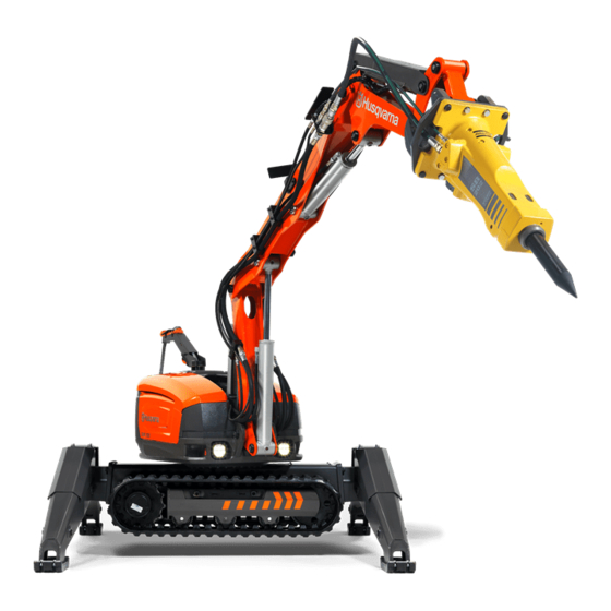
PRESENTATION What is what on the machine? 1 Emergency stop 21 Cable arm 2 Hydraulic tank 22 Warning light Lubrication pump for lubricating the hammer 23 Communication cable socket 4 Arm 1 24 Horn 5 Arm 2 25 Base plate 6 Arm 3 26 Lifting eye bolts 7 Cylinders... -
Page 8: Hydraulic System
HYDRAULIC SYSTEM General The task of the hydraulic system is to operate the machine’s functions by means of hydraulic pressure and flow. The system consists of hydraulic pump, tank, cooler, hydraulic motor, hydraulic cylinders, filters and valves of various kinds. Hoses or pipes connect the components with each other. -
Page 9: Hydraulic System
HYDRAULIC SYSTEM The machine’s hydraulic system 1 Air filter 14 Valve - release track tension 2 Lever indicator 15 Accumulator - track tension 3 Oil filter 16 Drive motor 4 Hydraulic tank 17 Support wheel 5 Cylinder 1 18 Cylinders for track tensioning 6 Cylinder 4 19 Tensioning wheel 7 Cylinder 3... -
Page 10: Electrical System
ELECTRICAL SYSTEM General The electric system consists of a high-voltage circuit and a low-voltage circuit. High-voltage circuit High-voltage is used as a power source for both the electric motor and the low-voltage circuit. An automatic phase rotation change-over switch ensures that the electric motor has the correct rotation direction. -
Page 11: Electrical System
ELECTRICAL SYSTEM The machine’s electric system 1 Aerial 8 Control module 2 Electrical cabinet 9 Radio module 3 Pressure switch 10 Working lights 4 Temperature sensor 11 Pressure sensor 5 Warning light 12 Main switch 6 Power cable 13 Emergency stop 7 Electric motor –... -
Page 12: Control System
CONTROL SYSTEM General Battery The remote control, the electronics unit and the pilot control The battery is a Li-ion type. Operating time is about 8-10 valves are the main components in the control system. The hours per charge. Extreme cold impairs the battery’s capacity signals from the remote control are transmitted to the and operating time. -
Page 13: Control System
CONTROL SYSTEM What is what on the remote control? 1 Left joystick 9 Pressure/flow to hydraulic tool (hammer/cutter) 2 Left joystick - left button 10 Flow to machine movement/speed 3 Left joystick - right button 11 Stop button motor 4 Menu buttons 12 Main switch 5 Display 13 Machine stop... -
Page 14: Control System
CONTROL SYSTEM Symbols on the remote control 1 Arm 2 down 16 Rear/front left outrigger down 2 Right caterpillar track forward 17 Rotate tower anticlockwise 3 Arm 1 and arm 2 out 18 Left outrigger down 4 Angle tool outwards 19 Caterpillar tracks forward 5 Right outrigger down 20 Left caterpillar track forward... -
Page 15: Machine´s Safety Equipment
MACHINE´S SAFETY EQUIPMENT General Identity code The remote control and the machine are connected by means In this section the machine’s safety features and their function of a pre-programmed ID code. The ID code ensures that the are explained. Concerning inspection and maintenance, see right remote control is used for the right machine. - Page 16 MACHINE´S SAFETY EQUIPMENT Mechanical protection Automatic phase rotation relay The automatic phase rotation relay prevents the electric motor starting with the wrong rotation direction thus causing mechanical damage. Motor protection To prevent overloading, the motor is equipped with bimetallic relays in the motor linings that disconnect the power to the motor if it gets too hot.
-
Page 17: Safety Instructions
Use the safety instructions as guidelines and support so that you can detect possible risks yourself and take measures to prevent them. Let your Husqvarna dealer regularly check the machine and make essential adjustments and repairs. – 17 English... -
Page 18: General Working Instructions
Put measures in place to prevent future accidents. and the like, increase the size of the risk area. Define and • Always notify Husqvarna Construction Products in the cordon off the risk area at ground level and ensure that no event of near-accidents or accidents regardless of material can fall down and cause injury. - Page 19 SAFETY INSTRUCTIONS Personal safety Operation General WARNING! This machine produces an • Only authorized and trained operators are permitted to electromagnetic field during operation. This operate the machine and its tools. field may under some circumstances interfere with active or passive medical •...
- Page 20 SAFETY INSTRUCTIONS Manoeuvring • When the arm system’s reach is being used, the load increases as does the risk of tipping. Position the machine General as close to the working object as possible. • If several machines are used at the same workplace there •...
- Page 21 SAFETY INSTRUCTIONS Uneven surfaces Falling material • Extend the outriggers so that they are positioned just • Watch out for demolition material becoming loose when above the surface when moving over uneven areas. cutting. Use personal safety equipment and keep your distance.
- Page 22 SAFETY INSTRUCTIONS Maintenance and service The machine’s position on the loading platform • Position the machine against the front edge of the Most accidents involving machines occur during trouble platform in order to reduce the risk of it sliding forward if shooting, service and maintenance as staff have to locate the vehicle brakes.
-
Page 23: External Environmental Factors
SAFETY INSTRUCTIONS External environmental factors Cold Do not use maximum pump pressure if the hydraulic fluid is Temperature less than 10°C (50°F). Allow the machine to warm up slowly. Warm up the lower section by running the caterpillar tracks, The ambient temperature, both heat and cold, affects the first slowly and then more quickly with the outriggers machine’s operational reliability. -
Page 24: Starting And Stopping
STARTING AND STOPPING Before starting Starting the electric motor • The electric motor is started by pressing the start button. The following points should be checked when working at a new site and every morning before starting: • Carrying out daily inspections. •... -
Page 25: Operation
OPERATION Operating modes The machine can be operated in three different modes: work mode, set-up mode and transport mode. All commands in each of the modes are described in this section. • Work mode - In this mode you can operate everything except the caterpillar tracks and outriggers. •... - Page 26 OPERATION Work mode Extra function For activation, see instructions in the 'Settings' section under Rotate tower the heading 'Extra features'. anticlockwise Extra 1, direction 1 Rotate tower clockwise Extra 1, direction 2 Arm 1 in Extra 2, direction 1 Arm 1 out Extra 2, direction 2 Arm 2 down Arm 2 up...
- Page 27 OPERATION Set-up mode Transport mode Track operation Right track forward left track backward Right caterpillar track forward Right track backwards, left track forward Right caterpillar track backwards Rotate tower clockwise Left caterpillar track forward Rotate tower anticlockwise Left caterpillar track backwards Caterpillar tracks Outriggers forward...
-
Page 28: Tools
'Control system” section. The machine can be used with the following tools or accessories marketed by Husqvarna Bucket 85 L The bucket is designed to move material. It is not designed for use as a lifting implement. -
Page 29: Changing Tools
TOOLS Changing tools • Shut off the machine. • Insert the wedge so that the holes for the locking pin fit. CAUTION! Changing tools may mean that • Insert the locking pin. the operator has to be within the machine’s risk area. -
Page 30: Settings
SETTINGS Track widener The machine is equipped with track wideners for increased stability when working with the machine. • Width with track widener: 1110 mm (44 in) • Width without track widener: 780 mm (31 in) Assembly • Extend the outriggers. •... -
Page 31: Menu Overview
SETTINGS Menu overview Display texts are illustrated in English in the manual but will appear in the chosen language on the product display. Operational settings WORK BREAKER WORK BREAKER Select this when you want to work with a breaker. Press the selection key to confirm the choice. CRUSHER WORK CRUSHER... -
Page 32: Service
SETTINGS ADJUSTABLE Adjustable tool Adjustable tool Oil press. A-B: 200 bar WORK Oil flow A-B: 50 l/min (30...250 bar) ADJUSTABLE (5...65 l/min) Adjustable tool Adjustable tool Oil press. B-A: 150 bar Oil flow B-A: 50 l/min (30...250 bar) (5...65 l/min) Adjustable tool Oil DIRECTION A<=>B Back... -
Page 33: Hour Meter
SETTINGS EXTRA FUNCTIONS (optional) Extra function1 Oil pressure A-B 200 bar (30... 250 bar) Extra function1 Oil pressure B-A 200 bar (30... 250 bar) The machine can be equipped with extra valves to make it capable of running more functions, such as a rotor and a tilt. The value for oil pressure and oil flow can be adjusted from port A to B. - Page 34 SETTINGS WARNINGS Warning log machine Active warnings SERVICE WARNINGS Warning log terminal Back The machine has 2 warning logs and a list of active warnings. • Warning log machine: Records all warnings that have been present in the machine. All active warnings and service messages are listed after they have been confirmed.
- Page 35 SETTINGS TUNING Enter code Hydraulics Joystick SERVICE _ _ _ _ _ _ TUNING Machine type Mating Bluetooth® radio modules Languages Units Back Terminal Diagnostics Back Enter the 6 digit code to proceed to settings. Hydraulics Languages The following components can be adjusted: Setting for which language should be shown in the display.
-
Page 36: Maintenance And Service
MAINTENANCE AND SERVICE General Working environment • The area around the machine must be free of dirt in order to minimize the risk of slipping. WARNING! Most accidents involving machines occur during trouble shooting, • Clean the machine. Dirt in the hydraulic system leads service and maintenance as staff have to rapidly to consequential damage and stoppages. -
Page 37: Cleaning
MAINTENANCE AND SERVICE Cleaning • Keep a distance of at least 40 cm between the cooler and the nozzle. Electrical components CAUTION! Turn off the motor. Disconnect the power cable and place it so that it cannot be Clean electric motor, electric cabinet, terminals and other connected by mistake. -
Page 38: Service Schedule
MAINTENANCE AND SERVICE Service schedule The service schedule is based on the machine’s operating time. More frequent service intervals might be necessary when working in dusty or hot environments and in conjunction with work that generates high temperatures. A description of how the operations are to be performed is to be found in the service review. - Page 39 MAINTENANCE AND SERVICE Weekly service Carry out a daily inspection as per the service schedule before you carry out the weekly service. Lubrication Cylinders and shafts in lower part and outriggers Grease nipples (29) Gear ring Cracks Arm system Mountings Bolt fasteners, shafts, support leg bracket and track sides Drive, track sides and track tensioning Power unit (motor, fan)
- Page 40 MAINTENANCE AND SERVICE After the first 100 hours Change After the first 100 hours the following maintenance should be carried out, subsequently every 1,000 hours. Oil gearbox slew motor Contact your service agent. Oil gearbox drive motor Contact your service agent. 250 hours service Carry out the weekly service as per the service schedule before you perform the 250 hours service.
-
Page 41: Service Review
MAINTENANCE AND SERVICE Service review Gear ring The gear ring has separate grease nipples for bearings and cogs. To ensure that the grease is evenly distributed it should WARNING! Ensure that nobody starts the be applied followed by rotation and then applied again. machine by mistake. -
Page 42: Mountings
MAINTENANCE AND SERVICE Mountings Tightening torque Use abutment when torquing through shafts to avoid the shaft General rotating. • Check that all components are properly secured by feeling, Position pulling etc. Keep a look out for wear damage. This can be Gear ring bearings against chassis caused by components coming loose. - Page 43 MAINTENANCE AND SERVICE Level check Wear and damage Position the machine on a flat surface. Clean the component before it is opened for reading or filling in order to prevent dirt NOTICE! Deal with worn components as quickly as entering the system. If the oil level is low, refill with the type possible.
- Page 44 MAINTENANCE AND SERVICE Leakage Components that should not be welded The following components should not be repaired but replaced: NOTICE! Leakage can cause serious mechanical breakdowns and an increased risk of slipping. Wash the • Tool attachment machine regularly to increase the chance of detecting •...
- Page 45 MAINTENANCE AND SERVICE Tool attachment Cleaning non-return valves • The non-return valves can be cleaned by discharging the pressure in the accumulator and thus loosening the WARNING! The tool attachment’s cotter and tension of the tracks. pin are important safety components. A worn or damaged cotter must be replaced •...
- Page 46 MAINTENANCE AND SERVICE Hydraulic fluid Replenishing hydraulic fluid The machine is equipped with a refill pump. • Manoeuvre the machine so the arm system’s cylinders CAUTION! Allow the machine to cool. Hot oil are retracted and the outriggers are completely folded. can cause severe burn injuries.
-
Page 47: Troubleshooting
TROUBLESHOOTING Error messages There are two types of error messages that can appear on the display: • Service messages - These messages do not represent any direct danger for the operator or the machine. • Warnings - These warn of faults or safety defects that can cause mechanical damage. All error messages that have been acknowledged remain as small yellow red warning triangles in the field for service and can be accessed by bringing up the service menu and selecting 'Warnings”. - Page 48 TROUBLESHOOTING Warning messages Indication on the Effect on machine Message on the display Cause Possible action machine functions Put the machine into circular pumping mode to cool the hydraulic oil. Oil temperature too high. The oil temperature Clean the cooler Machine speed has been is above 90°C reduced and tool is disabled.
- Page 49 TROUBLESHOOTING Communication error Indication on the Effect on machine Message on the display Cause Possible action machine functions Restart the The PLC module do No secondary control module found in machine. Check No indication on not find any slave machine. Please check control modules supply and CAN machine.
- Page 50 TROUBLESHOOTING Cable/Sensor error Effect on machine Message on the display Indication on the machine Cause Possible action functions The cable has a short Cable to * has faulty circuit. Please circuit or broken check cable. circuit. The function using Check cable. the cable disabled.
-
Page 51: Troubleshooting Schedule
TROUBLESHOOTING Troubleshooting schedule WARNING! Most accidents involving machines occur during trouble shooting, service and maintenance as staff have to locate themselves within the machine’s risk area. Prevent accidents by being alert and by planning and preparing the work. You can also refer to 'Preparations for maintenance and service” in the 'Maintenance and service”... - Page 52 TROUBLESHOOTING Joystick in an operative position when starting the Restart the remote control with the joystick in neutral position. remote control. An individual function is not working. Fault in the pilot control valve or the spool in the Contact your service agent. valve i stuck or damaged.
-
Page 53: Guide Values For Mains Connection
TECHNICAL DATA Guide values for mains connection The power cable must be dimensioned by a qualified person in accordance with national and local regulations. The mains socket to which the machine is connected must be dimensioned for the same amperage as the machine’s electrical socket and extension cable, e.g. -
Page 54: Technical Data
TECHNICAL DATA Technical data General Rotation speed, rpm Transport speed max., km/h / mph 3/1,9 Angle of inclination, max. 30° Hydraulic system Volume hydraulic system, l/gal 50/13 Pump type Load sensing axial piston pump with variable displacement Pump flow max.*, l/min / gal/min 65/17 Electric motor Type... - Page 55 TECHNICAL DATA 4868 (192) – 55 English...
- Page 56 TECHNICAL DATA 2057 (81) 2079 (82) 2442 (96) 1598 (63) 1489 (59) 1993 (78) 2066 (81) 2238 (88) 56 – English...
-
Page 57: Ec Declaration Of Conformity
Husqvarna AB, S-561 82 Huskvarna, Sweden, tel: +46-36-146500, declares under sole responsibility that the demolition robot Husqvarna DXR300 dating from 2013 serial numbers and onward (the year is clearly stated on the type plate, followed by the serial number), complies with the requirements of the COUNCIL’S DIRECTIVE: •... - Page 60 GB - Original instructions 1156172-26 ´®z+X16¶6y¨ ´®z+X16¶6y¨ 2013-09-25...