JVC GY-HM600U Instructions Manual
Hd memory card camera recorder
Hide thumbs
Also See for GY-HM600U:
- Instruction manual (136 pages) ,
- Service manual (26 pages) ,
- Instructions manual (144 pages)
Table of Contents
Advertisement
Quick Links
Download this manual
See also:
Instruction Manual
.
HD MEMORY CARD CAMERA RECORDER
GY-HM600U/GY-HM600E
INSTRUCTIONS
.
The specifications and appearance of this product are subject to changes for further improvement
without prior notice.
Please check the latest version of the INSTRUCTIONS from the following Mobile User Guide, or
download the PDF from the URL below.
Mobile User Guide
When you are outside, you can refer to the instructions from your Android phone or
iPhone.
http://manual3.jvckenwood.com/pro/mobile/global/
You can view the Mobile User Guide using the browser on your Android phone or
iPhone.
For Customer Use:
Enter below the Serial No. which is located
on the body.
Retain this information for future reference.
Model No.
Serial No.
.
IM 6.00
GY-HM600U
Please read the following before getting started:
Thank you for purchasing this JVC product.
Before operating this unit, please read the
instructions carefully to ensure the best
possible performance.
In this manual, each model number is
described without the last letter (U/E) which
means the shipping destination.
(U: for USA and Canada, E: for Europe)
Only "U" models (GY-HM600U) have been
evaluated by UL.
LST1424-001E
Advertisement
Table of Contents

Related Manuals for JVC GY-HM600U


Summary of Contents for JVC GY-HM600U
-
Page 1: Mobile User Guide
You can view the Mobile User Guide using the browser on your Android phone or iPhone. Please read the following before getting started: Thank you for purchasing this JVC product. Before operating this unit, please read the instructions carefully to ensure the best possible performance. -
Page 2: Important Safeguards
FOR USA These are general IMPORTANT SAFEGUARDS and certain items may not apply to all appliances. IMPORTANT SAFEGUARDS Read these instructions. Keep these instructions. Heed all warnings. Follow all instructions. Do not use this apparatus near water. Clean only with dry cloth. Do not block any ventilation openings. -
Page 3: Safety Precautions
RISK OF ELECTRIC undesired operation. SHOCK DO NOT OPEN Changes or modifications not CAUTION: approved by JVC could void the TO REDUCE THE RISK OF user’s authority to operate the ELECTRIC SHOCK. equipment. This equipment has been DO NOT REMOVE COVER (OR tested and found to comply with the BACK). - Page 4 POUR CANADA WARNING: TO PREVENT FIRE OR SHOCK HAZARD, DO NOT EXPOSE THIS UNIT TO RAIN OR ATTENTION MOISTURE. RISQUE D’ELECTROCUTION AVERTISSEMENT : POUR EVITER NE PAS OUVRIR LES RISQUES D’INCENDIE OU ATTENTION: D’ELECTROCUTION, NE PAS POUR EVITER TOUT RISQUE EXPOSER L’APPAREIL A LA D’ELECTROCUTION NE PAS PLUIE NI A L’HUMIDITE.
- Page 5 “Siemens Plug” as shown. When discarding batteries, For this AC plug adapter, consult your environmental problems must be nearest JVC dealer. considered and the local rules or laws Plug Adapter governing the disposal of these batteries must be followed strictly.
- Page 6 FOR EUROPE IMPORTANT (for owners in the This equipment is in conformity with the U.K.) provisions and protection requirements of Connection to the mains supply in the corresponding European Directives. the United Kingdom. This equipment is designed for professional DO NOT cut off the mains plug video appliances and can be used in the from this equipment.
- Page 7 European representative of Terminals To avoid hazards JVC KENWOOD Corporation is: ... do not burn. JVC Technical Services Europe GmbH ... do not short-circuit the Postfach 10 05 04 terminals. Keep it away 61145 Friedberg from metallic objects Germany when not in use.
-
Page 8: Table Of Contents
Contents Para Brasil Informação sobre eliminação de Introduction baterias Safety Precautions ..........3 Este produto não deverá ser eliminado Contents ............8 como lixo doméstico em geral. Main Features ..........10 Devolva a bateria velha ao comerciante Precautions for Proper Use ......12 ou para a rede autorizada, para que seja Operation Modes .......... - Page 9 Adjusting the Focusing by Face Detection ..50 White Balance Item ........101 Adjusting the Brightness ........51 TC/UB Menu ..........102 Adjusting the Iris ..........52 LCD/VF Menu ..........103 Setting the Gain ..........53 Shooting Assist Item ........104 Setting the Electronic Shutter ......
-
Page 10: Main Features
SDI/HDMI Simultaneous Output Equipped with both [HD/SD SDI] and [HDMI] JVC’s Proprietary FALCONBRID High- terminals as digital output. Quality Imaging Engine Non-compressed full HD video signals and audio... - Page 11 The disc provided with this camera recorder companies. Marks such as ™ and ® have comes with [JVC ProHD Clip Manager] and other been omitted in this manual. application software as well as their user guides.
-
Page 12: Precautions For Proper Use
Precautions for Proper Transportation Do not drop or hit this unit against a hard object when transporting. Power Saving Storage and Usage Locations When this unit is not in use, be sure to set the o Allowable ambient temperature and humidity [POWER ON/OFF(CHG)] switch to “OFF(CHG)”... - Page 13 o We are not liable for any accidental loss of data Regular Inspection (Maintenance) stored on the SD card. Please back up any Under normal environment, dust will accumulate important data. on the camera recorder when it is used over a long o Make use of the SD card within the prescribed period.
-
Page 14: Lcd Monitor And Viewfinder
Others LCD Monitor and Viewfinder o Do not insert objects other than the memory card o The LCD monitor and viewfinder screen are into the card slot. manufactured using high-precision technology. o Do not block the vent on the unit. Black spots may appear on the LCD monitor and viewfinder screen, or red, blue, and/or white spots Blocking of the vent causes internal heating and... - Page 15 License Notices o MPEG LA AVC THIS PRODUCT IS LICENSED UNDER THE AVC PATENT PORTFOLIO LICENSE FOR THE PERSONAL USE OF A CONSUMER OR OTHER USES IN WHICH IT DOES NOT RECEIVE REMUNERATION TO (i) ENCODE VIDEO IN COMPLIANCE WITH THE AVC STANDARD (“AVC VIDEO”) AND/OR (ii) DECODE AVC VIDEO THAT WAS ENCODED BY A CONSUMER ENGAGED IN A PERSONAL ACTIVITY AND/OR...
-
Page 16: Operation Modes
Operation Modes This camera recorder has three operation modes - Camera mode, Media mode, and USB mode. Media Mode [MODE] Button Camera Mode Playback Playback Button (Playback/Pause/ Thumbnail Frame-by-Frame/ Display Press and hold Fast Forward/Rewind/ Stop [MODE] button Clip Jump) Button USB Connection (When the confirmation to change to... - Page 17 Operation Mode Description Camera Mode This is the camera shooting mode. The camera recorder starts up in Camera mode when the power is turned on. Camera images are output on the viewfinder and LCD monitor. When a recordable SD card is inserted, the camera recorder enters the recording standby mode. “STBY”...
-
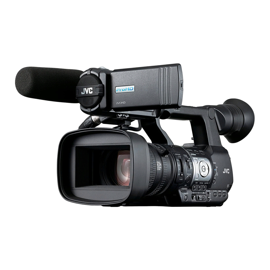
Page 18: Names Of Parts
Names of Parts Bottom ZOOM SERVO MANUAL A Built-in Microphone J [ZOOM SERVO/MANUAL] Zoom Operation (A P61 [Audio Recording] ) Servo/Manual Switch Set to “SERVO” when using the zoom lever at B Tally Lamp the grip j or the zoom lever at the handle a. (A P36 [Tally Lamp] ) (A P46 [Zoom Operation] ) (A P137 [Blinking of the Tally Lamp] ) - Page 19 HOLD IN OUT R S T R [REC] Record Trigger Button Y [INPUT1/INPUT2] Audio Input Terminal 1, 2 Starts/stops recording. (XLR 3-pin x 2) (A P25 [Attaching an External Microphone] ) Memo : Z [REC/HOLD] Record Trigger Button/Lock This button is interlocked with the [REC] button Switch I at the bottom of the lens and the [REC/ Starts/stops recording.
-
Page 20: Side Control Panel
Side Control Panel L [ZEBRA/5] Zebra/User 5 Button (A P69 [Setting Zebra Pattern] ) You can also use it as a user button by assigning S R Q a specific feature in the menu setting to this button. (A P36 [Assignment of Functions to User FOCUS ASSIST/1 OIS / 2 LOLUX / 3... -
Page 21: Sd Slot
Rear Terminal R [OIS/2] Optical Image Stabilizer/User 2 Button For switching the image stabilizer feature mode ON or OFF. You can also use it as a user button by assigning a specific feature in the menu setting to this button. (A P36 [Assignment of Functions to User Buttons] ) S [FOCUS ASSIST/1] Focus Assist/User 1 Button... -
Page 22: Lcd Monitor
LCD Monitor F [LCD BRIGHT +/-] LCD Display Brightness Adjustment Button (A P34 [Adjusting the Brightness] ) G [PEAKING +/-] LCD/VF Contour Adjustment Button (A P35 [Adjusting the Contour (LCD)] ) (A P35 [Adjusting the Contour (Viewfinder)] ) H [DISPLAY] Display Button MENU/THUMB Press the [DISPLAY] button to switch to the INPUT1... -
Page 23: Lens Section
Lens Section A Filter Built-In Screw Transparent or UV filter for lens protection, or filters for various effects can be installed. Installable filter types: Φ72mmP0.75 Memo : Remove the lens hood when installing the filter. (A P26 [Attaching/Detaching the Hood] ) B Lens Cover Open/Close Switch (A P26 [Opening/Closing the Lens Cover] ) C Focus Ring... -
Page 24: Basic System Diagram
Basic System Diagram GY-HM600 Shoulder Belt Monitor Earphone Wireless Microphone Receiver Microphone [TC] [AUX] Monitor SDI Cable GY-HM600 HDMI Cable AV Cable RCA pin Battery AC Adapter Remote Control Unit Carrying Case USB Cable Tripod Non-linear Editing SDHC/SDXC SDHC/SDXC System Memory Card Card Reader... -
Page 25: Settings And Adjustments Before Use
Settings and Adjustments Attaching the Tripod Before Use Use the screw hole at the bottom of this camera recorder. (3/8×16UNC, 1/4×20UNC) Use the screw hole that suits the tripod. To prevent the camera recorder from falling off, Adjusting the Grip Belt which may result in injuries or damages, read the Open the pad and adjust the position of the grip belt instruction manual of the tripod to be used and... -
Page 26: Opening/Closing The Lens Cover
Detaching the Hood Opening/Closing the Lens Cover Remove the hood when attaching a filter, Use the lens cover open/close switch to open or teleconverter or wide converter to the front of the close the lens cover. lens. Before shooting, open the lens cover. While pressing the hood release button, turn the When this camera recorder is not in use, close the hood in the anti-clockwise direction to remove it. - Page 27 LCD monitor is frequently used. (CHG) For purchase of spare batteries and battery MODE charger, consult your nearest JVC dealer. 1 Hold down the lock button (blue) at the Precautions for Batteries center of the [POWER ON/OFF(CHG)] switch to set to “OFF(CHG)”.
-
Page 28: Using Ac Power (Dc In Power)
Power Status Display Using AC Power (DC IN Power) Use the supplied AC adapter to operate the camera recorder with AC power. Viewfinder Screen and LCD Monitor The power status is displayed on the display and menu screens. Display Description B 7.4V Currently powered by a battery. -
Page 29: Turning On/Off The Power
Warnings by Lamp and Warning Tone Turning Off the Power Warning status is indicated by tally lamp and Sets the camera recorder to the recording standby warning tone. or stop mode. The tally lamp blinks. 1 Hold down the lock button (blue) at the The warning tone is output from the monitor center of the [POWER ON/OFF(CHG)] switch speaker or [x] terminal. -
Page 30: Initial Settings
Initial Settings Memo : The menus and messages on the screen of the When the power is first turned on, the Initial Setting LCD monitor or viewfinder are displayed in the screen for performing the initial settings in the selected language. camera recorder appears. - Page 31 Changing the Time after Initial Setting 4 Press the Set button (R) after confirming the exit screen. Setting the Date/Time The [Initial Setting] screen appears. (A P111 [ Date/Time ] ) For U models 1 Select [System] B [Date/Time]. The [Date/Time] screen appears. 2 Set the date and time.
-
Page 32: Displays On The Lcd Monitor And Viewfinder
Displays on the LCD Display Screen (VF/LCD) in Media Mode (A P124 [Display Screen in Media Mode] ) Monitor and Viewfinder This is the screen display during clip playback in Media Mode. The display switches between three screen You can display the camera status, media types with every press of the [DISPLAY] button. -
Page 33: Status Screen
Status Screen USB Mode Screen This screen allows you to check the current This screen displays the USB mode. settings. To display the status screen, press the [STATUS] button in the normal screen. The status display differs according to the operation mode (two types). -
Page 34: Adjusting The Lcd Monitor And Viewfinder
Adjusting the LCD Monitor Adjusting the LCD Monitor and Viewfinder LCD BRIGHT PEAKING You can monitor video images on this camera Tilt 90 degrees recorder using the viewfinder, LCD monitor, or downward both. Normal LCD Inverted DISPLAY Tilt 180 degrees upward 1 Open the LCD cover. -
Page 35: Adjusting The Viewfinder
Caution : Adjusting the Contour A high-definition viewfinder is used on this Use the [PEAKING +/-] button to adjust the camera recorder in order to provide an accurate contour of the LCD monitor. focusing environment. Due to the characteristic (The contour of the viewfinder screen will also of the display device, colors may appear on the be adjusted at the same time.) images when you blink your eyes. -
Page 36: Assignment Of Functions To User Buttons
Displaying in Black and White 1 Assign functions to the buttons from the menu. You can display the viewfinder screen in black Set items in [Main Menu] B [Camera and white. Function] B [User Switch Set] B [USER1]- [Main Menu] B [LCD/VF] B [VF Color] item [USER7], [LCD KEY▲], [LCD KEY▶], [LCD B Press Set button (R) B Select “Off”... -
Page 37: Sd Card
SD Card QuickTime H.264/HD H.264/SD This camera recorder saves the recorded images 1080i/1080p 480i/576i and audio sound on the SD card (sold separately) 4 GB in the card slot. 8 GB 16 GB Usable Cards 32 GB Use a Class 6/10 SD card. 64 GB (SDXC) Memo :... - Page 38 Inserting an SD Card Removing the SD Card This camera recorder comes with two card slots 1 Check that the SD card to be removed is not (Slot A and B) for video/audio recording and being accessed (status indicator of the playback.
-
Page 39: Formatting (Initializing) Sd Cards
Switching the SD cards 1 Select [System] B [Media] B [Format When both card slots are inserted with SD cards, Media]. you can use the [SLOT A/B] button to switch the (A P110 [ Format Media ] ) card to use. 2 Select the slot of the SD card to be When the memory on an SD card is full during formatted and press the Set button (R). -
Page 40: Restoring The Sd Card
6 Formatting is complete. 3 Restoring starts. When formatting is complete, “Complete” appears and the camera recorder returns to the [Format Media] screen. Memo : During formatting, menu operation is unavailable but you can start recording. However, this is only available when a recordable SD card is inserted in the other slot. -
Page 41: Clips Recorded To Sd Cards
Clip (Recorded Data) and Clip Name When copying videos in MP4 file format to a HDD using a PC, it is recommended to use [JVC When recording is stopped, the images, audio ProHD Clip Manager Software], which is found and accompanying data which are recorded from start to stop are recorded as one “clip”... -
Page 42: Operation Lock Feature
Operation Lock Feature Operation lock does not apply to the following buttons and switches. [POWER ON/OFF(CHG)] switch You can use this feature to prevent erroneous [ND FILTER] switch camera operation. TC [IN/OUT] selection switch All switches inside the LCD monitor door (however, the operation of the [CH1/CH2] MENU/THUMB adjustment knob will be locked.) -
Page 43: Shooting
Basic Shooting 2 Press the [REC] button to start recording to Procedures the SD card. This camera recorder has three [REC] buttons. Any of the [REC] buttons can be used to start/ Preparations stop recording by default. The tally lamp lights up in red during recording. Zoom Operation (A P46 [Zoom Operation] ) Adjusting the Focus Manually... -
Page 44: Selecting System Definition, File Format And Video Format
Selecting System Selecting a File Format Definition, File Format and Select a file format in [Format]. There are four file formats for selection. Video Format QuickTime(MPEG2): QuickTime file format (.MOV) MP4(MPEG2): You can select the system definition (HD or SD), MP4 file format file format for recording/playback and the record AVCHD:... - Page 45 List of Formats When [System] is set to “SD” When [System] is set to “SD”, the video format is The following is a list of file formats and video fixed as follows for the different models. formats that can be selected on this camera recorder.
-
Page 46: Zoom Operation
Zoom Operation Using the Zoom Lever at the Grip 1 Set the [ZOOM SERVO/MANUAL] switch to Adjusts the angle of view. “SERVO”. Zoom ratio: 1x to 23x (optical zoom only) 2 Press the zoom lever to zoom. Zooming can be operated using any of the three The zoom speed changes according to the levers/rings below. -
Page 47: Focus Operation
Focus Operation Using Zoom Ring at the Lens Section 1 Set the [ZOOM SERVO/MANUAL] switch to “MANUAL”. Adjusting Focus Manually You can adjust the preferred angle of view by turning the zoom ring. Saving/Recalling Current Zoom Position (Preset Zoom) FOCUS This allows you to register up to three zoom FOCUS ASSIST/1 AUTO... - Page 48 Adjusting Focus Automatically AF Assist Function Set the [FOCUS AUTO/MANU/∞] switch to To shift the auto focus point during Auto Focus (AF), you can turn the focus ring to set the point to “AUTO”. the left, center, right, or near and far directions. The auto focus icon e appears on the screen.
-
Page 49: Focus Assist Function
Focus Assist Function Expanded Focus Function When the [FOCUS ASSIST/1] button is pressed Magnifies the image at the center. Doing so enables precise focus to be established easily. during shooting, the focused area is displayed in color. This enables easy and accurate 1 Assign the “Expanded Focus”... -
Page 50: Adjusting The Focusing By Face Detection
Adjusting the Focusing by 1 Assign the “Face Detect” function to any of Face Detection the user buttons. (A P36 [Assignment of Functions to User Buttons] ) This function detects human faces and 2 Focus the camera recorder on a person and automatically adjusts focus during Auto Focus. -
Page 51: Adjusting The Brightness
Adjusting the Brightness Selecting Specific Person from Several Persons 1 Hold down the user button that is assigned Adjust the brightness using Iris, Gain, Shutter with “Face Detect”. speed and ND filter according to the brightness of the object. The camera recorder will enter face selection mode and the face detection icon Adjusting the Brightness Automatically (q) will blink. -
Page 52: Adjusting The Iris
Adjusting the Iris Auto Iris (Automatic Adjustment) Mode Press the [IRIS] button to set to the Auto Iris mode. The iris is automatically adjusted according to the You can adjust the aperture of the lens iris manually brightness of the object. or automatically according to the brightness of the The a icon appears on the screen. -
Page 53: Setting The Gain
Setting the Gain Automatic Gain Mode (Automatic Gain Adjustment) This function electrically boosts the light sensitivity 1 Set the [FULL AUTO] switch to “ON”. when there is insufficient illumination on the object. The a icon appears on the screen. You can set the gain of the video amplifier Memo : according to the brightness of the object. -
Page 54: Setting The Electronic Shutter
Setting the Electronic Switching Shutter Speed When shutter is ON, use the cross-shaped button Shutter (JK) to set the shutter speed. Shutter speed differs according to the video format and variable frame rate settings. You can change the shutter speed (time for each shooting frame) using the electronic shutter Memo : function. - Page 55 During Variable Frame Rec Resolution/ 720/30p, 720/24p, 1080/30p, 1080/24p Shutter Frame & Bit Rate 60, 30, 15 54, 27 50, 25 48, 24, 12, 6 45, 22.5 40, 20, 10 36, 18 32, 2 Frame Rate 1/10000 1/10000 1/4000 (Step) 1/10000 1/4000 1/2000...
-
Page 56: Setting The Nd Filter
Automatic Shutter Mode (Automatic Shutter Adjustment) 00: 00: 00.00 1 Press the [SHUTTER] button or set the Jan 24 ,2012 12 :34 : 56 [FULL AUTO] switch to “ON” to enter ND 1 /64 Automatic Shutter mode. 5 . 6f t ND 1 /64 The a icon appears on the screen. -
Page 57: Adjusting The White Balance
Adjusting the White Preset Mode (PRESET) Balance Two different color temperature settings are registered on this camera recorder. You can switch between them using the [y] button. (Default setting: “3200K” 1 “5600K”) Adjust the white balance according to the color temperature of the lighting. - Page 58 Memo : Use the cross-shaped button (I) to switch 282min 00: 00: 00.00 between the Color Temperature Selection 100min 50min screen and the Color Temperature Detailed Jan 24,2012 12 :34 :56 Selection screen. 1920x1080 White Detection If [White Balance] has been assigned to the user 60 i 5 .
- Page 59 White Paint Adjustment Automatic White Balance Mode (FAW: Fulltime Auto White balance) You can fine-tune the white balance saved in Memory A or Memory B. Press the [WHT BAL] button on the side control panel to enter into Automatic White Balance 1 Select [Main Menu] B [Camera Process] B mode.
-
Page 60: Adjusting The Camera Image
Adjusting the Camera FAW Paint Adjustment You can fine-adjust the white balance that was Image automatically adjusted. 1 Select [Main Menu] B [Camera Process] B The picture quality of the camera can be set using [White Balance] B [FAW Paint] and press the [Camera Process] menu. -
Page 61: Using The Image Stabilizer
Using the Image Stabilizer Audio Recording Reduces blurring of images due to camera shake. You can record audio from the two channels (CH1/ CH2) in synchronization with video images on this 1 Check whether the image stabilizer feature camera recorder. is turned ON or OFF. -
Page 62: Adjusting Audio Recording Level
Setting Input Channel to [INPUT1]/[INPUT2] Adjusting Audio Recording Level Select the audio to input to [INPUT1] and [INPUT2] You can select to adjust the audio recording levels terminals with the [INPUT1]/[INPUT2] mode for the two channels (CH1/CH2) manually or automatically. switch. -
Page 63: Monitoring Audio Sound During Recording Using A Headphone
Monitoring Audio Sound o Setting Input Channel to “INT” for Both [CH1] and [CH2] During Recording Using a 1 Set the [CH1 AUTO/MANUAL] selection Headphone switch to “MANUAL”. 2 Turn the [CH1] recording level adjustment You can check the recorded audio using knob to adjust the level. -
Page 64: Time Code And User's Bit
Time Code and User’s Bit Time Code Operation Mode Set the time code operation in [Main Menu] B [TC/ UB] B [TC Generator]. Time code and user’s bit data are recorded with the (A P102 [ TC Generator ] ) video in this camera recorder. -
Page 65: Setting Time Code Generator
Setting Time Code 2 Select the framing mode for the time code Generator generator (only when the frame rate setting is “60” or “30”). Set using [Main Menu] B [TC/UB] B [Drop Presetting the Time Code Frame]. (A P103 [ Drop Frame ] ) Time code and user’s bit data generated from the [Drop]: internal time code generator are recorded. - Page 66 Setting Time Code without Opening the 1 Select [Main Menu] B [TC/UB] B [TC Menu Preset] and press the Set button (R). (A P102 [ TC Preset ] ) The [TC Preset] screen appears. MENU/THUMB CANCEL MENU/THUMB AE LEVEL FOCUS ASSIST/1 OIS / 2 Memo : CANCEL...
-
Page 67: Setting The User's Bit
Setting the User’s Bit 4 Check the values and press the Set button (R). The time code is set and the screen returns You can add the date, time or an 8-digit to the normal screen. hexadecimal number as the user’s bit to the To cancel the setting, press the [CANCEL] recorded image. -
Page 68: Synchronizing Time Code On Another Camera
Synchronizing Time Code 1 Set [Main Menu] B [TC/UB] B [UB Mode] to on Another Camera “Preset”, and press the Set button (R). (A P102 [ UB Mode ] ) The [UB Mode] setting screen appears. This camera recorder is equipped with a time code input/output terminal ([TC] terminal). -
Page 69: Setting Zebra Pattern
Setting Zebra Pattern Settings and Operation of the Camera Recorder 1 Set to Camera mode. When the luminance level range for displaying (A P16 [Operation Modes] ) zebra patterns is specified, diagonal lines (zebra pattern) are displayed at areas with the specified 2 Set [TC/UB] B [TC Generator] as follows. -
Page 70: Setting Spot Meter
Setting Spot Meter Color of Frame Item Settings Indicating the The brightness of the object during shooting is Position displayed. Max & Min Displays the Max: Green This function is useful when setting video or stage brightness (%) Min: Yellow lighting or when specifying camera exposure. - Page 71 When [Max & Min]/[Max]/[Min] is selected When [Manual] is selected A The cursors appear according to the setting A The brightness of the cursor position is when the button is pressed. displayed when the button is pressed. Green and yellow frames appear, and the brightness levels of these areas are displayed.
-
Page 72: Viewing Recorded Videos Immediately (Clip Review)
Viewing Recorded Videos Caution : During Clip Review, only the [CANCEL] and Immediately (Clip Review) [REC] buttons are enabled. Press the [CANCEL] button to cancel clip review You can check (review) the last recorded video clip and return to “STBY” (recording standby) mode. on the screen. -
Page 73: Splitting The Clips Freely (Clip Cutter Trig)
Splitting the Clips Freely Dual Rec (Clip Cutter Trig) If both the slots are loaded with recordable cards in the factory default ([Slot Mode] is set to You can split the clips freely without having to stop “Series”), pressing the [REC] button starts recording during shooting. -
Page 74: Start Recording
Caution : 2 Start recording. To perform recording in the Dual Rec mode, it is Insert recordable media in both slots, and recommended that you start recording by press the [REC] button. making use of two cards with the same capacity In the Dual Rec mode, recording to the media and from the formatted state. -
Page 75: Backup Rec
Backup Rec 1 Set [Main Menu] B [System] B [Record Set] B [Slot Mode] to “Backup”. (A P113 [ Slot Mode ] ) The Backup Rec mode allows you to make use “BACKUP” appears on the display screen. of the media in slot B for backup recording by controlling the starting and stopping of recording in slot B without using the [REC] button. - Page 76 3 Start normal recording (normal recording 5 Stop backup recording. into slot A) Select [STBY] in [Main Menu] B [System] B Press any of the [REC] buttons. [Record Set] B [Slot Mode] B [Backup Recording into the media in slot A starts. Rec] and press the Set button (R).
-
Page 77: Special Recording
Special Recording 1 Set [Rec Mode] to “Pre Rec”. (A P113 [ Rec Mode ] ) Set [Main Menu] B [System] B [Record Besides the normal recording mode, five special Set] B [Rec Mode] to “Pre Rec”. recording methods are available in this camera recorder. - Page 78 5 Pause recording. Press the [REC] button again to pause Press [REC] Press [REC] Press [REC] (Recording starts) (Recording resumes) (Recording resumes) recording. The display changes (“RRECC” B “STBYC” (yellow text)). Press [REC] Press [REC] Press and hold [REC] The card slot status indicator remains lighted (Recording pauses) (Recording pauses) (Recording stops)
-
Page 79: Frame Rec
Caution : 1 Set [Rec Mode] to “Frame Rec”. If the power is cut off due to low battery power, Set [Main Menu] B [System] B [Record a proper clip may not be generated. Set] B [Rec Mode] to “Frame Rec”. When [Format] in the [Main Menu] B (A P113 [ Rec Mode ] ) [System] B [Record Set] B [Record Format]... -
Page 80: Interval Rec
Interval Rec 3 Set the time interval to start recording in [Interval Rec]. In normal recording, when the recording stops, the image and accompanying data from the start till the Set using [Main Menu] B [System] B [Record end of the recording are recorded as one “clip” on Set] B [Rec Mode] B [Rec Interval]. -
Page 81: Variable Frame Rec
Variable Frame Rec Memo : When [Main Menu] B [Camera Function] B [AE Shooting in this mode allows you to obtain smooth LEVEL SW] is set to “AE LEVEL/VFR”, you can slow motion or quick motion videos. Using different frame rate settings for recording use the cross-shaped button (HI) to select the and playback, videos captured at normal speed frame rate during Variable Frame Rec. -
Page 82: Playing Recorded Clips
Playing Recorded Clips F [OIS/2] Button Switches the selection status of the clip selected by the cursor. To play back clips recorded on SD cards, switch to Clips being selected are displayed with the Media mode. check mark. Press and hold the [MODE] selection button in G [LOLUX/3] Button Camera mode to enter Media mode. - Page 83 Memo : Memo : Depends on the [Main Menu] B [System] B Clips appended with OK marks cannot be [Record Set] B [Record Format] B [System], deleted on the camera recorder. [Resolution] and [Frame & Bit Rate] settings. When [Main Menu] B [System] B [Record (A P112 [ System ] ) Set] B [Record Format] B [Format] is set to (A P112 [ Frame &...
-
Page 84: Actions
Detailed screen Item Description * Items that are common with the Standard screen Add OK Mark Appends an OK mark. will not be described. Refer to “[Standard This Clip: screen] P 82”. Appends an OK mark to the clip pointed by the cursor. Selected Clips: Appends an OK mark to the clips selected (appended... -
Page 85: Playing Back
Time Code Playback Playing back Time code or user’s bit recorded on an SD card can Use the operation buttons on the side control panel be displayed on the LCD monitor and viewfinder. of the camera recorder to play back. Memo : The time code is also superimposed on the video signal output from the [HD/SD SDI] output... -
Page 86: Deleting Clips
Deleting Clips 3 Select [Delete Clips] B [This Clip] and press the Set button (R). A screen to confirm deletion appears. Delete clip. MENU/THUMB CANCEL 4 Select [Delete] using the cross-shaped MENU/THUMB AE LEVEL button (JK), and press the Set button (R). Deleting starts. -
Page 87: Appending/Deleting Ok Mark
Appending/Deleting OK During Playback or Pause Screen Mark 1 Press [FOCUS ASSIST/1] button during clip playback. If the clip does not have an OK mark, an OK mark will be appended. You can append OK marks to the clips for If the clip is appended with an OK mark, the important scenes. -
Page 88: Selecting Multiple Clips Randomly
Selecting Multiple Clips Randomly 3 Move the cursor to the beginning (or end) of the range for multiple selection, and 1 Move the cursor to a clip without check press the Set button (R). mark, and press the [OIS/2] button. 4 Move the cursor to the other end of the A green check mark appears on the clip. -
Page 89: Trimming Recorded Clips
Trimming Recorded Clips A Guide Operation guide You can extract (trim) the necessary parts of a clip B Position bar recorded in the SD card. 6 : Current position of the video The trimmed clip is saved as a new file on the same : Position to start trimming (in point) SD card as the original clip. -
Page 90: Basic Operations In Menu Screen
Basic Operations in Menu A [MENU/THUMB] Button Displays the menu screen. The [Main Screen Menu] screen is displayed by default. During normal usage, [Main Menu] is Press the [MENU/THUMB] button on the side displayed if the previous menu operation ended at [Main Menu], and [Favorites control panel of the camera recorder or on the LCD monitor to display the menu screen on the Menu] if the previous menu operation ended... -
Page 91: Display And Description Of The Menu Screen
Changing Setting Values Display and Description of the Menu Screen Selecting Menu Items A Menu Item to Change Menu item to be changed. A list of setting values F appears in a pop-up. B Operation Guide A Cursor Guide for the current operation buttons. Indicates the selected item. -
Page 92: Text Input With Software Keyboard
Text Input with Software Keyboard D Key Cursor Indicates the currently selected character or Use the software keyboard to enter the [Scene item. Use the cross-shaped button (JKHI) to File]/[Picture File] subname and [Clip Name move the cursor. Prefix]. E Confirmation Buttons Select [Set]/[Store] and press the Set button [Scene File]/[Picture File] (R) to confirm the title. -
Page 93: Menu Screen Hierarchical Chart
Menu Screen Hierarchical Chart Main Menu... TC/UB... Camera Function... TC Generator Bars TC Preset UB Mode Flicker Correction Drop Frame Flash Band Correction Shutter LCD/VF... AE Level Shooting Assist... AE Speed Marker Settings... ALC Limit Display Settings... Auto Iris Limit (OPEN) LCD + VF Auto Iris Limit (CLOSE) VF Color... -
Page 94: Camera Function Menu
Camera Function Menu Caution : Flash band correction function is not available in any of the following cases. Menu screen for specifying operation settings When [Rec Mode] is set to “Variable Frame” during shooting. When [Frame & Bit Rate] is set to “24p(HQ)” This item can only be selected in the Camera When in the Automatic Shutter mode or when mode. - Page 95 ALC Limit AE LEVEL SW For setting the maximum gain value of “ALC”, For specifying the operation of the cross-shaped button (HI) on the right side. which electrically boosts the sensitivity level AE LEVEL/VFR: according to the brightness automatically. Sets the number of frames during Variable [Setting Values: 24dB, R18dB, 12dB, 6dB] Frame Rec, and operates as the AE level setting Auto Iris Limit (OPEN)
-
Page 96: User Switch Set Item
User Switch Set Item Clip Review For specifying the operation when any of the USER1 - USER7, LCD KEY▲/LCD KEY▶/LCD [USER1]-[USER7], [LCD KEY▲], [LCD KEY▶], KEY▼/LCD KEY◀ [LCD KEY▼], or [LCD KEY◀] items is set to “Clip Review”. By assigning one of the following functions to each Last 5sec: of the [FOCUS ASSIST/1], [OIS/2], [LOLUX/3], [AE Views about 5 seconds of the clip from the... - Page 97 Face Detect AE Lock For specifying the operation when any of the For specifying the operation when any of the [USER1]-[USER7], [LCD KEY▲], [LCD KEY▶], [USER1]-[USER7], [LCD KEY▲], [LCD KEY▶], [LCD KEY▼], or [LCD KEY◀] items is set to “Face [LCD KEY▼], or [LCD KEY◀] items is set to “AE Detect”.
-
Page 98: Camera Process Menu
Camera Process Menu 9 Stretch Level Stretch amount increases when a larger value is specified. Menu screen for adjusting the quality of camera [Setting Values: 1 to 5 (R 3)] images. Memo : This item cannot be selected in the Media mode. This item is displayed only when [Black Toe] is Detail set to “Stretch”. - Page 99 9 Sensitivity 9 Gamma Level For setting the response speed of the “Knee” This item can be specified separately when [Gamma] is set to “Standard” or “Cinema”. operation when [Knee] is set to “Auto”. Increase the number: Set to “Slow” when shooting an object under a Enhances the gradation of black.
-
Page 100: Detail/Adjust Item
Color Matrix Shooting Mode For setting the color matrix. For switching the settings for image recording on Cinema Subdued: the camera. Sets to a subdued color matrix that is similar to Standard: the screen characteristics of movies. Normal shooting mode. Cinema Vivid: This setting is suitable for shooting low-noise Sets to a vivid color matrix that is similar to the... -
Page 101: White Balance Item
H Frequency Skin Detail For specifying the correction frequency of the For turning On/Off the Skin Detail function, which horizontal contour. Set this according to the object. is used to adjust the contour correction effect of the High: colors captured. Emphasizes the high frequency range. -
Page 102: Tc/Ub Menu
TC/UB Menu AWB Paint For adjusting the R (red)/B (blue) component in the AWB (Auto White Balance) mode. Menu screen for setting time code and user’s bit. For details, refer to “[Adjusting the White This item cannot be selected in the Media mode, Balance] P 57”. -
Page 103: Lcd/Vf Menu
LCD/VF Menu 9 Preset For setting the user’s bit. (Digit by digit) Display : AB CD EF 01 Item for specifying settings related to the LCD (A P67 [Presetting the User’s Bit] ) monitor or viewfinder screen. Memo : This menu screen can be used to specify settings related to the Focus Assist mode, zebra pattern When [UB Mode] is set to “Date”... -
Page 104: Shooting Assist Item
Shooting Assist Item VF Bright For setting the brightness of the viewfinder screen. Focus Assist Increasing the value increases the brightness. For setting whether to add color to the contour of [Setting Values: -10 to +10 (R 0)] the focused image upon switching the image to VF Contrast black-and-white. -
Page 105: Marker Settings Item
Marker Settings Item 9 Aspect Marker For specifying how boundary markers are to be For setting the marker and safety zone, which are used to indicate the parts of an image that are useful in helping you determine the angle of view beyond the range of the aspect ratio selected in for the image according to the shooting purpose. -
Page 106: Display Settings Item
Display Settings Item Media Remain This menu is used to set the displays on the LCD For setting whether to display the remaining space monitor and viewfinder screen. of the recording SD card. [Setting Values: ROn, Off] Zoom Memo : For setting the display method of the zoom When the remaining space warning is position. -
Page 107: A/V Set Menu
A/V Set Menu Date/Time For specifying whether to display the date and time in the display on the LCD monitor and viewfinder Menu screen for video output and audio. screen. [Setting Values: ROn, Off] Video Set... For specifying video output-related settings. Date Style (A P107 [Video Set Item] ) For setting the date display sequence for display... -
Page 108: Audio Set Item
Audio Set Item 9 SDI Rec Trigger For setting whether to superimpose trigger signals Input1 Mic Ref. in tandem with the [HD/SD SDI OUT] terminal as For setting the reference input level when the well as the [REC] button on the camera body. [INPUT1] selection switch is set to “MIC”... - Page 109 AGC Mode Test Tone For setting whether to link the limiter operation of For specifying whether to output the audio test [CH1] and [CH2]. signals (1 kHz) during color bar output. [Setting Values: On, ROff] Select “Link” to link or “Separate” to separate. [Setting Values: Link, RSeparate] INPUT1/2 Wind Cut Memo :...
-
Page 110: System Menu
System Menu Monitor For setting the audio sound of the [x] terminal to stereo or mixed sound when the [MONITOR] This menu screen allows system-related settings. switch on the LCD monitor is set to “BOTH”. For specifying recording settings, formatting and Mix: restoring of SD card, tally lamp setting, date/time, Outputs mixed sound (mixed sound of CH1 and... - Page 111 Auto Power Off Date/Time For setting whether to turn off the power For setting the year, month, day, hour, and minute. automatically when the camera recorder is not Memo : operated for more than 5 minutes when the battery The display order of the date (year, month, day) is used.
-
Page 112: Record Set Item
Record Set Item 9 Frame & Bit Rate For setting the frame rate and encoding bit rate Record Format when [System] is set to “HD”. After setting of all items in the [Record Format] The selectable options vary according to the [Resolution] setting. - Page 113 Rec Mode 9 Pre Rec Time For setting the pre-recording time when [Rec For selecting the record mode for recording to the SD card. Mode] is set to “Pre Rec”. (A P77 [Special Recording] ) [Setting Values: R5sec, 10sec, 15sec] The selectable options vary according to the Memo : [Record Format] menu settings.
- Page 114 Memo : Memo : When this is set to “Series”, and recordable This option is only valid if the SD card used for recording is of the SDXC format. media are inserted in both slots, pressing the During simultaneous recording, such as Dual [REC] button starts recording only to the card in Rec and backup recording, this option is valid the selected slot (active slot).
-
Page 115: Adding/Editing Frequently Used Menu Items (Favorites Menu)
Adding/Editing Clip Set Frequently Used Menu 9 Clip Name Prefix Items (Favorites Menu) For setting the first four characters of the name of the clip file to be recorded to the SD card. Enter any of the 38 characters including alphabets (upper case), numbers (0 to 9), “_”... -
Page 116: Adding Menu Items To Favorites Menu
Adding Menu Items to Favorites Menu Editing Favorites Menu You can delete or change the order of the items 1 Press the [MENU] button to open the [Main added to [Favorites Menu]. Menu] screen. 2 Select the menu or submenu item to add. Deleting Items from [Favorites Menu] 1 Open the [Favorites Menu] screen. - Page 117 Changing the Order of Items in [Favorites 4 Press the [OIS/2] button. Menu] A delete mark (b) appears at the beginning of the menu item. DISPLAY MENU/THUMB CANCEL Memo : MENU/THUMB AE LEVEL When the [OIS/2] button is pressed again while the menu item with the delete mark (b) is FOCUS ASSIST/1 OIS / 2...
- Page 118 3 Select the menu or submenu item to move 6 Press the [FOCUS ASSIST/1] button. and press the Set button (R). The option menu to exit the [Favorites Menu] The moving mode is activated and a position editing mode appears. selection bar for the move appears.
-
Page 119: Display Screen In Camera Mode
Display Screen in Camera A OK Mark Displayed when OK mark has been appended. Mode (A P87 [Appending/Deleting OK Mark] ) B Voltage/Battery Power Displays the current status of the power supply Display 0 screen in use. This screen displays the event. It is also used to (A P28 [Power Status Display] ) display warnings only. - Page 120 When [Main Menu] B [System] B [Record Memo : Set] B [Rec Mode] is set to “Frame Rec”, This item is not displayed when [Main Menu] B “Interval Rec”, or “Variable Frame”, audio [LCD/VF] B [Display Settings] B [Media cannot be recorded and is indicated by the Remain] is set to “Off”.
- Page 121 O AE Level Memo : Appears when the AE function is activated, If image stabilizer is set to “OFF” when the and [Main Menu] B [Camera Function] B Display 0 screen is displayed, h appears for 3 [AE Level] is set to a value other than seconds.
- Page 122 R Focus Assist Memo : “FOCUS” is displayed when auto focus is You can specify the display method (Number/ activated. Bar) and whether to turn off the display in [LCD/ When ACCU-Focus is enabled, “ACCU- VF] B [Display Settings] B “Zoom”. FOCUS”...
- Page 123 : Clip Continuous Rec recording RRECC Memo : (A P77 [Clip Continuous Rec] ) You can specify whether to display the time STBYC : Clip Continuous Rec recording code, user’s bit, or turn off the display in pause (displayed in [LCD/VF] B [Display Settings] B [TC/UB].
-
Page 124: Display Screen In Media Mode
Display Screen in Media A Media Displays the media slot (A or B) of the Mode currently played clip. z appears when the write-protect switch of the SD card is set. Media Display 0 Screen B Voltage/Battery Power This screen displays the media status or event. It Displays the current status of the power supply is also used to display warnings only. - Page 125 I Information Display K Time Code (I)/User’s Bit (J) Display Use the [AE LOCK/4] button to switch between Displays the time code (hour: minute: second: frame) or user’s bit data. camera information display, GPS display and Example of time code display: turning off the display.
-
Page 126: Status Screen
Status Screen Audio Screen For checking the settings related to audio input. (A P108 [Audio Set Item] ) For checking the settings of the camera recorder. Camera 1 Screen/Camera 2 Screen For checking information related to shooting using the camera recorder. Audio Level Screen For checking audio related information such as microphone volume level. -
Page 127: Marker And Safety Zone Displays (Camera Mode Only)
Marker and Safety Zone Smoothening the Skin Displays (Camera Mode Color (Skin Detail Only) Function) The marker and safety zone displays are useful in The Skin Detail function can be used to reduce the helping you determine the angle of view for the contour enhancement of video signals for only the image according to the shooting purpose. -
Page 128: Adjusting Color Matrix
Adjusting Color Matrix 3 Adjust Saturation. Press the cross-shaped button (I) to move the cursor to Saturation. The color matrix of the camera recorder can be Each of the colors changes in the direction adjusted to a color of the user’s preference. indicated by the arrow on the vector scope. -
Page 129: Configuring Setup Files
Configuring Setup Files Saving Setup Files 1 Display the [Setup File] menu. The menu settings can be stored on the camera Select [Main Menu] B [System] B [Setup File] recorder or an SD card by saving them as a setup and press the Set button (R). -
Page 130: Loading A Setup File
Loading a Setup File 6 Select [Store] and press the Set button (R). 1 Display the [Setup File] menu. Select [Main Menu] B [System] B [Setup File] and press the Set button (R). (A P110 [ Setup File ] ) 2 Select [Load File] and press the Set button (R). -
Page 131: Deleting Setup Files
Deleting Setup Files 1 Display the [Setup File] menu. Select [Main Menu] B [System] B [Setup File] and press the Set button (R). (A P110 [ Setup File ] ) 2 Select [Delete File] and press the Set button (R). 3 Select [Scene File] or [Picture File], and press the Set button (R). -
Page 132: Managing/Editing Clips On A Pc
For details on how to install the application software, refer to the [User's Guide] of the [JVC Disconnecting ProHD Clip Manager] inside the supplied disc. Disable the connection on the PC, then remove the USB cable from the camera recorder. -
Page 133: Connecting External Monitor
Connecting External When your PC cannot recognize the SD card Monitor Confirm and update the OS of your PC. Description To output live or playback video images and audio Windows XP/ Necessary to update to SP2 sound to an external monitor, select the output signals Windows XP SP1 or higher. - Page 134 Connecting via SDI Digital video signals, together with embedded (superimposed) audio signals and time code signals, are output for both the HD-SDI and SD-SDI signals. User’s bit output from the [HD/SD SDI] output terminal is used as a flag to determine valid video signals. DEVICE Therefore, accurate values will not be output.
-
Page 135: Connecting The Headphone
Connecting the Connecting Wired Remote Headphone Control Audio output from the [x] terminal can be You can operate the functions of this unit with a selected using [A/V Set] B [Monitor] or the wired remote control. [MONITOR] selection switch on the camera Memo : recorder. -
Page 136: Error Messages And Actions
Error Messages and Actions Warning display on the LCD monitor and viewfinder screen, tally lamp indication and warning tone are as follows according to the error status. Memo : This camera recorder makes use of a microcomputer. Noise interference from external sources may prevent it from functioning properly. -
Page 137: Blinking Of The Tally Lamp
Error Message Status Action Record Format Incorrect Video format of the file for Clip Set [Resolution] and [Frame & Bit Review is different from the Rate] correctly. [Frame & Bit Rate] setting of the (A P112 [ Resolution ] ) camera recorder. -
Page 138: Troubleshooting
Troubleshooting Symptom Action Power does not turn on. Is the AC adapter properly connected? Is the battery charged? Is the power turned on immediately after it is turned off? Make sure to wait for an interval of at least 5 seconds before turning on the power again. - Page 139 Symptom Action The time code and user’s bit Even in Camera mode or Media mode, the time code and user’s bit are not displayed. may not be displayed depending to the type of display. Is [LCD/VF] B [Display Settings] B [TC/UB] set to “Off”? To display the time code or user’s bit, set it to “TC”...
-
Page 140: Specifications
Specifications Lens Section Item Description General Lens Fujinon F1.6, 23x, f=4.1 mm to 94.3 mm Item Description (35 mm conversion: 29 mm to 667 mm) Power DC 12 V Filter diameter Φ72 mm Power Approx. 10.2 W consumption (during recording with backlight set to [STANDARD] while the Camera Section viewfinder is in use) - Page 141 Video/Audio Item Description SD mode (MOV: H.264) Item Description Video QuickTime File Format Recording time Approx. 25 minutes (8 GB SD recording file card, 35 Mbps, VBR mode) format HD mode (MOV/MP4: MPEG-2) Video MPEG-4 AVC/H.264, 8 Mbps Video QuickTime File Format (For 720x480/59.94i (U model only), recording file Final Cut Pro)/MP4 File Format...
- Page 142 Dimensional Outline Drawing (Unit: mm) 415.5 269.5 (HOOD) 345.5 402.5 * The specifications and appearance of this product are subject to changes for further improvement without prior notice.
-
Page 143: Index
Index O OK mark ............ 87 AC adapter .......... 27, 28 Action ............84 One push auto focus ........48 Aspect ratio ..........45 Picture file ..........129 Auto power off ........... 29 Picture quality setting ......... 60 Backup rec ..........75 Power .......... -
Page 144: Software License Agreement
Licensor the license the “Licensed Software”) provided by or sublicense for the Licensed Software JVC KENWOOD Corporation (hereinafter the (hereinafter the “Original Rightholder”), and the “Licensor”) is copyrighted to or sublicensable by User shall not be entitled to any right other than the... -
Page 145: Open Source License
Open Source License Article 9 Destruction of the Licensed Software If this Agreement is terminated pursuant to the provision of Article 8, the User shall destroy the SGI FREE SOFTWARE LICENSE B (Version 2.0) Licensed Software, any related documents and OpenGL ES1.1 (Header file) copies thereof within two (2) weeks from such date EGL1.1 (Header file) - Page 148 LST1424-001E © 2014 JVC KENWOOD Corporation...