Advertisement
Table of Contents
- 1 Table of Contents
- 2 Introduction
- 3 Important Safeguards & Recommendations
- 4 Before Using the Oven for the First Time
- 5 Control Panel
- 6 How to Use the Oven
- 7 Electronic Programmer
- 8 Cleaning & Maintenance
- 9 Advice for the Installer
- 10 Installation
- 11 Electrical Installation
- 12 Guarantee & after Sales Service
- Download this manual
Advertisement
Table of Contents

Related Manuals for Kenwood CKB200


Summary of Contents for Kenwood CKB200
- Page 1 BUILT-IN OVEN model CKB200 Instructions for use - Installation advice Before operating this oven, please read these instructions carefully...
-
Page 3: Table Of Contents
CONTENTS Page Number Introduction ........Important Safeguards &... -
Page 4: Introduction
Dear Customer, Thank you for purchasing a Kenwood CKB200 built-in oven. The safety precautions and recommendations in these instructions are for your own safety and that of others. They will also provide a means by which to make full use of the features offered by your appliance. -
Page 5: Important Safeguards & Recommendations
IMPORTANT SAFEGUARDS & RECOMMENDATIONS Do not carry out any cleaning or maintenance without first disconnecting the appli- ance from the electrical supply. During and after use of the oven, certain parts will become very hot. Do not touch hot parts. After use always ensure that the control knobs are in the OFF position. -
Page 6: Before Using The Oven For The First Time
BEFORE USING FOR THE FIRST TIME Read the instructions carefully before installing and using the appliance. After unpacking the appliance, check that it is not damaged. In case of doubt, do not use the appliance and contact your supplier or a qualified engineer. Remove all the packing materials (i.e. -
Page 7: Control Panel
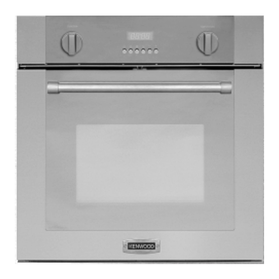
1 - CONTROL PANEL Fig. 1.1 CONTROL PANEL 1. Oven temperature knob 2. Function selector knob 3. Power on indicator light 4. Oven temperature indicator light 5. Electronic programmer TEMPERATURE CONTROL The temperature range is 50°C - 250°C (MAX setting). Fig. -
Page 8: How To Use The Oven
2 - HOW TO USE THE OVEN GENERAL FEATURES OPERATING PRINCIPLES The multi-function oven can be pro- Heating and cooking in the MULTI- grammed for 7 different functions to sat- FUNCTION oven are obtained in the fol- isfy every cooking need. lowing ways: a. - Page 9 Fig. 2.1 Fig. 2.2 FUNCTION SELECTOR KNOB TEMPERATURE KNOB (fig. 2.2) (fig. 2.1) Rotate the knob clockwise to set the To turn on the heating elements of the oven to one of the following functions: oven, set the function selector knob to the required position and the tempera- ture knob to the desired temperature.
- Page 10 GRILLING The infra-red heating element is switched on. The heat is diffused by radiation. Use with the oven door closed and the temperature knob set between 50°C and 200°C max. For correct use see chapter “USE OF THE GRILL”. Recommended for: Intense grilling action for cooking with the broiler;...
- Page 11 VENTILATED GRILL COOKING The infra-red grill and the fan are on. The heat is mainly diffused by radiation and the fan then distributes it throughout the oven. The temperature must be regulated between 50°C and 200°C max with the temperature knob.
- Page 12 COOKING ADVICE GRILLING AND “AU GRATIN” Grilling may be done using the grill+fan setting , in this setting the hot air ROASTING completely surrounds the food that is to To obtain classical roasting, it is neces- be cooked, to give a more even and sary to remember: rapid cooking process.
-
Page 13: Electronic Programmer
3 - ELECTRONIC PROGRAMMER The electronic programmer performs the Description of the illuminated symbols: following functions: – 24 hours clock with illuminated display AUTO - flashing - Programmer in auto- matic position but not pro- – Timer (up to 23 hours and 59 minutes) grammed –... - Page 14 ELECTRONIC CLOCK ELECTRONIC TIMER (fig. 3.2) The programmer is equipped with an The timer consists only of a buzzer electronic clock with an illuminated dis- which may be set for a maximum period play which indicates hours and minutes. of 23 hours and 59 minutes. Upon immediate connection of the oven If the AUTO symbol is flashing push the or after a power cut, three zeros will...
- Page 15 AUTOMATIC OVEN COOKING 3. Set the temperature and the cooking program by using the function selector To cook food automatically in the oven, switch and temperature knobs of the it is necessary to: oven (see specific chapters). 1. Set the length of the cooking time 2.
- Page 16 SEMI - AUTOMATIC COOKING At the end of the cooking period, the symbol will disappear, AUTO will flash This is used to automatically switch off and a buzzer will sound and can be the oven after the desired cooking peri- stopped by pushing any of the buttons od has elapsed.
-
Page 17: Cleaning & Maintenance
4 - CLEANING AND MAINTENANCE GENERAL ADVICE STAINLESS STEEL AND ALUMINIUM PARTS AND SILK-SCREEN PRINTED Important: SURFACES Before cleaning or carrying out any maintenance disconnect the appli- Clean using an appropriate product. ance from the electrical supply. Always dry thoroughly. It is advisable to clean when the appli- ance is cold especially when cleaning IMPORTANT: these parts must be... - Page 18 WIRE RACKS REPLACING THE OVEN LIGHT – Assemble the wire racks to the oven Before any maintenance is started walls using the 2 screws (Fig. 4.1). involving electrical parts of the appliance, – Slide into the guides, the shelf and the it must be disconnected from the power tray (fig.
- Page 19 REMOVING THE OVEN DOOR The oven door can easily be removed as follows: – Open the door to the full extent (fig. 4.4a). – Open the lever “A” completely on the left and right hinges (fig. 4.4b). – Hold the door as shown in fig. 4.4. Fig.
-
Page 20: Advice For The Installer
Advice for the installer IMPORTANT Appliance installation and maintenance must only be carried out by QUALIFIED TECH- NICIANS and in compliance with the local safety standards. Failure to observe this rule will invalidate the warranty. Always unplug the appliance before carrying out any maintenance operations or repairs. -
Page 21: Installation
5 - INSTALLATION IMPORTANT – The appliance should be installed by a QUALIFIED INSTALLATION TECHNICIAN. The appliance must be installed in compliance with regulations in force. The oven can be fitted in standard units, width and depth 60 cm. Installation requires a compartment as illustrated in figures 5.1 and 5.2. - Page 22 50 mm 30 mm Fig. 5.3 Fig. 5.4 To ensure internal ventilation, aeration channels must be provided as illustrated in the fig- ures 5.3 and 5.4.
- Page 23 OVEN DOOR LOWER TRIM AIR FLOW Fig. 5.5 IMPORTANT: To avoid damage to the lower trim please note the following instructions. The lower trim is designed to allow for good air circulation and the correct opening of the oven door. To ensure the trim is not damaged due to the appliance being placed on the floor, the appliance should be suitably supported as in above illustrations.
-
Page 24: Electrical Installation
6 - ELECTRICAL SECTION ELECTRICAL CONNECTION For your safety please read the following information Warning: This appliance must be earthed. – The appliance must be connected to a GREEN AND YELLOW 220-240 volts 50 cycle AC supply by Earth means of a three pin socket, suitably BLUE BROWN Neutral... - Page 25 Important The wires in the mains lead on this appliance are coloured in accordance with the follow- ing code: Green and Yellow - Earth Blue – Neutral Brown – Live – As the colours may not correspond with the markings identifying the terminals in your plug proceed as follows.
-
Page 26: Guarantee & After Sales Service
GUARANTEE UK only If your appliance goes wrong within one year from the date you bought it, we will repair it (or replace it if necessary) free of charge provided: • you have not misused, neglected, or damaged it; • it has not been modified; •... - Page 27 Descriptions and illustrations in this booklet are given as simply indicative. The manufacturer reserves the right, considering the characteristics of the models described here, at any time and without notice, to make eventual necessary modifications for their construction or for commercial needs.
- Page 28 code 1102419 ß5 Part Number 56324/1...