U-Line 1215R User Manual
1000 series 15" solid door refrigerator
Hide thumbs
Also See for 1215R:
- User manual & service manual (70 pages) ,
- User manual (54 pages) ,
- User manual & service manual (60 pages)

Related Manuals for U-Line 1215R


Summary of Contents for U-Line 1215R
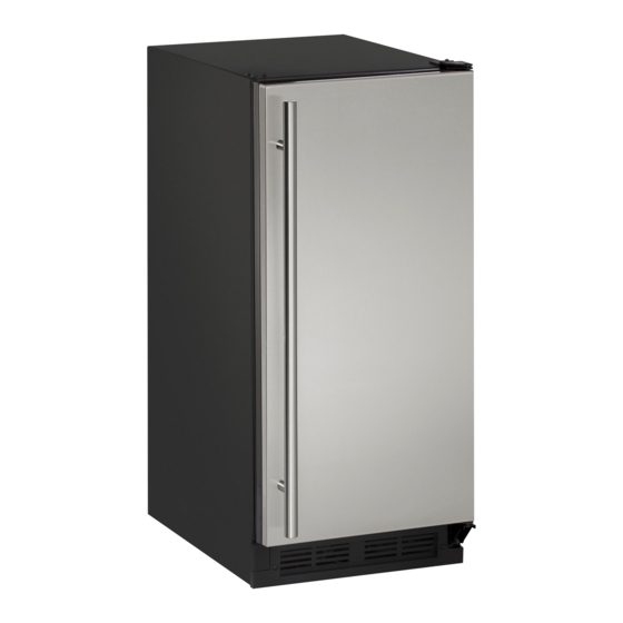
- Page 1 USER GUIDE SAFETY • INSTALLATION & INTEGRATION • OPERATING INSTRUCTIONS • MAINTENANCE • SERVICE RIGHT PRODUCT. RIGHT PLACE. RIGHT TEMPERATURE. SINCE 1962. 1000 Series 1215R 15" Solid Door Refrigerator • •...
-
Page 2: Table Of Contents
USER GUIDE u-line.com SAFETY • INSTALLATION & INTEGRATION • OPERATING INSTRUCTIONS • MAINTENANCE • SERVICE Contents Intro Extended Non-Use Safety Service Safety and Warning Accessories Disposal Troubleshooting Warranty Installation Environmental Requirements Electrical Cutout Dimensions Product Dimensions Side by Side Installation... - Page 3 1. U-Line Customer Care must be contacted immediately at +1.800.779.2547. 2. Service or repairs performed on the unit without prior written approval from U-Line is not permitted. If the unit has been altered or repaired in the field without prior written approval from U-Line, claims will not be eligible.
-
Page 4: Safety And Warning
USER GUIDE u-line.com SAFETY • INSTALLATION & INTEGRATION • OPERATING INSTRUCTIONS • MAINTENANCE • SERVICE Safety and Warning DANGER NOTICE This unit contains R600a (Isobutane) which is a Please read all instructions before installing, flammable hydrocarbon. It is safe for regular operating, or servicing the appliance. - Page 5 USER GUIDE u-line.com SAFETY • INSTALLATION & INTEGRATION • OPERATING INSTRUCTIONS • MAINTENANCE • SERVICE Disposal and Recycling DANGER RISK OF CHILD ENTRAPMENT. Before you throw away your old refrigerator or freezer, take off the doors and leave shelves in place so children may not easily climb inside.
-
Page 6: Environmental Requirements
USER GUIDE u-line.com SAFETY • INSTALLATION & INTEGRATION • OPERATING INSTRUCTIONS • MAINTENANCE • SERVICE Environmental Requirements This unit is designed to operate between 50°F (10°C) and 100°F (37°C). High ambient temperatures (100°F [37°C] or higher) may reduce the unit’s ability to reach low temperatures. - Page 7 USER GUIDE u-line.com SAFETY • INSTALLATION & INTEGRATION • OPERATING INSTRUCTIONS • MAINTENANCE • SERVICE Electrical WARNING SHOCK HAZARD — Electrical Grounding Required. Never attempt to repair or perform maintenance on the unit until the electricity has been disconnected. Never remove the round grounding prong from the plug and never use a two-prong grounding adapter.
-
Page 8: Cutout Dimensions
SAFETY • INSTALLATION & INTEGRATION • OPERATING INSTRUCTIONS • MAINTENANCE • SERVICE Cutout Dimensions PREPARE SITE Your U-Line product has been designed for either free- standing or built-in installation. When built-in, your unit does not require additional air space for top, sides, or rear. -
Page 9: Product Dimensions
USER GUIDE u-line.com SAFETY • INSTALLATION & INTEGRATION • OPERATING INSTRUCTIONS • MAINTENANCE • SERVICE Product Dimensions 23-1/4" (591 mm) (Includes 3/4" [20 mm] Integrated Panel) 34-1/8" to 35-1/8" (867 mm to 892 mm) 3-9/16" (91 mm) 14-15/16" (379 mm) -
Page 10: Side By Side Installation
USER GUIDE u-line.com SAFETY • INSTALLATION & INTEGRATION • OPERATING INSTRUCTIONS • MAINTENANCE • SERVICE Side-by-Side Installation 3. Place bracket over holes and attach to unit with two screws removed in step 2 using a T-25 Torx driver. Two units may be installed side-by-side. -
Page 11: Anti-Tip Bracket
USER GUIDE u-line.com SAFETY • INSTALLATION & INTEGRATION • OPERATING INSTRUCTIONS • MAINTENANCE • SERVICE Anti-Tip Bracket 1. Slide unit out so screws on top of unit are easily accessible. 2. Remove the two screws from the opposite side of the hinge assembly using a T-25 Torx driver (see below). -
Page 12: General Installation
USER GUIDE u-line.com SAFETY • INSTALLATION & INTEGRATION • OPERATING INSTRUCTIONS • MAINTENANCE • SERVICE General Installation INSTALLATION 1. Plug in the power/electrical cord. LEVELING INFORMATION 1. Use a level to confirm 2. Gently push the unit into position. Be careful not to the unit is level. -
Page 13: Integrated Panel Dimensions
USER GUIDE u-line.com SAFETY • INSTALLATION & INTEGRATION • OPERATING INSTRUCTIONS • MAINTENANCE • SERVICE Integrated Panel Dimensions Integrated Panel Dimensions INTEGRATED PANEL BACK SURFACE MUST HAVE AMPLE FLAT SURFACE TO MOUNT OVERLAY PANEL FLAT AND WITHOUT 3/4" INTERFERENCE (20 mm) NOTICE 14-3/4"... -
Page 14: Integrated Panel Installation
Integrated Panel Installation 6. Secure integrated panel to door/drawer Clamp 1. Fully open door/drawer. using clamps. A robust tape may also be used. U-Line 2. Starting at corner, pull recommends the use gasket away from door/ of bar clamps to drawer. Door/Drawer secure the panel to the door/drawer. - Page 15 USER GUIDE u-line.com SAFETY • INSTALLATION & INTEGRATION • OPERATING INSTRUCTIONS • MAINTENANCE • SERVICE 11.Remove clamps from door/drawer. NOTICE If panel requires additional adjustment after removing clamps, slightly loosen each screw and adjust panel as necessary. Tighten screws upon completion.
-
Page 16: Grille / Plinth Installation
USER GUIDE u-line.com SAFETY • INSTALLATION & INTEGRATION • OPERATING INSTRUCTIONS • MAINTENANCE • SERVICE Grille - Plinth Installation REMOVING AND INSTALLING GRILLE WARNING Disconnect electric power to the unit before removing the grille. WARNING DO NOT touch the condenser fins (4). The condenser fins are SHARP and can be easily damaged. -
Page 17: Door Swing
USER GUIDE u-line.com SAFETY • INSTALLATION & INTEGRATION • OPERATING INSTRUCTIONS • MAINTENANCE • SERVICE Door Swing Wall Wall 1/4" Min. 2-1/8" Min. (6 mm) (54 mm) Door Swing Door Swing Units have a zero clearance for the door to open 90°, when installed adjacent to cabinets. -
Page 18: Door Stop
3. On 24" models, a second pin is included for the bottom hinge. Repeat steps above for second hinge. Your U-Line unit was shipped to you with the optional 90° pin(s). (Models that are 15" wide include 1 pin. Models NOTE: Threaded pin will be inserted from the bottom. -
Page 19: Door Adjustments
USER GUIDE u-line.com SAFETY • INSTALLATION & INTEGRATION • OPERATING INSTRUCTIONS • MAINTENANCE • SERVICE Door Adjustments DOOR ALIGNMENT AND ADJUSTMENT Align and adjust the door if it is not level or is not sealing properly. If the door is not sealed, the unit may not cool properly, or excessive frost may form in the interior. - Page 20 USER GUIDE u-line.com SAFETY • INSTALLATION & INTEGRATION • OPERATING INSTRUCTIONS • MAINTENANCE • SERVICE 3. Remove door by tilting forward and lifting door off Install top hinge and door: bottom hinge. Retain shoulder washer; it will be 1. Reinstall the screws.
-
Page 21: First Use
USER GUIDE u-line.com SAFETY • INSTALLATION & INTEGRATION • OPERATING INSTRUCTIONS • MAINTENANCE • SERVICE First Use All U-Line controls are preset at the factory. Initial startup requires no adjustments. NOTICE U-Line recommends allowing the unit to run overnight before loading with product. -
Page 22: Control Operation
USER GUIDE u-line.com SAFETY • INSTALLATION & INTEGRATION • OPERATING INSTRUCTIONS • MAINTENANCE • SERVICE Control Operation Alert Up Down Light Power Used CONTROL FUNCTION GUIDE FUNCTION COMMAND DISPLAY/OPTIONS ON/OFF Press and release Unit will immediately turn ON or OFF. -
Page 23: Sabbath Mode
The unit will still maintain internal temperatures and set points. View a full list of Star-K certified U-Line units at www.star-k.org. To enable Sabbath Mode. 1. Press (4) and hold for ten seconds and release (the °F/°C symbol will flash briefly at the end of the ten... -
Page 24: Airflow And Product Loading
Anything in direct contact with the evaporator is subject to freezing. When properly loaded, your U-Line unit will store up to 92 (12 oz. [330 ml]) cans or 57 (12 oz. [330 ml]) bottles. Airflow and Product Loading 1... -
Page 25: Interior Shelves
USER GUIDE u-line.com SAFETY • INSTALLATION & INTEGRATION • OPERATING INSTRUCTIONS • MAINTENANCE • SERVICE Interior Shelves NOTICE Make sure the shelves are inserted fully into the REMOVING AND INSTALLING INTERIOR unit. SHELVES The edge strip toward the rear prevents cans and bottles from freezing against the cold evaporator. -
Page 26: Maintenance
For best results use Claire Stainless Steel Disconnect power to the unit. Polish and Cleaner, which can be purchased from U-Line Corporation (Part Number 173348). Comparable products are acceptable. Frequent cleaning will remove surface Clean the interior and all removed components using a contamination that could lead to rust. - Page 27 USER GUIDE u-line.com SAFETY • INSTALLATION & INTEGRATION • OPERATING INSTRUCTIONS • • SERVICE MAINTENANCE High ambient temperature and excessive humidity can also produce frost. CAUTION DO NOT use an ice pick or other sharp instrument to help speed up defrosting. These instruments can puncture the inner lining or damage the cooling unit.
-
Page 28: Cleaning Condenser
USER GUIDE u-line.com SAFETY • INSTALLATION & INTEGRATION • OPERATING INSTRUCTIONS • MAINTENANCE • SERVICE Cleaning Condenser INTERVAL - EVERY SIX MONTHS To maintain operational efficiency, keep the front grille free of dust and lint, and clean the condenser when necessary. -
Page 29: Extended Non-Use
USER GUIDE u-line.com SAFETY • INSTALLATION & INTEGRATION • OPERATING INSTRUCTIONS • MAINTENANCE • SERVICE Extended Non-Use 5. During periods of non-use, the cabinet must remain open to prevent formation of mold and mildew. Open STORAGE, VACATION AND MOVING door a minimum of 2 in. (5 cm) to provide the necessary ventilation. -
Page 30: Accessories
USER GUIDE u-line.com SAFETY • INSTALLATION & INTEGRATION • OPERATING INSTRUCTIONS • MAINTENANCE • SERVICE Accessories 80-51004-00 23054-01 Accessories - Anti-Tip Accessories - Stainless Steel Mounting Brackets PRO Style Door Handle, US$18.99 1-1/4" in diameter US$49.00 Accessories 1... -
Page 31: Troubleshooting
• Evaporator: Refrigerant flowing through an evaporator may sound like boiling liquid. BEFORE CALLING FOR SERVICE If you think your U-Line product is malfunctioning, read • Condenser Fan: Air moving through a condenser may the CONTROL OPERATION section to clearly understand be heard. - Page 32 USER GUIDE u-line.com SAFETY • INSTALLATION & INTEGRATION • OPERATING INSTRUCTIONS • MAINTENANCE • SERVICE 6. After 24 hours, check the temperature of the water. If Problem Possible Cause and Remedy required, adjust the temperature control in a small Product Is Because product in contact with the rear wall increment (see CONTROL OPERATION).
-
Page 33: Warranty
God, such as fire, floods, wind and U-Line product to be free from defects in materials and lightning; damages incurred or resulting from shipping, workmanship for a period of five years from the date of improper installation, unauthorized modification, or purchase. - Page 34 7. If a product defect is discovered during the applicable warranty period, you must promptly notify either U-Line at 8900 N. 55th Street, Milwaukee, Wisconsin 53223 USA or at +1.800.779.2547 or the dealer from whom you purchased the product. In no event shall such notification be received later than 30 days after the expiration of the applicable warranty period.