Walkera QR X350 Quick Start Manual And Systems Flowchart
Hide thumbs
Also See for QR X350:
- User handbook manual (19 pages) ,
- User manual (2 pages) ,
- User handbook manual (19 pages)
Advertisement
Quick Links
Download this manual
See also:
User Manual
1.1 Prepare quadcopter landing
gear and 4 screws.
1.3 Secure the landing gear with
2 screws, tighten firmly with
your fingers, do not use tools.
1.2 Install the right skid, carefully
pull the cables and the antenna
throu the holes in the landing gear.
2.4 DONE, the prop arrows
should now match this
illustration, please check.
2.1 Prepare 4 propellers and
the rounded "nuts" , these
are called "Spinners".
2.3 Screw the "spinner" on
Then tighten using one of the
allen wrenches in the kit.
2.2 Match the concave part on the propeller to the concave
part on the brushless motor. Match the arrow on the arm
to the arrow on the propellers. Double check, this is important.
4.3 Plug the camera cable into
the gimble controller.
4.5 Wiring is done, make sure
the camera cable is free so
the camera can move freely.
4.4 Connect the camera cable
to the power wire
from the QR X350PRO quad.
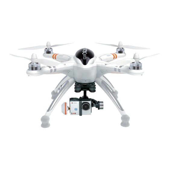
4.6 Congratulations,
you have successfully
assembled your QR X350PRO.
4.2 Secure the camera with the
mounting bracket, the bracket
have a rounded cut for the lens.
Quick Start Guide and Systems Flowchart
4.1 Prepare the iLook camera
`walkera
QR X350
R CI)
GPS altitude hold system
O
Install the Landing gear
1.4 Install the left skid, carefully
pull the cable throu the hole
in the landing gear.
1.5 Secure the landing gear with
2 screws, tighten firmly with
your fingers, do not use tools.
1.6 Connect compass.
1.7 Secure the cable by pushing it
under the "clip" on the compass
mounting part.
1.8 Secure the cable into the
hollow part of the leg with
one of the supplied foam
tape strips.
1.9 Congratulations, you have
installed the landing gear
next let's install the propellers.
O
Install the Propellers
•
•
Install the G-2D Brushless Gimble
NOTE: The G-2D gimble is a lightweight gimble, it is a delicate high-performance gimble, ALWAYS handle it by the base, stressing the arms may dammage the bearings and affect the performance of the gimble.
3.2 Slide the gimble onto the mounting
track, push on the base until it is all
the way back.
3.4 Insert the signal wires, match the text on
the wire to the text on the controller, the wire
go on the back pin away from the edge.
3.5 Gimble install is finished.
The wires should now
match the illustration.
O
Install the iLook digital camera
•
3.1 Prepare the G-2D gimble.
3.3 Done, the gimble is installed.
Advertisement


