Table of Contents
Advertisement
Quick Links
Advertisement
Table of Contents

Related Manuals for Honeywell 5010


Summary of Contents for Honeywell 5010
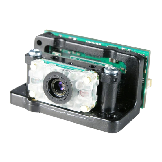
- Page 1 5X10/5X80 5010/80, 5110/80, 5310/80 User’s Guide...
- Page 2 Disclaimer Honeywell International Inc. (“HII”) reserves the right to make changes in speci- fications and other information contained in this document without prior notice, and the reader should in all cases consult HII to determine whether any such changes have been made. The information in this publication does not repre- sent a commitment on the part of HII.
- Page 3 Nijverheidsweg 9-13 5627 BT Eindhoven The Netherlands Honeywell shall not be liable for use of our product with equipment (i.e., power supplies, personal computers, etc.) that is not CE marked and does not comply with the Low Voltage Directive. CB Scheme...
- Page 4 ESD Precautions The 5X10/80 is shipped in ESD safe packaging. Use care when handling the scan engine outside its packaging. Be sure grounding wrist straps and properly grounded work areas are used. Dust and Dirt The 5X10/80 must be sufficiently enclosed to prevent dust particles from gathering on the imager and lens.
-
Page 5: Table Of Contents
Table of Contents Chapter 1 - Getting Started Introduction ..............1-1 About This Manual ............1-1 Unpacking the Engine ..........1-1 OEM Engine Models ........... 1-2 Connecting the Development Engine to the PC..1-3 Chapter 2 - Getting Connected Plug and Play .............. 2-1 RS-232 .............. - Page 6 Good Read Indicators..........4-1 Beeper – Good Read ..........4-1 Beeper Volume – Good Read........ 4-2 Beeper Pitch – Good Read ........4-2 Beeper Duration – Good Read ......4-3 LED – Good Read ..........4-3 LED Good Read Polarity ........4-3 Number of Beeps –...
- Page 7 No Read ..............4-23 Print Weight............... 4-24 Video Reverse............4-24 Working Orientation ..........4-25 Chapter 5 - Data Editing Prefix/Suffix Overview ..........5-1 To Add a Prefix or Suffix: ..........5-2 To Clear One or All Prefixes or Suffixes:....5-3 To Add a Carriage Return Suffix to All Symbologies............
- Page 8 Chapter 7 - Symbologies Message Length Description ........7-2 Codabar Start/Stop Characters ......7-3 Codabar Check Character ........7-3 Codabar Concatenation ......... 7-4 Codabar Message Length ........7-5 Code 39 Start/Stop Characters ......7-6 Code 39 Check Character ........7-6 Code 39 Message Length........
- Page 9 UPC-A/EAN-13 with Extended Coupon Code... 7-24 UPC-E0 Expand ..........7-25 UPC-E0 Addenda Required ........ 7-26 UPC-E0 Addenda Separator ....... 7-26 UPC-E0 Check Digit..........7-26 UPC-E0 Number System ........7-27 UPC-E0 Addenda..........7-27 EAN/JAN-13 Check Digit........7-29 EAN/JAN-13 Addenda......... 7-29 EAN/JAN-13 Addenda Required ......7-30 EAN/JAN-13 Addenda Separator......
- Page 10 EAN•UCC Composite Codes........7-44 UPC/EAN Version..........7-45 EAN•UCC Composite Code Message Length ..7-45 Postnet..............7-47 Planet Code ............7-48 British Post............7-48 Canadian Post ............. 7-48 Kix (Netherlands) Post ......... 7-49 Australian Post............. 7-49 Japanese Post ............. 7-49 China Post Message Length........ 7-50 Korea Post Message Length .......
- Page 11 OCR Check Character ..........9-8 OCR Modulo 10 Check Character......9-9 OCR Modulo 36 Check Character......9-9 OCR User-Defined Check Character ......9-9 Weighting Options ..........9-10 OCR ISBN Application Example ....... 9-12 OCR Template Codes ..........9-14 Chapter 10 - Utilities To Add a Test Code I.D.
- Page 12 Troubleshooting ............12-2 Chapter 13 - Customer Support Product Service and Repair........13-1 Technical Assistance ..........13-1 Limited Warranty............13-1 Appendix A - Reference Charts Symbology Chart ............A-1 ASCII Conversion Chart (Code Page 1252) ....A-3 Code Page Mapping of Printed Bar Codes....A-5...
-
Page 13: Chapter 1 - Getting Started
Product specifications, dimensions, warranty, and customer support information are also included. Honeywell’s bar code engines are factory programmed for the most common terminal and communications settings. If you need to change these settings, programming is accomplished by scanning the bar codes in this guide. -
Page 14: Oem Engine Models
OEM Engine Models There are three models of the OEM Engine, which may be used with many interfaces described in this manual. Refer to the chart below to determine the models that can be used with your interface. The following interfaces apply to all OEM Engine focal distances and decoding options. -
Page 15: Connecting The Development Engine To The Pc
2. If using a USB connection, connect the included interface cable to the engine and to the matching USB port on the back of the computer. Skip to step 5. Note: For additional USB programming and technical information, refer to Honeywell’s “USB Application Note,” available at www.honeywellaidc.com 1 - 3... - Page 16 3. If using an RS-232 connection, connect the serial interface cable to the engine and to the matching port on the back of the computer. 4. Connect the power supply connector to the serial interface cable. Plug in the power supply. 5.
-
Page 17: Reading Techniques
Reading Techniques The engine has a view finder that projects a bright red or green aiming beam that corresponds to the engine’s horizontal field of view. The aiming beam should be centered over the bar code, but it can be positioned in any direction for a good read. - Page 18 symbols (on a page or on an object), hold the engine at an appropriate distance from the target, send a trigger command, and center the aiming beam on the symbol. If the code being scanned is highly reflective (e.g., laminated), it may be necessary to tilt the code +5°...
-
Page 19: Chapter 2 - Getting Connected
Getting Connected Plug and Play Plug and Play bar codes provide instant engine set up for commonly used interfaces. Note: After you scan one of the codes, power cycle the host terminal to have the interface in effect. RS-232 The RS-232 Interface bar code is used when connecting to the serial port of a PC or terminal. -
Page 20: Usb Hid
® 232-based COM port. If you are using a Microsoft Windows PC, you will need to download a driver from the Honeywell website www.honeywellaidc.com . The driver will use the next available COM port number. Apple® Macintosh computers recognize the engine as a USB CDC class device and automatically use a class driver. - Page 21 RS-232 True and RS-232 TTL RS-232 True and RS-232 TTL USB PC Keyboard USB PC Keyboard USB Mac Keyboard USB Mac Keyboard IBM SurePOS (Handheld Imager) USB SurePOS (Handheld Imager) USB IBM SurePOS (Tabletop Imager) USB IBM SurePOS (Tabletop Imager) 2 - 3...
- Page 22 USB HID POS USB HID POS USB Japanese Keyboard USB Japanese Keyboard (PC) CTS/RTS Emulation * Off ACK/NAK Mode * Off 2 - 4...
-
Page 23: Chapter 3 - Terminal Interfaces
Terminal Interfaces Terminal ID If you want to change the pre-programmed interface of your image engine, refer Supported Terminals, below. For example, a USB HID POS device has a Terminal ID of 131. You would scan the Terminal ID bar code, then 1, 3, 1 from the Programming Chart inside the back cover of this manual, then Save. -
Page 24: Rs-232 Baud Rate
RS-232 Baud Rate Baud Rate sends the data from the imager to the terminal at the specified rate. The host terminal must be set for the same baud rate as the imager. Default = 115,200 . 1200 2400 4800 9600 19200 38400 57,600... -
Page 25: Rs-232 Word Length: Data Bits, Stop Bits, And Parity
RS-232 Word Length: Data Bits, Stop Bits, and Parity Data Bits sets the word length at 7 or 8 bits of data per character. If an application requires only ASCII Hex characters 0 through 7F decimal (text, digits, and punctuation), select 7 data bits. For applications which require use of the full ASCII set, select 8 data bits per character. -
Page 26: Rs-232 Receiver Time-Out
RS-232 Receiver Time-Out The unit stays awake to receive data until the RS-232 Receiver Time-Out expires. A trigger command resets the time-out. When an RS-232 receiver is sleeping, a character may be sent to wake up the receiver and reset the time- out. -
Page 27: Ttl Level 232 Interface
RTS/CTS On * RTS/CTS Off XON/XOFF On * XON/OFF Off ACK/NAK On * ACK/NAK Off TTL Level 232 Interface The 5X80 provides a TTL level serial 232 communication link. TTL Level 232 Inverted is the “normal” mode that allows direct communication from the 5X80 to a standard PC RS-232 serial port with the use of cable (part number 42206139- 04). - Page 28 Default = TTL Level 232 Inverted with Polarity Override. TTL Level 232 Inverted TTL Level 232 Non-Inverted * TTL Level 232 Inverted with Polarity Override 3 - 6...
-
Page 29: Chapter 4 - Output
Output Image VGA You can set the image size to a VGA resolution, if necessary, to accommodate older applications that require a smaller image size. When Image VGA is set to On, the resultant image is 640x480 pixels. When Image VGA is Off, your image is 752x480 pixels. -
Page 30: Beeper Volume - Good Read
Beeper Volume – Good Read The beeper volume codes modify the volume of the beep the imager emits on a good read. Default = Medium for the 5X10, High for the 5X80. Medium High Beeper Pitch – Good Read The beeper pitch codes modify the pitch (frequency) of the beep the imager emits on a good read. -
Page 31: Beeper Duration - Good Read
Beeper Duration – Good Read The beeper duration codes modify the length of the beep the imager emits on a good read. Default = Normal. * Normal Beep Short Beep LED – Good Read The LED indicator can be programmed On or Off in response to a good read. Default = On. -
Page 32: Number Of Beeps - Good Read
If the LED is enabled for a good read (see LED – Good Read on page 4-3), the polarity change takes effect after the next successful decode or a power cycle. If the LED is disabled, a polarity change only takes effect after a power cycle. Default = Active Low. -
Page 33: Beep Polarity
Beep Polarity Beep Polarity sets the idle and active states of the beeper signal. When set to Active High , the beeper sounds when the signal shifts from low to high. When set to Active Low , the beeper sounds when the signal shifts from high to low. If the beeper is enabled for a good read (see Beeper –... -
Page 34: User-Specified Good Read Delay
User-Specified Good Read Delay If you want to set your own length for the good read delay, scan the bar code below, then set the delay (from 0-30,000 milliseconds) by scanning digits from the inside back cover, then scanning Save . User-Specified Good Read Delay Trigger Modes Manual/Serial Trigger... -
Page 35: Snap And Ship
Manual Trigger, Low Power Note: For RS-232 and HHLC mode only. The imager powers down until the trigger is pulled. When the trigger is pulled, the imager powers up and operates until there is no triggering for the time set with the Low Power Time-Out bar code below. -
Page 36: Host Notify Mode
Host Notify Mode Note: For RS-232 and USB communications only. Host Notify Mode bypasses the decoder and notifies the host that there has been a hardware trigger pull. When in Host Notify Mode, it is up to the host to initiate an Image Snap and/or an Image Ship command (see Imaging Commands... -
Page 37: Presentation Mode
Presentation Mode This programs the imager to work in Presentation mode. The LEDs are either off or at the lowest power for ambient conditions until a bar code is presented to the imager. Then the LEDs turn on automatically to read the code. Presentation Mode uses ambient light to detect the bar codes. -
Page 38: Presentation Sensitivity
Presentation Sensitivity Presentation Sensitivity is a numeric range that increases or decreases the imager's reaction time to bar code presentation. To set the sensitivity, scan the Sensitivity bar code, then scan the degree of sensitivity (from 0-20) from the inside back cover, and Save . 0 is the most sensitive setting, and 20 is the least sensitive. -
Page 39: Reread Delay
Reread Delay This sets the time period before the imager can read the same bar code a second time. Setting a reread delay protects against accidental rereads of the same bar code. Longer delays are effective in minimizing accidental rereads at POS (point of sale). -
Page 40: Led Power Level
LED Power Level This selection allows you to adjust LED and aimer brightness. Off is used when no illumination is needed. Low is used if low illumination is sufficient. High (the default) is the brightest setting. If you have an aimer delay programmed (see Aimer Delay on page 4-13), the aimer will be at 100% power during the delay, regardless of the LED Power... -
Page 41: Imager Time-Out
Imager Time-Out Imager Time-Out powers down the imager after the unit has been idle for the specified time. To prevent the imager from powering down, set this time-out to 0. Scan the bar code below, then set the time-out by scanning digits (from 0 - 999,999 ms) from the inside back cover, then scanning Save . -
Page 42: Aimer Modes
Aimer Modes Interlaced In interlaced mode, the illumination and aiming timing is automatically synchronized to the imager exposure period by the Image Engine. The engine turns illumination on while the image is being exposed, and it turns the aiming off at all other times. The interlaced mode provides the lowest overall current draw and is recommended for most applications. -
Page 43: Thermal Considerations
Thermal Considerations Care must be taken when designing the Image Engine into any system. Internal heating of the Image Engine can occur in high duty cycle scanning applications in several ways. The high visibility aimer dissipates a significant amount of power as heat. - Page 44 In the example below, the gray box indicates the centering window. The centering window has been set to 20% left, 30% right, 25% top, and 42% bottom. Since Bar Code 1 passes through the centering window, it will be read. Bar Code 2 does not pass through the centering window, so it will not be read.
-
Page 45: Decode Search Mode
Scan Centering On , then scan one of the following bar codes to change the top, bottom, left, or right of the centering window. Then scan the percent you want to shift the centering window using digits on the inside back cover of this manual. Scan Save . - Page 46 Quick Omnidirectional - This is an abbreviated search for bar code features around the center region of an image. This mode quickly reads all symbologies in any orientation. The Quick Omnidirectional mode may miss some off-center symbols, as well as larger Data Matrix and QR Code symbols. Quick Omnidirectional Advanced Linear Decoding - Performs quick horizontal linear scans in a center band of the image.
-
Page 47: Output Sequence Overview
Output Sequence Overview Require Output Sequence When turned off, the bar code data will be output to the host as the Imager decodes it. When turned on, all output data must conform to an edited sequence or the Imager will not transmit the output data to the host device. Note: This selection is unavailable when the Multiple Symbols Selection is turned on. - Page 48 Other Programming Selections • Discard This exits without saving any Output Sequence changes. Output Sequence Example In this example, you are scanning Code 93, Code 128, and Code 39 bar codes, but you want the imager to output Code 39 1st, Code 128 2nd, and Code 93 3rd, as shown below.
-
Page 49: Output Sequence Editor
9999 code length that must match for Code 93, 9999 = all lengths start character match for Code 93, 43h = “C” termination string for third code To program the previous example using specific lengths, you would have to count any programmed prefixes, suffixes, or formatted characters as part of the length. -
Page 50: Multiple Symbols
When the output sequence is Off , the bar code data is output to the host as the imager decodes it. Note: This selection is unavailable when the Multiple Symbols Selection is turned on. Required On/Not Required *Off Multiple Symbols Note: This feature does not work when the Imager is in Low Power mode. -
Page 51: No Read
No Read With No Read turned On , the Imager notifies you if a code cannot be read. If using a Quick*View Scan Data Window, an “NR” appears when a code cannot be read. If No Read is turned Off , the “NR” will not appear. * Off If you want a different notation than “NR,”... -
Page 52: Print Weight
Print Weight Print Weight is used to adjust the way the imager reads Matrix symbols. If a imager will be seeing consistently heavily printed matrix symbols, then a print weight of 6 may improve the reading performance. For consistently light printing, a print weight of 2 may help. -
Page 53: Working Orientation
Working Orientation Some bar codes are direction-sensitive. For example, Kix codes and OCR can misread when scanned sideways or upside down. Use the working orientation settings if your direction-sensitive codes will not usually be presented upright to the scanner. Default = Upright. Upright: Rotate Clockwise 90°: Upside Down:... - Page 54 4 - 26...
-
Page 55: Chapter 5 - Data Editing
Data Editing Prefix/Suffix Overview When a bar code is scanned, additional information is sent to the host computer along with the bar code data. This group of bar code data and additional, user-defined data is called a “message string.” The selections in this section are used to build the user-defined data into the message string. -
Page 56: To Add A Prefix Or Suffix
To Add a Prefix or Suffix: Step 1. Scan the Add Prefix or Add Suffix symbol (page 5-4). Step 2. Determine the 2 digit Hex value from the Symbology Chart (included in Appendix A) for the symbology to which you want to apply the prefix or suffix. -
Page 57: To Clear One Or All Prefixes Or Suffixes
To Clear One or All Prefixes or Suffixes: You can clear a single prefix or suffix, or clear all prefixes/suffixes for a symbology. When you Clear One Prefix (Suffix), the specific character you select is deleted from the symbology you want. When you Clear All Prefixes (Suffixes), all the prefixes or suffixes for a symbology are deleted. -
Page 58: Prefix Selections
Prefix Selections Add Prefix Clear One Prefix Clear All Prefixes Suffix Selections Add Suffix Clear One Suffix Clear All Suffixes Function Code Transmit When this selection is enabled and function codes are contained within the scanned data, the imager transmits the function code to the terminal. Default = Enable. -
Page 59: Intercharacter, Interfunction, And Intermessage Delays
Intercharacter, Interfunction, and Intermessage Delays Some terminals drop information (characters) if data comes through too quickly. Intercharacter, interfunction, and intermessage delays slow the transmission of data, increasing data integrity. Each delay is composed of a 5 millisecond step. You can program up to 99 steps (of 5 ms each) for a range of 0-495 ms. -
Page 60: User Specified Intercharacter Delay
User Specified Intercharacter Delay An intercharacter delay of up to 495 milliseconds may be placed after the transmission of a particular character of scanned data. Scan the Delay Length bar code below, then scan the number of milliseconds and the SAVE bar code using the Programming Chart inside the back cover of this manual. -
Page 61: Intermessage Delay
Intermessage Delay An intermessage delay of up to 495 milliseconds may be placed between each scan transmission. Scan the Intermessage Delay bar code below, then scan the number of milliseconds and the SAVE bar code using the Programming Chart inside the back cover of this manual. 1st Scan Transmission 2nd Scan Transmission Intermessage Delay... - Page 62 5 - 8...
-
Page 63: Chapter 6 - Data Formatting
Data Formatting Data Format Editor Introduction You may use the Data Format Editor to change the imager’s output. For example, you can use the Data Format Editor to insert characters at certain points in bar code data as it is scanned. The selections in the following pages are used only if you wish to alter the output. -
Page 64: Other Programming Selections
cover to program the imager for your terminal ID (you must enter 3 dig- its). For example, scan 0 0 0 for RS-232. Note: The wildcard for all terminal types is 099. Step 4. Code I.D. Appendix A, find the symbology to which you want to apply the data format. - Page 65 (00-99) for the number of characters and xx stands for the hex value for an ASCII code. See ASCII Conversion Chart (Code Page 1252), page A-3.) F3 Send up to but not including “ss” character (Search and Send) starting from current cursor position, leaving cursor pointing to “ss”...
-
Page 66: Data Format Editor
and xxyy .. zz is the list of characters to be suppressed. (xx stands for the hex value for an ASCII code, see ASCII Conversion Chart (Code Page 1252), page A-3.) FC Disables suppress filter and clear all suppressed characters. Syntax = FC. E4 Replaces up to 15 characters in the data string with user specified charac- ters. -
Page 67: Data Formatter
Data Formatter When Data Formatter is turned off, the bar code data is output to the host as read (including prefixes and suffixes). Choose one of the following options. Default = Data Formatter On, but Not Required. * Data Formatter On, but Not Required Data Formatter Off When Data Formatter is required, all input data must conform to an edited format... - Page 68 6 - 6...
- Page 69 Symbologies This programming section contains the following menu selections. Refer to Chapter 11 for settings and defaults. • All Symbologies • Japanese Post • Kix (Netherlands) • Australian Post Post • Aztec Code • Korea Post • British Post • Matrix 2 of 5 •...
-
Page 70: Message Length Description
All Symbologies If you want to decode all the symbologies allowable for your imager, scan the All Symbologies On code. If on the other hand, you want to decode only a particular symbology, scan All Symbologies Off followed by the On symbol for that particular symbology. -
Page 71: Codabar Start/Stop Characters
Codabar <Default All Codabar Settings> Codabar * On Codabar Start/Stop Characters Start/Stop characters identify the leading and trailing ends of the bar code. You may either transmit, or not transmit Start/Stop characters. Default = Don’t Transmit . Transmit * Don’t Transmit Codabar Check Character Codabar check characters are created using different “modulos.”... -
Page 72: Codabar Concatenation
When Check Character is set to Validate, but Don’t Transmit , the unit will only read Codabar bar codes printed with a check character, but will not transmit the check character with the scanned data. * No Check Character Validate Modulo 16, but Don’t Transmit Validate Modulo 16 and Transmit... -
Page 73: Codabar Message Length
Codabar Message Length Scan the bar codes below to change the message length. Refer to Message Length Description (page 7-2) for additional information. Minimum and Maximum lengths = 2-60. Minimum Default = 4, Maximum Default = 60. Minimum Message Length Maximum Message Length 7 - 5... -
Page 74: Code 39 Start/Stop Characters
Code 39 < Default All Code 39 Settings > Code 39 * On Code 39 Start/Stop Characters Start/Stop characters identify the leading and trailing ends of the bar code. You may either transmit, or not transmit Start/Stop characters. Default = Don’t Transmit. -
Page 75: Code 39 Message Length
When Check Character is set to Validate, but Don’t Transmit, the unit only reads Code 39 bar codes printed with a check character, but will not transmit the check character with the scanned data. When Check Character is set to Validate and Transmit, the imager only reads Code 39 bar codes printed with a check character, and will transmit this character at the end of the scanned data. -
Page 76: Code 39 Append
Code 39 Append This function allows the imager to append the data from several Code 39 bar codes together before transmitting them to the host computer. When this function is enabled, the imager stores those Code 39 bar codes that start with a space (excluding the start and stop symbols), and does not immediately transmit the data. -
Page 77: Full Ascii
Full ASCII If Full ASCII Code 39 decoding is enabled, certain character pairs within the bar code symbol will be interpreted as a single character. For example: $V will be decoded as the ASCII character SYN, and /C will be decoded as the ASCII character #. -
Page 78: Code 39 Code Page
Code 39 Code Page Code pages define the mapping of character codes to characters. If the data received does not display with the proper characters, it may be because the bar code being scanned was created using a code page that is different from the one the host program is expecting. -
Page 79: Interleaved 2 Of 5 Message Length
When Check Digit is set to Validate and Transmit, the imager only reads Interleaved 2 of 5 bar codes printed with a check digit, and will transmit this digit at the end of the scanned data. Default = No Check Digit. * No Check Digit Validate, but Don’t Transmit Validate and Transmit... -
Page 80: Code 93 Message Length
Code 93 < Default All Code 93 Settings > Code 93 * On Code 93 Message Length Scan the bar codes below to change the message length. Refer to Message Length Description (page 7-2) for additional information. Minimum and Maximum lengths = 0-80. Minimum Default = 0, Maximum Default = 80. Minimum Message Length Maximum Message Length 7 - 12... -
Page 81: Code 93 Code Page
Code 93 Code Page Code pages define the mapping of character codes to characters. If the data received does not display with the proper characters, it may be because the bar code being scanned was created using a code page that is different from the one the host program is expecting. -
Page 82: Straight 2 Of 5 Industrial Message Length
Straight 2 of 5 Industrial (three-bar start/stop) <Default All Straight 2 of 5 Industrial Settings> Straight 2 of 5 Industrial * Off Straight 2 of 5 Industrial Message Length Scan the bar codes below to change the message length. Refer to Message Length Description (page 7-2) for additional information. -
Page 83: Straight 2 Of 5 Iata Message Length
Straight 2 of 5 IATA (two-bar start/stop) <Default All Straight 2 of 5 IATA Settings> Straight 2 of 5 IATA * Off Straight 2 of 5 IATA Message Length Scan the bar codes below to change the message length. Refer to Message Length Description (page 7-2) for additional information. -
Page 84: Matrix 2 Of 5 Message Length
Matrix 2 of 5 <Default All Matrix 2 of 5 Settings> Matrix 2 of 5 * Off Matrix 2 of 5 Message Length Scan the bar codes below to change the message length. Refer to Message Length Description (page 7-2) for additional information. Minimum and Maximum lengths = 1-80. -
Page 85: Check Digits Required
Code 11 <Default All Code 11 Settings> Code 11 * Off Check Digits Required This option sets whether 1 or 2 check digits are required with Code 11 bar codes. Default = Two Check Digits. One Check Digit * Two Check Digits 7 - 17... -
Page 86: Code 11 Message Length
Code 11 Message Length Scan the bar codes below to change the message length. Refer to Message Length Description (page 7-2) for additional information. Minimum and Maximum lengths = 1-80. Minimum Default = 4, Maximum Default = 80. Minimum Message Length Maximum Message Length 7 - 18... -
Page 87: Isbt 128 Concatenation
Code 128 <Default All Code 128 Settings> Code 128 * On ISBT 128 Concatenation In 1994 the International Society of Blood Transfusion (ISBT) ratified a standard for communicating critical blood information in a uniform manner. The use of ISBT formats requires a paid license. The ISBT 128 Application Specification describes 1) the critical data elements for labeling blood products, 2) the current recommendation to use Code 128 due to its high degree of security and its space-efficient design, 3) a variation of Code 128 that supports concatenation of... -
Page 88: Code 128 Message Length
Code 128 Message Length Scan the bar codes below to change the message length. Refer to Message Length Description (page 7-2) for additional information. Minimum and Maximum lengths = 0-80. Minimum Default = 0, Maximum Default = 80. Minimum Message Length Maximum Message Length Code 128 Code Page Code pages define the mapping of character codes to characters. -
Page 89: Telepen Output
Telepen * Off Telepen Output Using AIM Telepen Output, the imager reads symbols with start/stop pattern 1 and decodes them as standard full ASCII (start/stop pattern 1). When Original Telepen Output is selected, the imager reads symbols with start/stop pattern 1 and decodes them as compressed numeric with optional full ASCII (start/stop pattern 2). -
Page 90: Upc-A Check Digit
UPC-A <Default All UPC-A Settings> UPC-A * On UPC-A Check Digit This selection allows you to specify whether the check digit should be transmitted at the end of the scanned data or not. Default = On . * On 7 - 22... -
Page 91: Upc-A Number System
UPC-A Number System The numeric system digit of a U.P.C. symbol is normally transmitted at the beginning of the scanned data, but the unit can be programmed so it will not transmit it. Default = On. * On UPC-A Addenda This selection adds 2 or 5 digits to the end of all scanned UPC-A data. -
Page 92: Upc-A Addenda Required
UPC-A Addenda Required When Required is scanned, the imager will only read UPC-A bar codes that have addenda. You must then turn on a 2 or 5 digit addenda listed on page 7- 23. Default = Not Required. Required * Not Required UPC-A Addenda Separator When this feature is on, there is a space between the data from the bar code and the data from the addenda. -
Page 93: Upc-E0 Expand
UPC-E0 <Default All UPC-E Settings> UPC-E0 Most U.P.C. bar codes lead with the 0 number system. For these codes, use the UPC-E0 selection. If you need to read codes that lead with the 1 number system, UPC-E1 (page 7-28). Default = On. * UPC-E0 On UPC-E0 Off UPC-E0 Expand... -
Page 94: Upc-E0 Addenda Required
UPC-E0 Addenda Required When Addenda Required is set to on, the imager will only read UPC-E bar codes that have addenda. Default = Not Required. Required * Not Required UPC-E0 Addenda Separator When this feature is on, there is a space between the data from the bar code and the data from the addenda. -
Page 95: Upc-E0 Number System
UPC-E0 Number System The numeric system digit of a U.P.C. symbol is normally transmitted at the beginning of the scanned data, but the unit can be programmed so it will not transmit it. Default = On. * On UPC-E0 Addenda This selection adds 2 or 5 digits to the end of all scanned UPC-E data. - Page 96 UPC-E1 Most U.P.C. bar codes lead with the 0 number system. For these codes, use UPC-E0 (page 7-25). If you need to read codes that lead with the 1 number system, use the UPC-E1 selection. Default = Off. UPC-E1 On * UPC-E1 Off EAN/JAN-13 <Default All EAN/JAN Settings>...
-
Page 97: Ean/Jan-13 Check Digit
EAN/JAN-13 * On EAN/JAN-13 Check Digit This selection allows you to specify whether the check digit should be transmitted at the end of the scanned data or not. Default = On. * On EAN/JAN-13 Addenda This selection adds 2 or 5 digits to the end of all scanned EAN/JAN-13 data. Default = Off for both 2 Digit and 5 Digit Addenda. -
Page 98: Ean/Jan-13 Addenda Required
EAN/JAN-13 Addenda Required When Addenda Required is set to on, the imager will only read EAN/JAN-13 bar codes that have addenda. Default = Not Required. Required * Not Required EAN/JAN-13 Addenda Separator When this feature is on, there is a space between the data from the bar code and the data from the addenda. -
Page 99: Ean/Jan-8 Check Digit
EAN/JAN-8 <Default All EAN/JAN-8 Settings> EAN/JAN-8 * On EAN/JAN-8 Check Digit This selection allows you to specify whether the check digit should be transmitted at the end of the scanned data or not. Default = On. * On 7 - 31... -
Page 100: Ean/Jan-8 Addenda
EAN/JAN-8 Addenda This selection adds 2 or 5 digits to the end of all scanned EAN/JAN-8 data. Default = Off for both 2 Digit and 5 Digit Addenda. 2 Digit Addenda On * 2 Digit Addenda Off 5 Digit Addenda On * 5 Digit Addenda Off EAN/JAN-8 Addenda Required When Addenda Required is set to on, the imager will only read EAN/JAN-8 bar... -
Page 101: Msi Check Character
<Default All MSI Settings> * Off MSI Check Character Different types of check characters are used with MSI bar codes. You can program the imager to read MSI bar codes with Type 10 check characters. Default = Validate Type 10, but Don’t Transmit. When Check Character is set to Validate and Transmit , the imager will only read MSI bar codes printed with the specified type check character, and will transmit this character at the end of the scanned data. -
Page 102: Msi Message Length
MSI Message Length Scan the bar codes below to change the message length. Refer to Message Length Description (page 7-2) for additional information. Minimum and Maximum lengths = 4-48. Minimum Default = 4, Maximum Default = 48. Minimum Message Length Maximum Message Length Plessey Code <Default All Plessey Code Settings>... -
Page 103: Plessey Message Length
Plessey Code * Off Plessey Message Length Scan the bar codes below to change the message length. Refer to Message Length Description (page 7-2) for additional information. Minimum and Maximum lengths = 4-48. Minimum Default = 4, Maximum Default = 48. Minimum Message Length Maximum Message Length RSS-14... -
Page 104: Rss Limited
RSS Limited < Default All RSS Limited Settings > RSS Limited * On RSS Expanded < Default All RSS Expanded Settings > 7 - 36... -
Page 105: Rss Expanded Message Length
RSS Expanded * On RSS Expanded Message Length Scan the bar codes below to change the message length. Refer to Message Length Description (page 7-2) for additional information. Minimum and Maximum lengths = 4-74. Minimum Default = 4, Maximum Default = 74. Minimum Message Length Maximum Message Length 7 - 37... -
Page 106: Posicode A And B
PosiCode <Default All PosiCode Settings> PosiCode A and B * On You have to have PosiCode A and B on to read any of the PosiCode symbologies. A and B On (No Limited) A and B and Limited A On (Limited B Off) * A and B and Limited B On (Limited A Off) -
Page 107: Posicode Message Length
PosiCode Message Length Scan the bar codes below to change the message length. Refer to Message Length Description (page 7-2) for additional information. Minimum and Maximum lengths = 2-80. Minimum Default = 4, Maximum Default = 48. Minimum Message Length Maximum Message Length Trioptic Code Note: If you are going to scan Code 32 Pharmaceutical codes... -
Page 108: Codablock F Message Length
Codablock F * Off Codablock F Message Length Scan the bar codes below to change the message length. Refer to Message Length Description (page 7-2) for additional information. Minimum and Maximum lengths = 1-2048. Minimum Default = 1, Maximum Default = 2048. Minimum Message Length Maximum Message Length Code 16K... -
Page 109: Code 16K Message Length
Code 16K * Off Code 16K Message Length Scan the bar codes below to change the message length. Refer to Message Length Description (page 7-2) for additional information. Minimum and Maximum lengths = 0-160. Minimum Default = 1, Maximum Default = 160. Minimum Message Length Maximum Message Length Code 49... -
Page 110: Code 49 Message Length
Code 49 * On Code 49 Message Length Scan the bar codes below to change the message length. Refer to Message Length Description (page 7-2) for additional information. Minimum and Maximum lengths = 1-81. Minimum Default = 1, Maximum Default = 81. Minimum Message Length Maximum Message Length 7 - 42... -
Page 111: Pdf417 Message Length
PDF417 < Default All PDF417 Settings > PDF417 * On PDF417 Message Length Scan the bar codes below to change the message length. Refer to Message Length Description (page 7-2) for additional information. Minimum and Maximum lengths = 1-2750. Minimum Default = 1, Maximum Default = 2750. Minimum Message Length Maximum Message Length MicroPDF417... -
Page 112: Micropdf417 Message Length
MicroPDF417 * Off MicroPDF417 Message Length Scan the bar codes below to change the message length. Refer to Message Length Description (page 7-2) for additional information. Minimum and Maximum lengths = 1-366. Minimum Default = 1, Maximum Default = 366. Minimum Message Length Maximum Message Length EAN•UCC Composite Codes... -
Page 113: Upc/Ean Version
UPC/EAN Version Scan the UPC/EAN Version On bar code to decode EAN•UCC Composite symbols that have a UPC or EAN linear component. (This does not affect EAN•UCC Composite symbols with a UCC/EAN-128 or RSS linear component.) UPC/EAN Version On * UPC/EAN Version Off EAN•UCC Composite Code Message Length Scan the bar codes below to change the message length. -
Page 114: Postal Codes
UCC Emulation • The imager can automatically format the output from any EAN•UCC data carrier to emulate what would be encoded in an equivalent UCC/EAN-128 or RSS and Composite symbol. EAN•UCC data carriers include UPC-A and UPC-E, EAN- 13 and EAN-8, ITF-14, UCC/EAN-128, and EAN•UCC RSS and Composites. Data from 2D symbols such as Aztec Code, Data Matrix, or QR Code, which encode a leading FNC1, also invoke EAN•UCC emulation. -
Page 115: Postnet
Postnet * Off Postnet Check Digit This selection allows you to specify whether the check digit should be transmitted at the end of the scanned data. Transmit Check Digit * Don’t Transmit Check Digit 7 - 47... -
Page 116: Planet Code
Planet Code * Off Planet Code Check Digit This selection allows you to specify whether the check digit should be transmitted at the end of the scanned data. Transmit Check Digit * Don’t Transmit Check Digit British Post * Off Canadian Post * Off 7 - 48... -
Page 117: Kix (Netherlands) Post
Kix (Netherlands) Post Note: Kix code can misread when scanned sideways or upside down. Use Working Orientation, page 4-25, if your Kix codes will not usually be presented upright to the scanner. * Off Australian Post * Off Japanese Post * Off China Post <Default All China Post Settings>... -
Page 118: China Post Message Length
China Post * Off China Post Message Length Scan the bar codes below to change the message length. Refer to Message Length Description (page 7-2) for additional information. Minimum and Maximum lengths = 2-80. Minimum Default = 4, Maximum Default = 80. Minimum Message Length Maximum Message Length 7 - 50... -
Page 119: Korea Post Message Length
Korea Post <Default All Korea Post Settings> Korea Post * Off Korea Post Message Length Scan the bar codes below to change the message length. Refer to Message Length Description (page 7-2) for additional information. Minimum and Maximum lengths = 2-80. Minimum Default = 4, Maximum Default = 48. Minimum Message Length Maximum Message Length 7 - 51... -
Page 120: Qr Code Message Length
QR Code Note: QR Code can only be read by a 2D OEM Engine. < Default All QR Code Settings > QR Code This selection applies to both QR Code and Micro QR Code. * On QR Code Message Length Scan the bar codes below to change the message length. -
Page 121: Data Matrix Message Length
Data Matrix Note: Data Matrix can only be read by a 2D OEM Engine. < Default All Data Matrix Settings > Data Matrix * On Data Matrix Message Length Scan the bar codes below to change the message length. Refer to Message Length Description (page 7-2) for additional information. -
Page 122: Maxicode Message Length
MaxiCode * On MaxiCode Message Length Scan the bar codes below to change the message length. Refer to Message Length Description (page 7-2) for additional information. Minimum and Maximum lengths = 1-150. Minimum Default = 1, Maximum Default = 150. Minimum Message Length Maximum Message Length Aztec Code... -
Page 123: Aztec Code Message Length
Aztec Code * On Aztec Code Message Length Scan the bar codes below to change the message length. Refer to Message Length Description (page 7-2) for additional information. Minimum and Maximum lengths = 1-3750. Minimum Default = 1, Maximum Default = 3750. Minimum Message Length Maximum Message Length Aztec Runes... - Page 124 7 - 56...
-
Page 125: Chapter 8 - Imaging Commands
Imaging Commands Imaging Commands with their modifiers send imaging commands to the imager on a single-use basis, and take effect for the next subsequent image capture. Once that capture is complete, the imager reverts to its imaging default settings. If you wish to change a default setting, you must use the serial default command (see Imaging Default Commands on page 11-22). -
Page 126: Image Ship - Imgshp
G - Gain: This modifier boosts the signal and multiplies the pixel value. The range is 1-8. No gain (default) Medium gain Heavy gain Maximum gain D - Delta for Acceptance: This sets the allowable range for the white value setting (see W - Target White Value). -
Page 127: Imgshp Modifiers
The image ship command has many different modifiers that can be used to change the look of the image output by the scanner. Modifiers affect the image that is transmitted, but do not affect the image in memory. Modifiers always begin with numbers and end with a letter (case insensitive). - Page 128 H - Histogram Stretch: Increases the contrast of the transmitted image. Not available with some image formats. No stretch (default) Histogram stretch I - Invert Image: Used to rotate the image around the X or Y axis in fixed mount applications where the imager is mounted upside down. Invert around the X axis (flips picture upside down) Invert around the Y axis (flips picture left to right) IF - Fly Spec (Noise Reduction): Used to reduce salt and pepper noise in...
- Page 129 L, R, T, B, M - Image Cropping: Ship a window of the image by specifying the left, right, top, and bottom pixel coordinates. Device columns are numbered 0 through 640 or 752, depending on the Image VGA setting (see Image VGA page 4-1).
- Page 130 This filter typically provides better JPEG compression than the standard E - Edge Sharpen command (see page 8-6). This filter also works well when shipping pure black and white images (1 bit per pixel). The optimal setting is 26U. Document image filter off (default) Apply document image filter for typical document image Apply document image filter using grayscale threshold n.
-
Page 131: Intelligent Signature Capture - Imgbox
Intelligent Signature Capture - IMGBOX IMGBOX commands can only be used with PDF417, Code 39, Code 128, Aztec, Codabar, and Interleaved 2 of 5 symbologies. Intelligent signature capture ships only part of an image to the host application. This method reduces transfer time and file size, while simplifying signature capture. - Page 132 F - File Format: Indicates the type of file format in which to save the image. KIM format TIFF binary TIFF binary group 4, compressed TIFF grayscale Uncompressed Binary Uncompressed grayscale JPEG image (default) Outlined image BMP format H - Height of Signature Capture Area: In the example, the height of the area to be captured is 1 inch, resulting in a value of H = 1/0.01 = 100.
-
Page 133: Chapter 9 - Ocr Programming
OCR Programming Use this section to program the Imager for optical character recognition (OCR). The 2D OEM Engine reads 6 to 60 point OCR typeface. Note: OCR is not as secure as bar codes. To enhance security in OCR applications, create an OCR template to match the data, and print an OCR check character. - Page 134 OCR-A On allows you to scan characters in the OCR-A font. The default setting allows you to scan any eight digit combination. If you have created an OCR template, character combinations that fit the template can be scanned (see Creating an OCR Template, page 9-4).
-
Page 135: Semi Font
MICR E-13B Font MICR E-13B On allows you to scan MICR characters on a bank check. The default setting allows you to scan any eight digit combination. If you have created an OCR template, character combinations that fit the template can be scanned (see Creating an OCR Template, page 9-4). -
Page 136: Ocr Templates
OCR Templates You can create a custom “template,” or character string that defines the length and content of OCR strings that will be read with your imager. There are several choices when creating a custom template for your application. You can create a template for a single format, you can string together several formats, and you can create a template for a user-defined variable. - Page 137 Example: You need to read any combination of eight digits. The template would dddddddd To create this template, you would enable the OCR-A font. Scan the Enter OCR Template symbol 9-14), then scan the d from the (page Programming Chart in the back of this manual eight times.
-
Page 138: Stringing Together Multiple Formats (Creating "Or" Statements)
To create this template, you would enable the OCR-A font. Scan the Enter OCR Template symbol (page 9-14). Scan the d from the OCR Programming in the back of this manual three times, then scan 2041424320 from the Chart Programming Chart on the inside back cover (the hex characters for “space,”... -
Page 139: Ocr User-Defined Variables
OCR User-Defined Variables You can create up to two of your own user variables for an OCR template. These variables will represent any OCR readable characters. The user-defined variables are stored under the letters “g” and “h.” Creating a user variable follows the same steps as creating a template, but instead of scanning the Enter OCR Template symbol, you scan the Enter User-Defined Variable symbol (page 9-... -
Page 140: Ocr Check Character
First, enable the OCR-A font. To read the first row of OCR data, you would program the following template: OCRTMP"dddddddd". This template is the default OCR template. If you wanted to read the second line of data, you would use the following template: OCRTMP"llllllll". -
Page 141: Ocr Modulo 10 Check Character
Example: You need to read any combination of seven digits, with a modulo 10 check character in the eighth position. The template would be: dddddddc To create this template, you would enable the OCR-A font. Scan the Modulo 10 Check Character symbol. Then scan the Enter OCR Template symbol, and scan the d from the OCR Programming Chart seven times, and scan the... -
Page 142: Weighting Options
Example: To program a modulo 11 check character, you would enter the following 11 characters in order: 0123456789X Also enter the OCR template: dddddddc Enable the OCR-A font, then scan the following string: 6512351X The imager performs the following check character computation: (6 + 5 + 1 + 2 +3 + 5 + 1 + X) modulo 11 = 0 Since the result is zero, the message is considered to be valid, so the reader outputs the message: 6512351... - Page 143 3-1-3-1 Weighted Modulo 10 Check Character Starting with the check character and working backward through the message, the imager applies a multiplier of 1, then 3, then 1, then 3, and so on. This is the checking scheme used in many EAN•UCC symbologies, including U.P.C. and Interleaved 2 of 5 (when a check digit is invoked).
-
Page 144: Ocr Isbn Application Example
Example: Scan the 2-1-2-1 Weighted Modulo 10 Check Character symbol. Also enter the OCR template: ddddddc Then scan the string below: 0128454 The reader performs the check character computation below: (0 x 1 + 1 x 2 + 2 x 1 + 8 x 2 + 4 x 1 + 5 x 2 + 4 x 1) modulo 10 = (0 + 2 + 2 + (1 + 6) + 4 + (1 + 0) + 4) modulo 10 Since the result is zero, the message is considered to be valid, so the reader outputs the message: 012845... - Page 145 4. Scan the symbol below to set up three templates to handle the ISBN number, the three digit price field, and the four digit price field. 5. Finally, set up the ISBN check digit, which is a special position-weighted modulo 11 checksum. The imager automatically invokes the ISBN checksum for template rows that are: 1.) at least fourteen characters long, 2.) whose first four characters are the letters “ISBN,”...
-
Page 146: Ocr Template Codes
OCR Template Codes Note: Reading more than three rows of OCR is not recommended. Contact the factory if you have an application that requires reading four or more rows of OCR. † Enter OCR Template Enter User-Defined † Variable “g” Enter User-Defined †... -
Page 147: Chapter 10 - Utilities
Utilities To Add a Test Code I.D. Prefix to All Symbologies This selection allows you to turn on transmission of a Code I.D. before the decoded symbology. (See the Symbology Chart, included in the Appendix page A-1 for the single character code that identifies each symbology.) This action first clears all current prefixes, then programs a Code I.D. -
Page 148: Resetting The Standard Product Defaults
* Off 2D PQA (Print Quality Assessment) Two-dimensional Print Quality Assessment (2D PQA) is a feature of Honeywell’s image readers where the data from the successful read of a 2D bar code symbol is augmented with lines of text that both identify the symbol, and also report graded measurement parameters obtained from it. -
Page 149: Visual Menu 2003
Visual Menu 2003 Visual Menu 2003 provides the ability to configure an imaging device by connecting the imager to the com port of a PC. Visual Menu 2003 allows you to download updates to a imager’s firmware, change programmed parameters, and create and print programming bar codes. -
Page 150: Installing Visual Menu 2003 From The Web
Resetting the Standard Product Defaults on page 10-2. Installing Visual Menu 2003 from the Web 1. Access the Honeywell web site at www.honeywellaidc.com. 2. Click on the Search text box and enter Visual Menu 2003. 3. Click on Search. Select Software. -
Page 151: Quick*View
Engine. Bar code information and images are displayed in the Quick*View window. Installing Quick*View from the Web 1. Access the Honeywell web site at www.honeywellaidc.com. 2. Click on Search and enter Quick*View. 3. Click on Search. 4. Click on the entry for Software. Select Quick*View Software Utility. - Page 152 10 - 6...
-
Page 153: Chapter 11 - Serial Programming Commands
Serial Programming Commands The serial programming commands can be used in place of the programming bar codes. Both the serial commands and the programming bar codes will program the OEM Engine. For complete descriptions and examples of each serial programming command, refer to the corresponding programming bar code in this manual. -
Page 154: Query Commands
Query Commands Several special characters can be used to query the device about its settings. What is the default value for the setting(s). What is the device’s current value for the setting(s). What is the range of possible values for the setting(s). (The de- vice’s response uses a dash (-) to indicate a continuous range of values. -
Page 155: Examples Of Query Commands
Examples of Query Commands In the following examples, a bracketed notation [ ] depicts a non-displayable response. Example: Example #1:What is the range of possible values for Codabar Coding Enable? Enter: cbrena*. Response: CBRENA0-1[ACK] This response indicates that Codabar Coding Enable (CBRENA) has a range of values from 0 to 1 (off and on). -
Page 156: Trigger Commands
Trigger Commands You can activate and deactivate the imager with serial trigger commands. First, the imager must be put in Manual/Serial Trigger Mode either by scanning the Manual/Serial Trigger Mode bar code (page 4-6), or by sending the Manual/ Serial Menu Command (page 11-8). -
Page 157: Menu Commands
Menu Commands Serial Setting Command Selection Page * Indicates default # Indicates a numeric entry Factory Default Set- Default 11-4 DEFALT tings Terminal Interfaces Terminal ID TERMID### Baud Rate 300 BPS 232BAD0 600 BPS 232BAD1 1200 BPS 232BAD2 2400 BPS 232BAD3 4800 BPS 232BAD4... - Page 158 Serial Setting Command Selection Page * Indicates default # Indicates a numeric entry Word Length: Data 7 Data, 1 Stop, Parity 232WRD3 Bits, Stop Bits, and Even Parity 7 Data, 1 Stop, Parity 232WRD0 None 7 Data, 1 Stop, Parity 232WRD6 7 Data, 2 Stop, Parity 232WRD4...
-
Page 159: Output Selections
Serial Setting Command Selection Page * Indicates default # Indicates a numeric entry Output Selections Image VGA IMGVGA0 IMGVGA1 Beeper - Good Read BEPBEP0 BEPBEP1 Beeper Volume - BEPLVL0 Good Read BEPLVL1 *Medium (default for BEPLVL2 5X10) *High (default for 5X80) BEPLVL3 Beeper Pitch - Good Low (1600) (min 400Hz) - Page 160 Serial Setting Command Selection Page * Indicates default # Indicates a numeric entry Trigger Mode *Manual/Serial Trigger TRGMOD0 Read Time-Out TRGSTO#### (0 - 300,000 ms) *0 Manual Trigger, Low TRGMOD2 Power Low Power Time-Out Timer TRGLPT### ( 0 - 300 seconds) *120 Snap and Ship TRGMOD6 Host Notify...
- Page 161 Serial Setting Command Selection Page * Indicates default # Indicates a numeric entry Imager Time-Out Range 0 - 999,999 ms 4-13 SDRTIM###### (*1 ms) Aimer Delay 200 milliseconds 4-13 SCNDLY200 400 milliseconds 4-13 SCNDLY400 *Off (no delay) 4-13 SCNDLY0 User-Specified Aimer Range 0 - 4,000 ms 4-13 SCNDLY####...
- Page 162 Serial Setting Command Selection Page * Indicates default # Indicates a numeric entry No Read 4-23 SHWNRD1 *Off 4-23 SHWNRD0 Print Weight Set Print Weight (1-7) 4-24 PRTWGT *Default (4) 4-24 PRTWGT4 Video Reverse 4-24 VIDREV1 *Off 4-24 VIDREV0 Working Orientation *Upright 4-25 ROTATN0...
-
Page 163: Data Formatter Selections
Serial Setting Command Selection Page * Indicates default # Indicates a numeric entry Data Formatter Selections Data Format Editor *Default Data Format DFMDF3 (None) Enter Data Format DFMBK3## Clear One Data Format DFMCL3 Clear All Data Formats DFMCA3 Data Formatter DFM_EN0 *On, but Not Required DFM_EN1... - Page 164 Serial Setting Command Selection Page * Indicates default # Indicates a numeric entry Code 39 Default All Code 39 C39DFT Settings Code 39 C39ENA0 C39ENA1 Code 39 Start/Stop *Don’t Transmit C39SSX0 Char. Transmit C39SSX1 Code 39 Check Char. *No Check Char. C39CK20 Validate, But Don’t C39CK21...
- Page 165 Serial Setting Command Selection Page * Indicates default # Indicates a numeric entry Code 93 7-12 C93ENA0 7-14 C93ENA1 Code 93 Message Minimum (0 - 80) *0 7-12 C93MIN## Length Maximum (0 - 80) *80 7-12 C93MAX## Code 93 Code Page 7-13 C93DCP Straight 2 of 5 Indus-...
- Page 166 Serial Setting Command Selection Page * Indicates default # Indicates a numeric entry Code 128 Default All Code 128 7-19 128DFT Settings Code 128 7-19 128ENA0 7-19 128ENA1 ISBT Concatenation *Off 7-19 ISBENA0 7-19 ISBENA1 Code 128 Message Minimum (0 - 80) *0 7-20 128MIN## Length...
- Page 167 Serial Setting Command Selection Page * Indicates default # Indicates a numeric entry UPC-A Addenda 7-24 UPAADS0 Separator 7-24 UPAADS1 UPC-A/EAN-13 with 7-24 CPNENA1 Extended Coupon *Off 7-24 CPNENA0 Code UPC-E0 Default All UPC-E 7-25 UPEDFT Settings UPC-E0 7-25 UPEEN00 7-25 UPEEN01 UPC-E0 Expand...
- Page 168 Serial Setting Command Selection Page * Indicates default # Indicates a numeric entry EAN/JAN-13 2 Digit 2 Digit Addenda On 7-29 E13AD21 Addenda *2 Digit Addenda Off 7-29 E13AD20 5 Digit Addenda On 7-29 E13AD51 *5 Digit Addenda Off 7-29 E13AD50 EAN/JAN-13 *Not Required...
- Page 169 Serial Setting Command Selection Page * Indicates default # Indicates a numeric entry MSI Message Length Minimum (4 - 48) *4 7-34 MSIMIN## Maximum (4 - 48) *48 7-34 MSIMAX## Plessey Code Default All Plessey Set- 7-34 PLSDFT tings Plessey Code *Off 7-35 PLSENA0...
- Page 170 Serial Setting Command Selection Page * Indicates default # Indicates a numeric entry PosiCode Msg. Minimum (2 - 80) *4 7-39 POSMIN## Length Maximum (2 - 80) *48 7-39 POSMAX## Trioptic Code *Off 7-39 TRIENA0 7-39 TRIENA1 Codablock F Default All Codablock F 7-39 CBFDFT Settings...
- Page 171 Serial Setting Command Selection Page * Indicates default # Indicates a numeric entry MicroPDF417 7-44 MPDENA1 *Off 7-44 MPDENA0 MicroPDF417 Msg. Minimum (1-366) *1 7-44 MPDMIN Length Maximum (1-366) *366 7-44 MPDMAX EAN • UCC Compos- 7-44 COMENA1 ite Codes *Off 7-44 COMENA0...
- Page 172 Serial Setting Command Selection Page * Indicates default # Indicates a numeric entry Japanese Post 7-49 JAPENA1 *Off 7-49 JAPENA0 China Post Default All China Post 7-49 CPCDFT Settings China Post *Off 7-50 CPCENA0 7-50 CPCENA1 China Post Msg. Minimum (2 - 80) *4 7-50 CPCMIN## Length...
- Page 173 Serial Setting Command Selection Page * Indicates default # Indicates a numeric entry Aztec Code Default All Aztec Code 7-54 AZTDFT Settings Aztec Code 7-55 AZTENA1 7-55 AZTENA0 Aztec Code Msg. Minimum (1-3750) *1 7-55 AZTMIN Length Maximum (1-3750) *3750 7-55 AZTMAX Aztec Runes...
- Page 174 Serial Setting Command Selection Page * Indicates default # Indicates a numeric entry Imaging Default Commands Default all Imaging Com- IMGDFT Image Snap mands Imaging Style - Decoding SNPSTY0 *Imaging Style - Photo SNPSTY1 Imaging Style - Manual SNPSTY2 Beeper On SNPBEP1 *Beeper Off SNPBEP0...
- Page 175 Serial Setting Command Selection Page * Indicates default # Indicates a numeric entry Image Ship *Infinity Filter - Off IMGINF0 Infinity Filter - On IMGINF1 *Compensation Off IMGCOR0 Compensation On IMGCOR1 *Pixel Depth - 8 bits/pixel IMGBPP8 (grayscale) Pixel Depth - 1 bit/pixel IMGBPP1 (B&W) *Don’t Sharpen Edges...
-
Page 176: Ocr Selections
Serial Setting Command Selection Page * Indicates default # Indicates a numeric entry Image Ship (contin- Image Crop - Bottom (0- IMGWNB### ued) 480) *479 Image Crop - Margin (1- IMGMAR### 238) *0 Protocol - None (raw) IMGXFR0 Protocol - None (default IMGXFR2 USB) Protocol - Hmodem... - Page 177 Serial Setting Command Selection Page * Indicates default # Indicates a numeric entry OCR Templates Enter OCR Template 9-14 OCRTMP Enter User-Defined Vari- 9-14 OCRGPG able g Enter User-Defined Vari- 9-14 OCRGPH able h OCR Modulo 10 Check “OCRCHK01234 Character 56789”...
- Page 178 11 - 26...
-
Page 179: Chapter 12 - Maintenance
Inspecting Cords and Connectors Inspect the imager’s interface cable and connector for wear or other signs of damage. A badly worn cable or damaged connector may interfere with imager operation. Contact your Honeywell distributor for information about cable replacement. 12 - 1... -
Page 180: Troubleshooting
Troubleshooting The imager automatically performs self-tests whenever you turn it on. If your imager is not functioning properly, review the following Troubleshooting Guide to try to isolate the problem. Is the power on? Is the red or green aiming illumination line on? If the red or green aiming illumination line doesn’t appear, check that: •... - Page 181 2. If the imager still can’t read the sample bar codes, scan "All Symbologies" on page 7-2. If you aren’t sure what programming options have been set in the imager, or if you want the factory default settings restored, scan Standard Product Default Settings on page 11-4.
- Page 182 12 - 4...
-
Page 183: Chapter 13 - Customer Support
Honeywell published specifications applicable to the products purchased at the time of shipment. This warranty does not cover any Honeywell product which is (i) improperly installed or used; (ii) damaged by accident or negligence, including failure to follow the proper maintenance, service, and cleaning schedule;... - Page 184 This warranty shall extend from the time of shipment for the duration published by Honeywell for the product at the time of purchase ("Warranty Period"). Any defective product must be returned (at purchaser’s expense) during the Warranty Period to Honeywell factory or authorized service center for inspection.
-
Page 185: Appendix A - Reference Charts
Reference Charts Symbology Chart Possible AIM Honeywell Symbology ID Modifiers Code ID (hex) ( m ) All Symbologies (0x99) Australian Post A (0x41) Aztec Code ]z m 0-9, A-C z (0x7A) British Post B (0x42) Canadian Post C (0x43) China Post... - Page 186 Possible AIM Honeywell Symbology ID Modifiers Code ID (hex) ( m ) ]M m g (0x67) No Read (0x9C) OCR-A O (0x4F) OCR-B O (0x4F) OCR MICR E-13B O (0x4F) OCR US Money Font O (0x4F) SEMI Font O (0x4F)
-
Page 187: Ascii Conversion Chart (Code Page 1252
ASCII Conversion Chart (Code Page 1252 Note: This table applies to U.S. style keyboards. Certain characters may differ depending on your Country Code/PC regional settings. Dec Hex Char Hex Char Dec Char Dec Hex Char ‘ “ & ‘ < >... - Page 188 Char Char Dec Char Dec Char € € À à ¡ Á á ‚ ¢ Â â ƒ £ Ã ã „ ¤ Ä ä … ¥ Å å † ¦ Æ æ ‡ § Ç ç ˆ ¨ È è...
-
Page 189: Code Page Mapping Of Printed Bar Codes
Code Page Mapping of Printed Bar Codes Code pages define the mapping of character codes to characters. If the data received does not display with the proper characters, it may be because the bar code being scanned was created using a code page that is different from the one the host program is expecting. - Page 190 A - 6...
-
Page 192: Sample Symbols
Sample Symbols UPC-A Interleaved 2 of 5 0 123456 7890 Code 128 1234567890 EAN-13 Code 128 Code 39 9 780330 290951 Codabar BC321 Code 93 A13579B Straight 2 of 5 Industrial 123456-9$ 123456... - Page 193 Sample Symbols Matrix 2 of 5 RSS-14 6543210 PDF417 (01)00123456789012 Postnet Car Registration Zip Code Code 49 Data Matrix 1234567890 QR Code Test Symbol Numbers...
- Page 194 Sample Symbols Aztec Micro PDF417 Package Label MaxiCode Test Message OCR-B with Modulo 10 check character Test Message OCR-A with Modulo 36 check character...
-
Page 195: Ocr Programming Chart
OCR Programming Chart Save Discard... -
Page 196: Programming Chart
Programming Chart... - Page 197 Programming Chart Save Discard Note: If you make an error while scanning the letters or digits (before scanning Save), scan Discard, scan the correct letters or digits, and Save.
- Page 198 Honeywell Scanning & Mobility 9680 Old Bailes Road Fort Mill, SC 29707 www.honeywellaidc.com 5X10-80-UG Rev C 4/12...
- Page 199 Mouser Electronics Authorized Distributor Click to View Pricing, Inventory, Delivery & Lifecycle Information: Honeywell 5310...