Panasonic AW-HE130WP Installation Instructions Manual
Hd integrated camera
Hide thumbs
Also See for AW-HE130WP:
- Operating instructions manual (126 pages) ,
- Operating instructions manual (126 pages) ,
- Operating instructions manual (60 pages)
Table of Contents
Advertisement
Quick Links
Before operating this product, please read the instructions carefully and save this manual for future use.
zAbout the instruction manuals
• Operating Instructions:
This manual describes how to operate and configure settings for the unit.
• Installation Instructions (this document):
This manual includes information on installation and system configurations for the unit.
Be sure to read this before installing the unit to ensure proper installation.
M1014KT1114 -PS
Installation Instructions
AW-HE130WP
Model No.
AW-HE130KP
Model No.
AW-HE130WE
Model No.
AW-HE130KE
Model No.
HD Integrated Camera
ENGLISH
VQT5L41-1 (E)
Advertisement
Table of Contents

Related Manuals for Panasonic AW-HE130WP


Summary of Contents for Panasonic AW-HE130WP
- Page 1 Installation Instructions HD Integrated Camera AW-HE130WP Model No. AW-HE130KP Model No. AW-HE130WE Model No. AW-HE130KE Model No. Before operating this product, please read the instructions carefully and save this manual for future use. zAbout the instruction manuals • Operating Instructions:...
-
Page 2: Read This First
® and Reader ® are either registered trademarks or trademarks of Adobe Systems Incorporated in the United States For the purposes of this manual, the model numbers of the units are and/or other countries. given as listed in the table below. • HDMI, the HDMI logo and High-Definition Multimedia Interface are Model number given in the trademarks or registered trademarks of HDMI Licensing, LLC Model number of unit manual in the United States and other countries. AW-HE130WP • Other names of companies and products contained in these AW-HE130KP Operating Instructions may be trademarks or registered AW‑HE130 trademarks of their respective owners. AW-HE130WE AW-HE130KE About copyright and licence „ AW-HS50N AW‑HS50 Distributing, copying, disassembling, reverse compiling, reverse AW-HS50E engineering, and also exporting in violation of export laws of the AW-RP50N software provided with this unit are expressly prohibited. -
Page 3: Table Of Contents
Contents Read this first! ............................................2 Installation precautions ........................................4 Before installation ..........................................6 IR ID switch settings ...........................................6 Service switch settings........................................6 How to install and connect the unit ....................................7 When using the WV-Q105A (optional accessory)................................11 Changing the direction of the nameplate ..................................12 Removing the camera ........................................13 Stand‑alone installation (when the mount bracket is going to be used) ........................14 Stand‑alone installation (when the mount bracket is not going to be used) ........................16 When installing the unit on a desktop ....................................16 When mounting the unit on a tripod ....................................16... -
Page 4: Installation Precautions
Installation precautions Panasonic does not accept any responsibility for accident or damage during installation if procedure in this manual is not followed. To installation personnel Read the “Installation Instructions” thoroughly and then perform the operation correctly and safely. Also, always read the “Read this first!” (→ page 2) of this manual as they contain important information. After the installation, give the “Installation Instructions” to the customer to save for future use. Ensure that the installation work complies with Concerning the installation location „... -
Page 5: Connecting The Power Cable
Either wire the cables so that the power cable (ceiling light cord) of AC 100 V (AC 220 V ) or more, and the signal cable are placed at least 1 meter (3.3 ft) apart. Use the dedicated AC adaptor and power cable „ Alternatively run each cable through its own metal conduit. provided with the unit. (The metal conduits must be grounded.) Connect the AC adaptor and power cable to the power inlet For AW-HE130WP, AW-HE130KP securely. For AW-HE130WE, AW-HE130KE Installing the AC adaptor „ Radio signal interference „ • Do not place the adaptor directly onto a ceiling panel or other such If the unit is positioned near a TV or radio transmitting antenna or a surface. strong electrical field or magnetic field (such as that generated by a... -
Page 6: Before Installation
SW5 SW6 SW7 SW8 IR ID switch CAM1 CAM2 CAM3 CAM4 Function Factory settings Camera address setting See descriptions for SW1 to SW3 These are used to select the ID of the wireless remote control (optional (standard serial accessory). communication) The IR ID switch settings “CAM1” to “CAM4” correspond to the <CAM1> Panasonic to <CAM4> buttons on the wireless remote control. Communication Standard serial proprietary serial format communication communication Always leave at OFF (used for factory adjustments) Infrared output Disable Enable Communication 9600 bps 38400 bps baud rate Communication RS-422... -
Page 7: How To Install And Connect The Unit
How to install and connect the unit Be absolutely sure to read through the “Read this first!” (→ page 2) and “Installation precautions” (→pages 4 to 5) The procedure given here is for the kind of installation where the unit is suspended from an overhead surface, but the same steps are followed for a stand-alone installation. If the ceiling panel is not strong enough to bear the unit’s weight, use the kind of mount bracket that is supported by anchor bolts between the concrete ceiling and ceiling panel. - Page 8 How to install and connect the unit (continued) Mount the mount bracket onto the installation surface. • Use the bracket mounting screws (M4, bind-head: 10 mm long) supplied with the unit. • For proper clamping torque, securely attach the screws using the specified tools. Screw Clamping torque diameter 1.47 N · m (15 kgf · cm) Bracket mounting screws x 4 (supplied) (M4, bind‑head) <NOTE> • Use only the screws supplied with the unit. Do not use any other screws such as wood screws, nails, etc. Attach the drop‑prevention wire. • Loop the circle part of the drop-prevention wire, which has been attached to the bottom panel of the unit, around the end of the hook part of the mount bracket.
- Page 9 How to install and connect the unit (continued) Mount the unit. • Align the position of the hole for checking the positioning with the status display lamp. • Align the holes on the camera main unit used to insert the bottom panel with the protrusions on the mount bracket used for inserting the camera, push the bracket and camera firmly together, and rotate the main unit by about 20 degrees in the direction of the arrow. • Secure the mount bracket to the unit using the main unit mounting screw (M3) as supplied. • Attach the mount bracket securely with the prescribed tool using the clamping torque below. • Be absolutely sure to verify that none of the screws are loose. Screw Clamping torque diameter 0.78 N · m (8 kgf · cm) Hole for checking the positioning On the mount bracket: Protrusions (x3) used for Approx.
- Page 10 How to install and connect the unit (continued) Connect the rear panel connectors. Anchor the AC adaptor cable in place using the cable clamp. When three coaxial cables are to be connected, connect coaxial cable [2] first. LAN cable LAN cable RS‑232C cable RS‑232C cable Coaxial cable [3] Coaxial cable [2] Coaxial cable [1] HDMI cable AC adaptor cable Screw for cable cover (M3 screw) (with flat washer, spring washer) z How to secure the AC adaptor cable B Fasten the cable clamp.
-
Page 11: When Using The Wv-Q105A (Optional Accessory)
How to install and connect the unit (continued) When using the WV‑Q105A (optional accessory) It is recommended that you provide an inspection opening or other such space for access purposes in the area near where the equipment is installed in order to facilitate installation and the wiring connections work. Before mounting the mount bracket, check that the installation location is strong enough to withstand the total mass (approx. 3.1 (6.83 lb)) which will be exerted once the camera is mounted. Use the mount bracket where the space between the ceiling panel and the concrete ceiling is at least 100 mm (3-15/16 inches) high. The bracket can be mounted where the thickness of the ceiling panel ranges from 5 mm (3/16 inches) to 40 mm (1-9/16 inches). The drop-prevention wire (supplied with the WV-Q105A) must be used when mounting the direct ceiling mount bracket. Concrete ceiling Anchor bolts (Withdrawal strength: 294 N) (30 kgf) or more Height above ceiling panel: At least 100 mm (3‑15/16 inches) The anchor bolts must not protrude beneath the ceiling panel. -
Page 12: Changing The Direction Of The Nameplate
Changing the direction of the nameplate When the unit is mounted on the ceiling, its nameplate will be upside down. The direction of the unit’s nameplate can be changed. Push in the part indicated by the arrow, and pull out the nameplate. Change the direction of the nameplate. Push the nameplate back into place. -
Page 13: Removing The Camera
Removing the camera Turn off the circuit breaker and power. Remove the cable cover. • Remove the screw (M3) for the cable cover used to secure the cover. • Push the tab parts of the cover to disengage the cover. Disconnect the cables. Disconnect the power cable, video cable, and control cable, etc. Remove the main unit mounting screw used to secure the unit and mount bracket. Push the unit (A). Turn it approximately 20 degrees away from the installed position (B), and remove it (C). Approx. -
Page 14: Stand-Alone Installation (When The Mount Bracket Is Going To Be Used)
Stand‑alone installation (when the mount bracket is going to be used) The same steps are followed as for the kind of installation where the unit is suspended from an overhead surface (→ page 7 to 10). Check the mounting space. <NOTE> • As with installing the unit suspended from an overhead surface, carefully check the space where the unit will be mounted, and then decide if it is appropriate to install the unit in that space. Mount the mount bracket onto the installation surface. Bracket mounting screws x 4 (supplied) (M4, bind‑head) Attach the drop‑prevention wire. Mount the unit. - Page 15 Stand‑alone installation (when the mount bracket is going to be used) (continued) Check the mounting. Connect the rear panel connectors. When three coaxial cables are to be connected, connect coaxial cable [2] first. Screw for cable cover (M3 screw) (with flat washer, spring washer) S I G - 2 3 AC adaptor cable - T X 0 B A / 1 0...
-
Page 16: Stand-Alone Installation (When The Mount Bracket Is Not Going To Be Used)
Stand‑alone installation (when the mount bracket is not going to be used) When installing the unit on a desktop Place the unit flat on the surface. <NOTE> • Install the unit in a stable location which will not be susceptible to shaking. If the unit is installed in a location which is susceptible to shaking, this will cause the unit’s images to shake in turn. • Take care not to allow the unit to fall or otherwise be damaged during installation. • When carrying the unit, do not hold it by its head. • Do not take hold of the camera head or rotate it. Doing so may cause malfunctioning. • Take care not to pull the connected cables. Doing so may cause the unit to fall and/or it may result in injury. Ensure that the unit will not fall off. When mounting the unit on a tripod Attach the tripod to the threaded holes for mounting the camera on the camera’s bottom panel. -
Page 17: Connections
Connections Connections with an HD monitor HD Integrated Camera AW‑HE130 Accessory AC adaptor HDMI signal, HD‑SDI signal HD monitor Wireless remote controller (optional accessory) Up to four units can be operated using one remote control. -
Page 18: Connections With A Controller (Aw-Rp120/Aw-Rp50/Ak-Hrp200)
Connections (continued) Connections with a controller (AW‑RP120/AW‑RP50/AK‑HRP200) LAN cable (crossover cable) Pan‑tilt head/ HD Integrated Camera camera control signals AW‑HE130 Remote Camera Controller HDMI/SDI AW‑RP50 1'%,� * �%," .-5#0 2-�.� , /2'*2�&#� " 124���', *� , 2� * *7/%.' Monitor Accessory AC adaptor Accessory... -
Page 19: System Example 1 (Serial Control)
Connections (continued) System example 1 (Serial control) HD Integrated Camera HD Integrated Camera AW‑HE130 AW‑HE130 Accessory AC adaptor RS‑422 connector Genlock signal generator Pan‑tilt head and camera control signal (LAN straight cable) SDI video signal Monitor 1 Monitor 2 Monitor Monitor System TALLY Compact Live Switcher... -
Page 20: System Example 2 (Ip Control)
Connections (continued) System example 2 (IP control) HD Integrated Camera HD Integrated Camera AW‑HE130 AW‑HE130 Accessory AC adaptor connector Genlock signal generator SDI video signal LAN cable (straight cable) Monitor 2 Switching hub Monitor 1 LAN cable (straight cable) Monitor Monitor Accessory Compact Live Switcher... -
Page 21: System Example 3 (Ip Image Transmission, Poe+)
Connections (continued) System example 3 (IP image transmission, PoE+) HD Integrated Camera AW‑HE130 HD Integrated Camera AW‑HE130 connector Network Recorder WJ‑NV300/4 LAN cable PoE+ compatible switching hub Personal computer... -
Page 22: System Example 4 (Connection With Commercially Available Controller, Rs-232C Daisy-Chain Connection)
Connections (continued) System example 4 (connection with commercially available controller, RS‑232C daisy‑chain connection) HD Integrated Camera AW‑HE130 Up to 7 RS‑232C RS‑232C communication communication connector connector Commercially Accessory AC adaptor Accessory AC adaptor Accessory available AC adaptor controller You can connect up to seven cameras to the commercially available controller. • Configure the service switches at the bottom of the unit. -
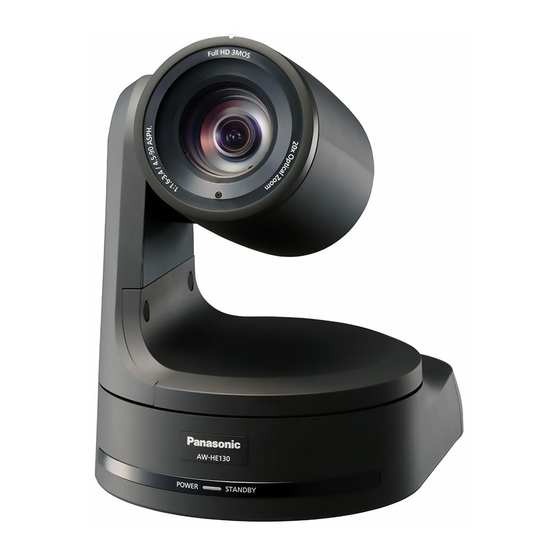
Page 23: Appearance
Appearance Unit: mm (inch) 125 (4-29/32) 90 (3-17/32) 180 (7-3/32) 234(9-3/16) - Page 24 Web Site: http://panasonic.net © Panasonic Corporation 2014...