Table of Contents
Advertisement
Quick Links
Download this manual
See also:
Service Manual
INSTRUCTION MANUAL
BEDIENUNGSANLEITUNG
MANUEL D'INSTRUCTIONS
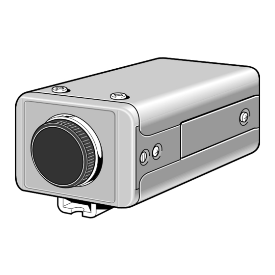
COLOUR CCD camera
CCD-Farbkamera
Caméra CCD COULEUR
CCD
About this manual
• Before installing and using the camera, please read this manual
carefully. Be sure to keep it handy for later reference.
• This manual gives basic connections and operating instructions for 2
PAL models (VCC-6592P, 6594P).
Über diese Bedienungsanleitung
• Lesen Sie bitte vor der Montage und dem Inbetriebnehmen der Kamera
zuerst diese Bedienungsanleitung sorgfältig durch und bewahren Sie
sie zum späteren Nachschlagen auf.
• In dieser Anleitung finden Sie die Anschlüsse und die Grundbedienung
für 2 PAL-Modelle (VCC-6592P und 6594P)
A propos de ce manuel
• Avant d'installer et d'utiliser la caméra, veuillez lire ce manuel
attentivement. Gardez-le à portée de main pour toute référence
ultérieure.
• Ce manuel couvre les branchements et instructions pour l'utilisation
de base pour 2 modèles de format PAL (VCC-6592P et 6594P).
2 PAL
VCC-6592P
VCC-6594P
VCC-6592P, 6594P
Advertisement
Table of Contents

Related Manuals for Sanyo VCC-6592P


Summary of Contents for Sanyo VCC-6592P
- Page 1 PAL models (VCC-6592P, 6594P). • Ce manuel couvre les branchements et instructions pour l’utilisation de base pour 2 modèles de format PAL (VCC-6592P et 6594P). Über diese Bedienungsanleitung • Lesen Sie bitte vor der Montage und dem Inbetriebnehmen der Kamera zuerst diese Bedienungsanleitung sorgfältig durch und bewahren Sie...
- Page 2 Sanyo Electric Co, Ltd. 1AC6P1P2424-- Printed in Japan L53H2, H4/XE (0901KPS-DSP)
-
Page 3: Table Of Contents
Not subject to interference from magnetic or electrostatic fields • Power supply: 24 V AC operation (VCC-6594P) ACCESSORIES 12 V DC operation (VCC-6592P) 1 Lens iris plug (4-pin)..............1 pc. Clamping core A: VCC-6594P...........2 pc. VCC-6592P...........3 pc. Clamping core B: VCC-6594P...........1 pc. -
Page 4: Precautions
Disconnect the power greasy smoke or steam, where the dampness may get too high, or cord immediately, and consult your dealer (or a Sanyo Authorized where there is a lot of dust. -
Page 5: Parts Names
Connect this connector to a device such as a VCR or monitor with a VIDEO IN connector. Power input terminal • VCC-6592P: 12 V DC input terminal (12 V DC, GND) • VCC-6594P: 24 V AC input terminal (AC 24 V, AC 24 V, GND) Y/C OUT connector (4 pin) Separate Y (luminance) and C (chroma) signals are output from this terminal. - Page 6 PARTS NAMES Lens mount cap The cap is installed to protect the lens mount section. Remove the lens mount cap before installing a lens (sold separately). Flange-back adjustment screw (FLANGE BACK ADJ.) Flange-back lock screw (FLANGE BACK LOCK) Camera installation bracket The bracket can be fixed at the top or bottom of the camera.
- Page 7 PARTS NAMES Lens iris output connector (LENS) This 4-pin connector is used to send the DC control signal and power supply to an auto-iris type lens. Camera setup section (under the cover) These settings are for when using a 1/3 inch CS mount DC (without EE internal amplifier) type lens. However, if due to installation conditions or environment the settings may need to be modified for best results (see "SETTINGS").
-
Page 8: Concerning Auto-Iris Lenses
ALC and LEVEL volume level controls are available on the lens for iris adjustments. (Set the A.I. LENS switch to the VIDEO position.) Compatible auto-iris lenses 1/3 inch Sanyo DC type lens VIDEO type lens VCL-CS8LY: Standard angle, f= 8 mm... -
Page 9: Mounting The Lens
MOUNTING THE LENS Please use a DC type auto-iris lens (sold separately). Check the lens mount Do not use a lens if the length “ ” is more than mm. That may damage the camera and prevent proper installation. C mount type lens Remove the lens mount cap from the camera. - Page 10 MOUNTING THE LENS Rewiring the lens cable in the lens iris plug Prepare the lens cable. Cut the cable at the plug, then remove approx. 8 mm of the cable sheath and strip about 2 mm from each wire. Install the lens iris plug. Solder the cable to the pins following the correct pin layout (refer to the table and illustrations), then close the plug cover.
-
Page 11: Connections
CONNECTIONS (VCC-6592P only) 12 V DC – (Video signal connections) 12 V DC connection : VIDEO IN Push to insert the cable 12 V DC input : VIDEO OUT Basic connection for monitoring or recording Insert the plug of this power cord into a wall outlet. - Page 12 CONNECTIONS (VCC-6592P only) 12 V DC – (Video signal connections) 12 V DC connection : VIDEO IN Push to insert the cable 12 V DC input : VIDEO OUT Connections to the camera Y/C OUT connector The POWER indicator (A) will light. Adjust the picture on the monitor using the Brightness and Contrast controls.
- Page 13 CONNECTIONS (VCC-6594P only) AC 24 V connection Push to insert the cable AC 24 V (Video signal connections) : VIDEO IN : VIDEO OUT Basic connection for monitoring or recording Insert the plug of this power cord into a wall outlet. The POWER indicator (A) will light.
-
Page 14: Settings
SETTINGS (VCC-6592P only) The illustration shows the factory default settings for the switches in the camera setup section. The camera settings are described on the assumption that a DC type auto iris lens is being used. If you are using a VIDEO type auto iris lens, be sure to read the Note which is given. - Page 15 SETTINGS (VCC-6594P only) The illustration shows the factory default settings for the switches in the camera setup section. The camera settings are described on the assumption that a DC type auto iris lens is being used. If you are using a VIDEO type auto iris lens, be sure to read the Note which is given.
- Page 16 SETTINGS Table A (switch 1 ~ 3) Electronic shutter settings and electronic iris settings 1/50(AI) 1/120 1/500 1/1000 1/2000 1/4000 1/10000 When all of these switches are down, electronic shutter (1/50 sec or auto iris setting) is enabled. The electronic shutter can be set to one of 7 speeds as shown in Table A.
- Page 17 SETTINGS (MULTI mode: 64 sections) Backlight compensation setting This camera has two different backlight compensation functions: Normally backlight compensation switch 6 (MULT) and 7 (CENT) are set to the down (OFF) position. Change the backlight compensation switch settings depending on the conditions. •...
- Page 18 SETTINGS White balance adjustment External sync adjustment (VBS) (VCC-6592P only) Normally the switch 8 (WB) is set to the down (ATW: auto white Connect the VBS signal output for the other camera to the VBS balance) position and the white balance is adjusted automatically. If a IN connector at the rear of this camera.
- Page 19 SETTINGS Lens iris adjustment Line phase adjustment (VCC-6594P only) If using a DC type auto-iris lens, you will need to set the LEVEL When using a camera switcher to connect 2 cameras or more to one (VR301) volume when shooting in the conditions described below. monitor, there may be a vertical roll of the images when switched.
-
Page 20: Troubleshooting
This camera is a precision instruments and if treated with care, will provide years of satisfactory performance. However, in the event of a problem, the owner is advised not to attempt to make repairs or open the cabinet. Servicing should always be referred to your dealer or Sanyo Authorized Service Centre. -
Page 21: Specifications
Video output level 1.0 Vp-p/75 ohms, composite Y/C signal outputs Y: Video; 0.7 Vp-p + sync; 0.3 Vp-p/75 ohms C: Burst; 0.3 Vp-p/75 ohms (VCC-6592P only) Video S/N ratio More than 48 dB Minimum required Approx. 0.3 lux with a F 1.2 lens (AGC, HI) illumination Approx. -
Page 22: Vcc-6592P
SPECIFICATIONS Dimensions 1/4”–20 UNC 12.6 (VCC-6592P) (VCC-6594P) 22.4 Features and specifications are subject to change without prior notice or obligations. English...