Lenovo ThinkServer TD230 Hardware Maintenance Manual
Machine types: 1027, 1029, 1039, and 1040
Hide thumbs
Also See for ThinkServer TD230:
- Installations- und benutzerhandbuch (162 pages) ,
- Guía del usuario y de instalación manual (162 pages) ,
- Manual d’installation et d’utilisation (160 pages)

Related Manuals for Lenovo ThinkServer TD230


Summary of Contents for Lenovo ThinkServer TD230
- Page 1 ThinkServer TD230 Hardware Maintenance Manual Machine Types: 1027, 1029, 1039, and 1040...
- Page 3 ThinkServer TD230 Hardware Maintenance Manual Machine Types: 1027, 1029, 1039, and 1040...
- Page 4 167 and the Warranty and Support Information document on the ThinkServer Documentation DVD. Eighth Edition (October 2011) © Copyright Lenovo 2010, 2011. LIMITED AND RESTRICTED RIGHTS NOTICE: If data or software is delivered pursuant a General Services Administration...
-
Page 5: Table Of Contents
Inspecting for unsafe conditions ..Guidelines for servicing electrical equipment . Removing the server cover ..Removing and reinstalling the front bezel .. - Page 6 Chapter 6. Parts listing, TD230 Types 1027, 1029, 1039, and 1040 ..Replaceable server components..Power cords ....
-
Page 7: Chapter 1. About This Manual
If Lenovo® installs a self-service CRU at your request, you will be charged for the installation. • Optional-service customer replaceable unit: You may install an optional-service CRU yourself or request Lenovo to install it, at no additional charge, under the type of warranty service that is designated for the server. - Page 8 Antes de utilizar el producto, asegúrese de leer y comprender las instrucciones de seguridad multilingües del DVD de documentación que se proporciona con el producto. Var noga med att läsa säkerhetsinstruktionerna på dokumentations-DVD-skivan som följer med produkten innan du börjar använda produkten. ThinkServer TD230 Hardware Maintenance Manual...
- Page 9 Be sure to read and understand all caution and danger statements in this document before you perform the procedures. Read and understand any additional safety information that comes with the server or optional device before you install, remove, or replace the device.
- Page 10 Some laser products contain an embedded Class 3A or Class 3B laser diode. Note the following. Laser radiation when open. Do not stare into the beam, do not view directly with optical instruments, and avoid direct exposure to the beam. ThinkServer TD230 Hardware Maintenance Manual...
- Page 11 Statement 4 ≥ 18 kg (39.7 lb) < 32 kg (70.5 lb) CAUTION: Use safe practices when lifting. Statement 5 CAUTION: The power control button on the device and the power switch on the power supply do not turn off the electrical current supplied to the device.
- Page 12 Overloading a branch circuit is potentially a fire hazard and a shock hazard under certain conditions. To avoid these hazards, ensure that your system electrical requirements do not exceed branch circuit protection requirements. Refer to the information that is provided with your device for electrical specifications. ThinkServer TD230 Hardware Maintenance Manual...
- Page 13 Statement 13 CAUTION: Make sure that the rack is secured properly to avoid tipping when the server unit is extended. Statement 14 CAUTION: Some accessory or option board outputs exceed Class 2 or limited power source limits and must be installed with appropriate interconnecting cabling in accordance with the national electric code.
-
Page 14: Important Information About Replacing Rohs Compliant Frus
Lenovo plans to transition to RoHS compliance well before the implementation date and expects its suppliers to be ready to support Lenovo's requirements and schedule in the EU. Products sold in 2005 will contain some RoHS compliant FRUs. The following statement pertains to these products and any product Lenovo produces containing RoHS compliant parts. - Page 15 RoHS compliant ThinkServer™ TD230 parts have unique FRU part numbers. Before or after June 2006, failed RoHS compliant parts must always be replaced using RoHS compliant FRUs, so only the FRUs identified as compliant in the system Hardware Maintenance Manual or direct substitutions for those FRUs can be used.
- Page 16 ThinkServer TD230 Hardware Maintenance Manual...
-
Page 17: Chapter 2. General Information
The following table provides information about the features and specifications of the server. Depending on the server model, some features might not be available, or some specifications might not apply. For information about your specific model, use the Setup Utility program. See “Using the Setup Utility program”... -
Page 18: Software Programs
Reliability, availability, and serviceability (hereafter referred to as RAS) are three important server design features. The RAS features help you to ensure the integrity of the data stored on the server, the availability of the server when you need it, and the ease with which you can diagnose and correct problems. - Page 19 • Advanced Desktop Management Interface (DMI) • Automatic memory downsizing on error detection • Automatic restart on non-maskable interrupt (NMI) • Availability of microcode level • Built-in, menu-driven setup, system configuration, and RAID configuration • Built-in monitoring for fan, temperature, and voltage •...
- Page 20 ThinkServer TD230 Hardware Maintenance Manual...
-
Page 21: Chapter 3. Diagnostics
Use the troubleshooting tables to find solutions to problems that have identifiable symptoms. If you have just added new software or a new optional device and the server is not working, complete the following steps before you use the troubleshooting tables: 1. -
Page 22: General Problems
The server stops responding Remove the hard disk drive that was being tested when the server stopped during the hard disk drive responding, and run the diagnostic test again. If the hard disk drive diagnostic test diagnostic test. -
Page 23: Keyboard, Mouse, Or Pointing-Device Problems
• All cables and cords are connected securely to the rear of the server and attached devices. • When the server is turned on, air is flowing from the fan grille. If there is no airflow, the fan is not working. This can cause the server to overheat and shut down. -
Page 24: Microprocessor Problems
• If a DIMM was disabled by the user or by POST, run the Setup Utility program and enable the DIMM. 3. Make sure that there is no memory mismatch when the server is at the minimum memory configuration. 4. Add one pair of DIMMs at a time, making sure that the DIMMs in each pair are matching. -
Page 25: Monitor Problems
1. Make sure that the monitor cables are firmly connected. 2. Try using a different monitor on the server, or try using the monitor that is being tested on a different server. 3. Run the diagnostic programs. If the monitor passes the diagnostic programs, the problem might be a video device driver. -
Page 26: Optional-Device Problems
(Trained service technician only) System board 1. Make sure that: • The device is designed for the server. For a list of the supported options for your server, go to http://www.lenovo.com/thinkserver. On the ThinkServer systems page, click Products ➙ Options. -
Page 27: Power Problems
If the problem remains, replace the operator information panel. 2. Make sure that: • The power cords are correctly connected to the server and to a working electrical outlet. • The type of memory that is installed is correct. -
Page 28: Serial Port Problems
A serial device does not work. ThinkServer TD230 Hardware Maintenance Manual 5. If you just installed an optional device, remove it, and restart the server. If the server now starts, you might have installed more devices than the power supply supports. -
Page 29: Software Problems
• The correct USB device driver is installed. • The operating system supports USB devices. • A standard PS/2 keyboard or mouse is not connected to the server. If it is, a USB keyboard or mouse will not work during the POST. -
Page 30: Solving Ethernet Controller Problems
• Check the LAN activity LEDs on the rear of the server. The LAN activity LED is lit when data is active on the Ethernet network. If the LAN activity LED is off, make sure that the hub and network are operating and that the correct device drivers are installed. -
Page 31: Event Logs
1. Turn off the server. 2. Make sure that the server is cabled correctly. 3. Remove or disconnect the following devices, one at a time, until you find the failure. Turn on the server and reconfigure it each time. • Any external devices •... -
Page 32: Diagnostic Leds On The Front Panel And The System Board
Identifying the diagnostic LEDs on the front panel and the system board is a very important method for diagnosing server problems. See “Front view” on page 27 and “Locating diagnostic LEDs on the system board” on page 35 for detailed information. -
Page 33: Chapter 4. Locating Parts, Controls, Leds, And Connectors
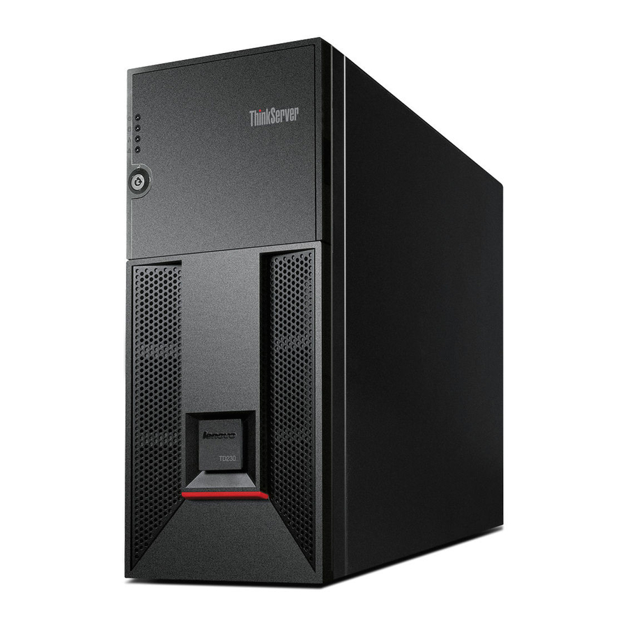
This chapter provides information to help you locate your server parts, controls, light-emitting diodes (LEDs), and connectors. Front view Figure 1 “Front view of the server” on page 27 shows the LEDs and parts on the front of the server. Figure 1. Front view of the server Power LED... - Page 34 Figure 2. Opening the front door Figure 3 “Front view of the server (with the front door open)” on page 29 shows the controls, LEDs, connectors, and other parts on the front panel after you open the front door. ThinkServer TD230 Hardware Maintenance Manual...
- Page 35 Ethernet status LED System status LED Power button The following table describes the various meanings of the status LEDs on the front panel of your server. Table 2. Meanings of the status LEDs on the front panel State Power LED...
-
Page 36: Rear View
Ethernet status Blinking System status Blinking Rear view Figure 4 “Rear view of the server” on page 31 shows the locations of the connectors and parts on the rear of the server. ThinkServer TD230 Hardware Maintenance Manual Color Green The server is linked to a local area network (LAN). -
Page 37: Hot-Swap Hard Disk Drive Status Leds
VGA monitor connector USB connectors (4) Hot-swap hard disk drive status LEDs For server models with hot-swap hard disk drives, each hot-swap hard disk drive also has two status LEDs on the front. Figure 5. Hot-swap hard disk drive status LEDs... -
Page 38: Leds For The Ethernet Connectors
Figure 6 “Server component locations (side view without the server cover)” on page 33 shows the locations of the major components in your server. To remove the server cover and gain access to the inside of the server, see “Removing the server cover” on page 43. -
Page 39: Locating Parts On The System Board
Memory slots for microprocessor 2 (some slots might with installed memory modules) Note: * denotes that this illustration only shows the server models with four hot-swap hard disk drives. There are also server models that support up to five non-hot-swap hard disk drives. - Page 40 Microprocessor 2 heat sink and fan assembly connector System fan 1 connector Memory slot (CPU2 DIMM CHD2) Memory slot (CPU2 DIMM CHD1) ThinkServer TD230 Hardware Maintenance Manual SATA connector 0 SATA connector 1 SATA connector 2 SATA connector 3 SATA connector 4 Internal dual-port USB 2.0 connector (ports 0-1)
-
Page 41: Locating Diagnostic Leds On The System Board
There are several jumper blocks on the system board that can be used to configure, recover, or enable/disable specific features of the server system board. Figure 9 “Jumper blocks on the system board” on page 36 shows the status of the jumper blocks on the system board. - Page 42 These pins should have a jumper in place for normal system operation (default). Password Pins 2-3 If these pins are jumpered, administrator and user passwords will be cleared on the clear next reset. These pins should not be jumpered for normal operation. ThinkServer TD230 Hardware Maintenance Manual Description...
-
Page 43: Locating Connectors On The Hot-Swap Hard Disk Drive Backplanes
Note: Before clearing the CMOS, turn off the server and disconnect the power cord. Move the jumper from pins 1-2 to pins 2-3. Wait more than five minutes; then, move the jumper back to the normal position (pins 1-2 is short circuited) to clear CMOS. - Page 44 ThinkServer TD230 Hardware Maintenance Manual...
-
Page 45: Chapter 5. Replacing Frus
• If you must turn on the server while the server cover is removed, make sure that no one is near the server and that no tools or other objects have been left inside the server. -
Page 46: System Reliability Guidelines
• For a list of supported optional devices for the server, go to http://www.lenovo.com/thinkserver. • When working inside the server, you might find some tasks easier if you lay the server on its side. You might need to first pivot the foot stands inward and then lay the computer on its side. -
Page 47: Working Inside The Server With The Power On
This section contains information for trained service technicians. Inspecting for unsafe conditions Use the information in this section to help you identify potential unsafe conditions in a Lenovo product that you are working on. Each Lenovo product, as it was designed and manufactured, has required safety items to protect users and service technicians from injury. -
Page 48: Guidelines For Servicing Electrical Equipment
4. Remove the cover. 5. Check for any obvious non-Lenovo alterations. Use good judgment as to the safety of any non-Lenovo alterations. 6. Check inside the server for any obvious unsafe conditions, such as metal filings, contamination, water or other liquid, or signs of fire or smoke damage. -
Page 49: Removing The Server Cover
Removing the server cover Attention: Do not open your server or attempt any repair before reading and understanding the Safety Information and the Warranty and Support Information on the ThinkServer Documentation DVD that came with your product, and “Guidelines” on page 39. To obtain a copy of the publications, go to: http://www.lenovo.com/support... - Page 50 4. Loosen the two thumbscrews attached on the rear of the server cover and then slide the server cover to the rear. Notes: a. The two thumbscrews are securely installed and you need to use a tool, for example a screw driver, to loosen the thumbscrews.
-
Page 51: Removing And Reinstalling The Front Bezel
To remove and reinstall the front bezel, do the following: 1. Remove all media from the drives and turn off all attached devices and the server. Then, disconnect all power cords from electrical outlets and disconnect all cables that are connected to the server. -
Page 52: Locking Or Unlocking The Hard Disk Drive Side Door
Locking or unlocking the hard disk drive side door Attention: Do not open your server or attempt any repair before reading and understanding the Safety Information and the Warranty and Support Information on the ThinkServer Documentation DVD that came with your product, and “Guidelines”... - Page 53 The hard disk drive side door of the server is unlocked when shipped from the factory. You can open the side door to view the hot-swap hard disk drive LED status, install a new hard disk drive, and remove or replace a failing hard disk drive.
- Page 54 2. Rotate the plastic latch of the side door to the closed position. Then, close the side door until it snaps into position. The side door is locked and cannot be opened when you press the blue button. Figure 15. Locking the side door ThinkServer TD230 Hardware Maintenance Manual...
-
Page 55: Installing, Removing, Or Replacing Optional Hardware Devices
Reinstall the server cover. See “Installing the server cover” on page 122. The side door is unlocked and you can open the side door by pressing the blue button on it, as shown in Figure 14 “Opening the side door” on page 47. -
Page 56: Installing A Memory Module
To install a memory module, do the following: 1. Remove all media from the drives and turn off all attached devices and the server. Then, disconnect all power cords from electrical outlets and disconnect all cables that are connected to the server. -
Page 57: Removing A Memory Module
Removing a memory module Attention: Do not open your server or attempt any repair before reading and understanding the Safety Information and the Warranty and Support Information on the ThinkServer Documentation DVD that came with your product, and “Guidelines” on page 39. To obtain a copy of the publications, go to: http://www.lenovo.com/support... -
Page 58: Removing Or Installing Internal Drives
• For a list of the supported hard disk drives for your server, go to http://www.lenovo.com/thinkserver. On the ThinkServer systems page, click Products ➙ Options ➙ ThinkServer Hard Drives. -
Page 59: Removing The Optical Drive
To remove the optical drive, do the following: 1. Remove all media from the drives and turn off all attached devices and the server. Then, disconnect all power cords from electrical outlets and disconnect all cables that are connected to the server. -
Page 60: Installing The Optical Drive
Installing the optical drive Attention: Do not open your server or attempt any repair before reading and understanding the Safety Information and the Warranty and Support Information on the ThinkServer Documentation DVD that came with your product, and “Guidelines” on page 39. To obtain a copy of the publications, go to: http://www.lenovo.com/support... - Page 61 Appareil A Laser de Classe 1 2. Remove all media from the drives and turn off all attached devices and the server. Then, disconnect all power cords from electrical outlets and disconnect all cables that are connected to the server.
- Page 62 Figure 24. Connecting the optical drive cables 9. To complete the installation, go to “Completing the parts replacement” on page 122. ThinkServer TD230 Hardware Maintenance Manual to the rear of the new optical drive and the other end to an...
- Page 63 To remove a hot-swap hard disk drive, do the following: Note: You do not have to turn off the server when removing a hot-swap hard disk drive. However, if you have locked the side door, you must turn off the server, disconnect all power cords, and remove the server cover when you want to remove, install, or replace any hard disk drives.
- Page 64 2. Locate the hot-swap hard disk drive you want to remove. Then, press the blue release button rotate the handle of the hard disk drive bracket to the open position. Figure 26. Opening the handle of the hot-swap hard disk drive bracket ThinkServer TD230 Hardware Maintenance Manual...
- Page 65 3. Grasp the handle and pull the hard disk drive bracket with the hard disk drive out of the drive bay. Figure 27. Removing the hot-swap hard disk drive bracket with the hard disk drive Chapter 5 Replacing FRUs...
- Page 66 Notes: 1. You do not have to turn off the server for the installation of a hot-swap hard disk drive. However, if you have locked the side door, you must turn off the server, disconnect all power cords, and remove the server cover when you want to remove, install, or replace any hard disk drives.
- Page 67 1. Press the blue button to open the side door. Figure 29. Opening the side door Chapter 5 Replacing FRUs...
- Page 68 2. Locate a hot-swap hard disk drive bay that you want to install the drive. Then, press the blue release button and rotate the handle of the hard disk drive bracket to the open position. Figure 30. Opening the handle of the hot-swap hard disk drive bracket ThinkServer TD230 Hardware Maintenance Manual...
- Page 69 4. Remove the plastic drive bay filler and save it for future use. Note: The EMI integrity and cooling of the server are protected by having all drive bays and PCI card slots covered or occupied. When you install a drive or PCI card, save the EMC shield or drive bay filler from the drive bay or save the PCI card slot cover in the event that you later remove the device.
- Page 70 7. Keep the handle of the hot-swap hard disk drive bracket fully open and then slide the bracket with the hard disk drive into the drive bay until it cannot be pushed in anymore. Figure 33. Sliding the hot-swap hard disk drive bracket with the hard disk drive into the bay ThinkServer TD230 Hardware Maintenance Manual...
-
Page 71: Removing A Non-Hot-Swap Hard Disk Drive
9. Check the hard disk drive status LEDs to make sure that the hard disk drive is operating correctly. You might have to restart the server for the newly installed drive to be recognized. If the amber hard disk drive status LED is lit continuously, this indicates that the hard disk drive is faulty and must be replaced;... - Page 72 To remove a non-hot-swap hard disk drive, do the following: 1. Remove all media from the drives and turn off all attached devices and the server. Then, disconnect all power cords from electrical outlets and disconnect all cables that are connected to the server.
- Page 73 3. Locate the non-hot-swap hard disk drive you want to remove and disconnect the power cable and the signal cable from the hard disk drive. Then, pull the handle of the hard disk drive bracket to slide the bracket with the hard disk drive out of the drive bay. Figure 36.
-
Page 74: Installing A Non-Hot-Swap Hard Disk Drive
Installing a non-hot-swap hard disk drive Attention: Do not open your server or attempt any repair before reading and understanding the Safety Information and the Warranty and Support Information on the ThinkServer Documentation DVD that came with your product, and “Guidelines”... - Page 75 1. Remove all media from the drives and turn off all attached devices and the server. Then, disconnect all power cords from electrical outlets and disconnect all cables that are connected to the server. 2. Press the blue button to open the side door.
- Page 76 4. Remove the plastic drive bay filler and save it for future use. Note: The EMI integrity and cooling of the server are protected by having all drive bays and PCI card slots covered or occupied. When you install a drive or PCI card, save the EMC shield or drive bay filler from the drive bay or save the PCI card slot cover in the event that you later remove the device.
- Page 77 • If you want to secure the hard disk drive in the bracket by screws, align the screw holes in both sides of the hard disk drive with the corresponding holes in the bracket. Then, install the four screws to secure the hard disk drive in the bracket.
-
Page 78: Installing Or Removing A Pci Card
This section provides instructions on how to install or remove a PCI card. The EMI integrity and cooling of the server are protected by having all drive bays and PCI card slots covered or occupied. When you install a drive or PCI card, save the EMC shield or drive bay filler from the drive bay or save the PCI card slot cover in the event that you later remove the device. - Page 79 Note: Use any documentation that came with the PCI card and follow those instructions in addition to the instructions in this section. 1. Remove all media from the drives and turn off all attached devices and the server. Then, disconnect all power cords from electrical outlets and disconnect all cables that are connected to the server.
-
Page 80: Removing A Pci Card
Note: Use any documentation that came with the PCI card and follow those instructions in addition to the instructions in this section. 1. Remove all media from the drives and turn off all attached devices and the server. Then, disconnect all power cords from electrical outlets and disconnect all cables that are connected to the server. -
Page 81: Installing Or Removing The Ethernet Card
Installing the Ethernet card Attention: Do not open your server or attempt any repair before reading and understanding the Safety Information and the Warranty and Support Information on the ThinkServer Documentation DVD that came with your product, and “Guidelines” on page 39. To obtain a copy of the publications, go to: http://www.lenovo.com/support... -
Page 82: Removing The Ethernet Card
To install the Ethernet card, do the following: 1. Remove all media from the drives and turn off all attached devices and the server. Then, disconnect all power cords from electrical outlets and disconnect all cables that are connected to the server. -
Page 83: Installing Or Removing The Thinkserver Raid 100 Upgrade Key For Advanced Raid
Advanced RAID (hereafter called the RAID 5 key). The RAID 5 key is an activation key, which you can install on the system board to enable the RAID 5 configuration function of the onboard SATA RAID for your server. Installing the RAID 5 key... - Page 84 Perform the following procedure at an ESD-safe workstation. 1. Remove all media from the drives and turn off all attached devices and the server. Then, disconnect all power cords from electrical outlets and disconnect all cables that are connected to the server.
-
Page 85: Installing Or Removing The Thinkserver Raid 500 Upgrade Key For Advanced Raid
Installing the TR 500 key Attention: Do not open your server or attempt any repair before reading and understanding the Safety Information and the Warranty and Support Information on the ThinkServer Documentation DVD that came with your product, and “Guidelines” on page 39. To obtain a copy of the publications, go to: http://www.lenovo.com/support... - Page 86 1. Remove all media from the drives and turn off all attached devices and the server. Then, disconnect all power cords from electrical outlets and disconnect all cables that are connected to the server. 2. Remove the server cover. See “Removing the server cover” on page 43.
-
Page 87: Installing Or Removing The Thinkserver Remote Management Module 3
3. Lay the server on its side for easier operation. 4. Remove the ThinkServer RAID 500 Adapter. See “Removing the RAID card” on page 88 and follow those instructions to remove the ThinkServer RAID 500 Adapter. 5. Remove the TR 500 key from the ThinkServer RAID 500 Adapter. -
Page 88: Installing The Rmm
“Guidelines” on page 39. To obtain a copy of the publications, go to: http://www.lenovo.com/support This section provides instructions on how to install the RMM3 in your server. You can get an increased level of manageability over the basic server management available to the system board by installing the RMM3 option. - Page 89 7. Make a note of the Media Access Controller (MAC) address of the RMM3. This information is on a label attached to the RMM3 and might be used later for several software configurations. Keeping a record at this moment might eliminate the needs to reopen the server cover later. Chapter 5...
- Page 90 RMM3 to the slot bracket. The extra one is a backup screw. b. For easier operation, you might need to attach a plastic standoff that came with the option package to each screw before installing the screw. Figure 52. Installing the RMM3 on the slot bracket ThinkServer TD230 Hardware Maintenance Manual...
- Page 91 9. Insert the slot bracket with RMM3 into the position for the PCI card slot bracket you have removed. Then, secure the slot bracket with RMM3 in place by installing the screw that you have removed in step 5 on page 83. Figure 53.
- Page 92 Removing the RMM3 Attention: Do not open your server or attempt any repair before reading and understanding the Safety Information and the Warranty and Support Information on the ThinkServer Documentation DVD that came with your product, and “Guidelines” on page 39. To obtain a copy of the publications, go to: http://www.lenovo.com/support...
- Page 93 To remove the RMM3, do the following: 1. Remove all media from the drives and turn off all attached devices and the server. Then, disconnect all power cords from electrical outlets and disconnect all cables that are connected to the server. Wait three to five minutes to let the server cool before removing the server cover.
-
Page 94: Installing, Removing, Or Replacing Hardware Devices
To remove the RAID card, do the following: 1. Remove all media from the drives and turn off all attached devices and the server. Then, disconnect all power cords from electrical outlets and disconnect all cables that are connected to the server. - Page 95 To install the RAID card, do the following: 1. Remove all media from the drives and turn off all attached devices and the server. Then, disconnect all power cords from electrical outlets and disconnect all cables that are connected to the server.
- Page 96 Installing the ThinkServer 8708EM2 RAID Adapter Attention: Do not open your server or attempt any repair before reading and understanding the Safety Information and the Warranty and Support Information on the ThinkServer Documentation DVD that came with your product, and “Guidelines”...
- Page 97 1. Remove all media from the drives and turn off all attached devices and the server. Then, disconnect all power cords from electrical outlets and disconnect all cables that are connected to the server. 2. Remove the server cover. See “Removing the server cover” on page 43.
- Page 98 2. The battery card assembly option kit contains a user guide, the battery card assembly, and three Phillips-head screws. Do not remove the battery card assembly from the antistatic shipping container until you are ready to install it. When you remove the battery card assembly from your server, place it in its original container.
- Page 99 1. Note the top view and bottom view of the battery card assembly. Then, insert the battery pack harness connector into the J4 battery pack harness connector on the backside of the battery card assembly. For more information, refer to the following illustrations. Figure 58.
-
Page 100: Connecting The Mini Sas Cable
Your server comes with an 880 mm (34.65 inches) mini SAS cable with four mini SAS connectors. The four SAS connectors of the cable connect to the four SAS connectors on the hot-swap hard disk drive backplanes. - Page 101 Figure 61. SAS connectors on the hot-swap hard disk drive backplanes SATA/SAS signal connector 2 SATA/SAS signal connector 3 When connecting the ThinkServer RAID 500 Adapter to the hot-swap hard disk drive backplanes using the mini SAS cable, connect the mini SAS connector , and to the SAS connectors 0, 1, 2, and 3 on the hot-swap hard disk drive backplanes.
-
Page 102: Removing Or Installing The Heat Sink And Fan Assembly
Hazardous moving parts. Keep fingers and other body parts away. CAUTION: The heat sink and fan assembly might be very hot. Turn off the server and wait three to five minutes to let the server cool before removing the server cover. - Page 103 To remove the heat sink and fan assembly, do the following: 1. Remove all media from the drives and turn off all attached devices and the server. Then, disconnect all power cords from electrical outlets and disconnect all cables that are connected to the server.
- Page 104 7. If you are instructed to return the removed heat sink and fan assembly to the manufacturer, follow all packaging instructions and use any packaging materials that are supplied to you for shipping. ThinkServer TD230 Hardware Maintenance Manual on the bottom of it.
- Page 105 Hazardous moving parts. Keep fingers and other body parts away. CAUTION: The heat sink and fan assembly might be very hot. Turn off the server and wait three to five minutes to let the server cool before removing the server cover.
- Page 106 4. Touch the static-protective package that contains the heat sink and fan assembly to any unpainted surface on the outside of the server. Then, remove the heat sink and fan assembly from the package. Note: When handling the heat sink and fan assembly, do not touch the thermal grease on the bottom of it.
-
Page 107: Removing Or Installing A Front Fan
Removing a front fan Attention: Do not open your server or attempt any repair before reading and understanding the Safety Information and the Warranty and Support Information on the ThinkServer Documentation DVD that came with your product, and “Guidelines” on page 39. To obtain a copy of the publications, go to: http://www.lenovo.com/support... - Page 108 To remove a front fan, do the following: 1. Remove all media from the drives and turn off all attached devices and the server. Then, disconnect all power cords from electrical outlets and disconnect all cables that are connected to the server.
- Page 109 Installing a front fan Attention: Do not open your server or attempt any repair before reading and understanding the Safety Information and the Warranty and Support Information on the ThinkServer Documentation DVD that came with your product, and “Guidelines” on page 39. To obtain a copy of the publications, go to: http://www.lenovo.com/support...
- Page 110 To install a front fan, do the following: 1. Remove all media from the drives and turn off all attached devices and the server. Then, disconnect all power cords from electrical outlets and disconnect all cables that are connected to the server.
-
Page 111: Removing Or Installing The Rear Fan
Notes: a. The new front fan will have four new rubber mounts attached. b. If two microprocessors are installed in your server, you can install two front fans, one for microprocessor 1 and the other for microprocessor 2. c. You might also need to pull the rubber mounts through the holes from the other side to secure the front fan in place. -
Page 112: Removing The Rear Fan
To remove the rear fan, do the following: 1. Remove all media from the drives and turn off all attached devices and the server. Then, disconnect all power cords from electrical outlets and disconnect all cables that are connected to the server. - Page 113 Installing the rear fan Attention: Do not open your server or attempt any repair before reading and understanding the Safety Information and the Warranty and Support Information on the ThinkServer Documentation DVD that came with your product, and “Guidelines” on page 39. To obtain a copy of the publications, go to: http://www.lenovo.com/support...
- Page 114 To install the rear fan, do the following: 1. Remove all media from the drives and turn off all attached devices and the server. Then, disconnect all power cords from electrical outlets and disconnect all cables that are connected to the server.
-
Page 115: Removing Or Installing The Microprocessor
3. Place the rear fan on the chassis so that the four rubber mounts are aligned with the corresponding holes in the chassis. Then, push the rubber mounts through the holes. Notes: a. The new rear fan will have four new rubber mounts attached. b. -
Page 116: Removing The Microprocessor
This section provides instructions on how to remove the microprocessor. CAUTION: The heat sink and fan assembly might be very hot. Turn off the server and wait three to five minutes to let the server cool before removing the server cover. -
Page 117: Installing The Microprocessor
This section provides instructions on how to install the microprocessor. CAUTION: The heat sink and fan assembly might be very hot. Turn off the server and wait three to five minutes to let the server cool before removing the server cover. - Page 118 Figure 76. Removing the microprocessor socket cover 8. Remove the new microprocessor from the protective cover that protects the gold contacts on the bottom of the new microprocessor. ThinkServer TD230 Hardware Maintenance Manual...
-
Page 119: Replacing The System Board Battery
Replacing the system board battery Attention: Do not open your server or attempt any repair before reading and understanding the Safety Information and the Warranty and Support Information on the ThinkServer Documentation DVD that came with your product, and “Guidelines” on page 39. To obtain a copy of the publications, go to: http://www.lenovo.com/support... -
Page 120: Removing Or Installing The System Board
To replace the system board battery, do the following: 1. Remove all media from the drives and turn off all attached devices and the server. Then, disconnect all power cords from electrical outlets and disconnect all cables that are connected to the server. - Page 121 This section provides instructions on how to remove the system board. CAUTION: The heat sink and fan assembly might be very hot. Turn off the server and wait three to five minutes to let the server cool before removing the server cover.
- Page 122 15. If you are instructed to return the failing system board, follow all packaging instructions, and use any packaging materials that are supplied to you for shipping. ThinkServer TD230 Hardware Maintenance Manual of the...
-
Page 123: Installing The System Board
CAUTION: The heat sink and fan assembly might be very hot. Turn off the server and wait three to five minutes to let the server cool before removing the server cover. To install a system board after a failing system board is removed, do the following: 1. -
Page 124: Replacing The Power Supply Assembly
To replace the power supply assembly, do the following: 1. Remove all media from the drives and turn off all attached devices and the server. Then, disconnect all power cords from electrical outlets and disconnect all cables that are connected to the server. - Page 125 6. Remove the four screws in the rear of the chassis that secure the power supply assembly and the screw that secures the small metal clip, which holds the power supply assembly in place. Then, remove the metal clip to release the power supply assembly. Figure 82.
- Page 126 Figure 83. Removing the power supply assembly 8. Place the new power supply assembly into the chassis so that the four screw holes in the new power supply assembly are aligned with the corresponding holes in the rear of the chassis. ThinkServer TD230 Hardware Maintenance Manual...
- Page 127 9. Install the four screws to secure the new power supply assembly and install the metal clip to hold the new power supply assembly in place. Then, install the screw to secure the metal clip. Note: Use only screws provided by Lenovo. Figure 84. Installing the power supply assembly...
-
Page 128: Completing The Parts Replacement
Figure 85. Holes in the chassis for cable routing 11. For server models with hot-swap hard disk drives, connect the power cables to the power connectors on the hot-swap hard disk drive backplanes. See “Locating connectors on the hot-swap hard disk drive backplanes”... -
Page 129: Connecting The Cables
Updating the server configuration When you turn on the server for the first time after you add or remove a device, you might receive a message to notify you that the configuration has been changed. The Setup Utility program starts automatically so that you can save the new configuration settings. -
Page 130: Turning Off The Server
If the server has an optional RAID controller and you have installed or removed a hard disk drive, see the documentation that comes with the RAID controller for information about reconfiguring the disk arrays. Turning off the server When you turn off the server and leave it connected to ac power, the server can respond to requests to the service processor, such as a remote request to turn on the server. -
Page 131: Chapter 6. Parts Listing, Td230 Types 1027, 1029, 1039, And 1040
Chapter 6. Parts listing, TD230 Types 1027, 1029, 1039, and 1040 The following replaceable components are available for the ThinkServer TD230 Types 1027, 1029, 1039, and 1040 servers. To check for an updated parts listing on the Web, do the following: 1. - Page 132 • Optional-service customer replaceable unit: You may install an optional-service CRU yourself or request Lenovo to install it, at no additional charge, under the type of warranty service that is designated for your server. • Field replaceable unit (FRU): FRUs must be installed only by trained service technicians.
- Page 133 Screw kit (models CTO, all models) Non-hot-swap hard disk drive tray (SATA) (models CTO, all models) CRU part number (Tier 1) 46U3570 46U3591 Chapter 6 Parts listing, TD230 Types 1027, 1029, 1039, and 1040 FRU part CRU part number number (Tier 2) 71Y9037 71Y9039 71Y9045...
- Page 134 Intel Remote Management Module 3 (models CTO) Lenovo RDX drive bay (models CTO) Lenovo RDX cables (models CTO) Lenovo RDX 160 GB cartridge (models CTO) Lenovo RDX 320 GB cartridge (models CTO) Lenovo RDX 500 GB cartridge (models CTO) Documentation DVD...
- Page 135 CRU part number (Tier 1) 46U3442 46U3443 46U3193 46U3191 71Y5543 46U3206 46U3228 46U3197 Chapter 6 Parts listing, TD230 Types 1027, 1029, 1039, and 1040 FRU part CRU part number number (Tier 2) 03X3635 CRU part FRU part number number (Tier 2)
- Page 136 1366 sockets (models CTO 13U 13G 14G 15U 15G 16U 16G 17U 17G 18U 18G 19U 19G 1AU 1AG 1BU 1BG) Processor heat sink GBM 40/80/95 W (models CTO, all models) ThinkServer TD230 Hardware Maintenance Manual FRU part CRU part CRU part...
- Page 137 67Y1424 67Y1425 67Y1421 67Y1422 67Y1423 90Y1460 91Y1652 03X3602 90Y1174 90Y1176 90Y1177 90Y1178 90Y1180 Chapter 6 Parts listing, TD230 Types 1027, 1029, 1039, and 1040 FRU part CRU part number number (Tier 2) 46U3231 03X3605 90Y1611 46U3579 46U3580 46U3582 46U3590 46U3588...
- Page 138 Hard disk drive, 300 GB SAS - 15000 rpm, 3 Gb/s, 32 MB Cache, 3.5" (models CTO) Hard disk drive, 450 GB SAS - 15000 rpm, 36 Gb/s, 32 MB Cache, 3.5" (models CTO) ThinkServer TD230 Hardware Maintenance Manual FRU part CRU part CRU part...
- Page 139 Microprocessor, Intel Xeon E5675 - 6 Core 3.06 GHz - 6.4QPI, 12 MB Cache, DDR3-1333, 95 W (models CTO) CRU part number (Tier 1) 46U3228 46U3197 Chapter 6 Parts listing, TD230 Types 1027, 1029, 1039, and 1040 FRU part CRU part number number (Tier 2) 46U3400 03X3623...
- Page 140 Intel Remote Management Module 3 (models CTO 13U 13G) Lenovo RDX drive bay (models CTO) Lenovo RDX cables (models CTO) Lenovo RDX 160 GB cartridge (models CTO) Lenovo RDX 320 GB cartridge (models CTO) Lenovo RDX 500 GB cartridge (models CTO) Documentation DVD (models CTO)
- Page 141 90Y1197 90Y1182 CRU part number (Tier 1) 46U3442 46U3443 46U3193 46U3191 71Y5543 46U3206 Chapter 6 Parts listing, TD230 Types 1027, 1029, 1039, and 1040 FRU part CRU part number number (Tier 2) 67Y1430 03X3635 FRU part CRU part number number...
- Page 142 4.8QPI, 4 MB Cache, DDR3-800, 80 W (models CTO 13U 13G 14U 14G) 6, 10 Microprocessor, Intel Xeon E5606 - Quad Core 2.13 GHz - 4.8QPI, 4 MB Cache, DDR3-800, 80 W (models CTO) ThinkServer TD230 Hardware Maintenance Manual FRU part CRU part CRU part number...
- Page 143 Lenovo RDX drive bay (models CTO) Lenovo RDX cables (models CTO) CRU part number (Tier 1) 46U3570 46U3591 46U3584 67Y1424 67Y1425 Chapter 6 Parts listing, TD230 Types 1027, 1029, 1039, and 1040 FRU part CRU part number number (Tier 2) 03X3647 03X3648 03X3649 03X3650 03X3651...
-
Page 144: Power Cords
(models CTO) Power cords For your safety, Lenovo provides a power cord with a grounded attachment plug to use with this Lenovo product. To avoid electrical shock, always use the power cord and plug with a properly grounded outlet. Lenovo power cords used in the United States and Canada are listed by Underwriter’s Laboratories (UL) and certified by the Canadian Standards Association (CSA). - Page 145 The cord set should have the appropriate safety approvals for the country in which the equipment will be installed. Lenovo power cords for a specific country or region are usually available only in that country or region. Table 11. Power cords, Type 1027...
- Page 146 South Africa (models CTO) 41R3224 Hong Kong, UK, Ireland, Singapore, Malaysia, Brunei (models CTO) 41R3228 Switzerland (models CTO) 41R3232 Italy (models CTO) 41R3236 Israel (models CTO) 41R3256 China (models CTO) 41R3260 Korea (models CTO) 41R3270 Brazil (models CTO) ThinkServer TD230 Hardware Maintenance Manual...
- Page 147 Table 14. Power cords, Type 1040 (continued) Lenovo power cord part number Used in these countries and regions 41R3278 Taiwan (models CTO) 43N9029 Thailand (models CTO) Chapter 6 Parts listing, TD230 Types 1027, 1029, 1039, and 1040...
- Page 148 ThinkServer TD230 Hardware Maintenance Manual...
-
Page 149: Chapter 7. Configuring The Server
BIOS version on your server is later than S5500.86B.01.00.0059.082320111421 or the BIOS is built later than August 26th, 2011. To update the BIOS version on your server, go to http://www.lenovo.com/support, and then follow the instructions on the screen to download and install the appropriate BIOS version. -
Page 150: Starting The Setup Utility Program
Turn on the server and the POST runs automatically. You will then see the logo screen. The POST is a set of tests and procedures that are performed each time you turn on your server. 2. Press F2 as soon as you see the logo screen. The Setup Utility program opens. If you have set an administrator password, you must type the administrator password to access the full Setup Utility program menu. - Page 151 Set the security parameters. See Table 27 “Items under the Security menu” on page 148. Set the server system management parameters. See Table 28 “Items under the Server Management menu” on page 148. Set the boot parameters. See Table 29 “Items under the Boot Options menu”...
- Page 152 Table 20. Submenus under the Memory Configuration Item Total Memory Effective Memory Current Configuration Current Memory Speed Memory RAS and Performance Configuration ThinkServer TD230 Hardware Maintenance Manual Option Disabled / [Enabled] Disabled / [Enabled] Disabled / [Enabled] Disabled / [Enabled] [Disabled] / Enabled...
- Page 153 Enable or disable the I/O port. This function is for the operating system that does not support on legacy USB devices. Set the USB device as non-bootable device. Set the device reset timeout. Enable or disable the USB 2.0 support. Chapter 7 Configuring the server...
- Page 154 Assert NMI on SERR Assert NMI on PERR Resume on AC Power Loss Clear System Event Log ThinkServer TD230 Hardware Maintenance Manual [Disabled] / Enabled [Disabled] / Enabled [Enabled] / Disabled [Disabled] / Enabled (If enable this option, the system can support the add-in graphics card.)
-
Page 155: Using Passwords
• If you want to return to the default settings, press F9 or select Exit ➙ Load Default Values. Using passwords By using the Setup Utility program, you can set a password to prevent unauthorized access to your server and data. The following options are available to help you set an administrator password or a user password: •... -
Page 156: Raid Controllers
• Created a RAID response file that can be used to configure RAID controllers on similarly ThinkServer TD230 Hardware Maintenance Manual Description Location EasyStartup DVD Where to find more information “Using the ThinkServer EasyStartup program”... -
Page 157: Using The Thinkserver Easystartup Program
• Support for multiple operating systems • Installs the operating system and device drivers in an unattended mode to save time • Creates a reuseable response file that can be used with similarly configured Lenovo servers to make future installations even faster. -
Page 158: Before You Use The Easystartup Dvd
English. You will then see one or more reminders about configuring storage devices, and then you will be presented with the Lenovo License Agreement. Read the license agreement carefully. You must agree with terms in order to continue. -
Page 159: Configuring Raid
As you configure each controller you will be given the option to save the RAID configuration settings to a RAID response file, which you can use on other similarly configured Lenovo servers. This method satisfies most users' needs. Typical operating system installation When you select Install operating system, you will be prompted for information required for the installation. -
Page 160: Starting The Intel Embedded Server Raid Technology Ii Program
• The Check Consistency item is for consistency check. Creating a RAID volume This section provides instructions on how to create a RAID volume by using the Intel Embedded Server RAID Technology II program. There are three methods to create a RAID volume: •... -
Page 161: Initializing The Raid Volume
To delete the RAID volume, do the following: 1. Select Management ➙ Configure from the main menu and press Enter. The Configuration Menu opens. 2. Select Clear Configuration. Virtual Drive(s) Configured Size #Stripes 73664 MB Chapter 7 StripSz Status 64 KB ONLINE Configuring the server... -
Page 162: Rebuilding The Raid Volume
If you are connecting the hot-swap hard disk drive backplanes to the system board, use the 790 mm (31.70 inches) SATA cable assembly that comes with your server. Connect one end of the SATA cable to the SATA/SAS connector on the hot-swap hard disk drive backplanes, and then connect the other end of the SATA cable to the SATA connector on the system board. -
Page 163: Configuring The Gigabit Ethernet Controller
10 Mbps, 100 Mbps, or 1 Gbps network and provides full-duplex (FDX) capability, which enables simultaneous transmission and reception of data on the network. If the Ethernet ports in the server supports auto-negotiation, the controllers detect the data-transfer rate (10BASE-T, 100BASE-TX, or 1000BASE-T) and duplex mode (full-duplex or half-duplex) of the network and automatically operates at that rate and mode. -
Page 164: Updating The Firmware
Updating the firmware The firmware in the server is periodically updated and is available for download on the Lenovo Support Web site. Go to http://www.lenovo.com/support to check for the latest level of firmware, such as the BIOS ROM file, BMC FW and RAID FW files. - Page 165 Also, the ThinkServer EasyStartup program provides an option to install the ThinkServer EasyManage Agent as part of the operating system installation process. Chapter 7 Configuring the server...
- Page 166 ThinkServer TD230 Hardware Maintenance Manual...
-
Page 167: Appendix A. Raid Battery Card Assembly
• Ambient temperature • Age of the battery • Numbers of discharge cycles the battery has been through • DRAM (dynamic random access memory) size © Copyright Lenovo 2010, 2011 LiON 10 to 40°C (50 to 104°F) 20%-80% (non-condensing) (ThinkServer 8708EM2 RAID Battery) •... - Page 168 ThinkServer TD230 Hardware Maintenance Manual...
-
Page 169: Appendix B. Getting Help And Technical Assistance
Appendix B. Getting help and technical assistance If you need help, service, or technical assistance or just want more information about Lenovo products, you will find a wide variety of sources available from Lenovo to assist you. This section contains information about where to go for additional information about Lenovo and Lenovo products, what to do if you experience a problem with your system, and whom to call for service, if it is necessary. -
Page 170: Using Other Services
• Hardware and software configuration information Using other services If you travel with a Lenovo notebook computer or relocate your computer to a country where your desktop, notebook, or server machine type is sold, your computer might be eligible for International Warranty Service, which automatically entitles you to obtain warranty service throughout the warranty period. -
Page 171: Purchasing Additional Services
Service availability and service name might vary by country or region. For more information about these services, go to the Lenovo Web site at http://www.lenovo.com/. - Page 172 ThinkServer TD230 Hardware Maintenance Manual...
-
Page 173: Appendix C. Notices
Lenovo representative for information on the products and services currently available in your area. Any reference to a Lenovo product, program, or service is not intended to state or imply that only that Lenovo product, program, or service may be used. Any functionally equivalent product, program, or service that does not infringe any Lenovo intellectual property right may be used instead. -
Page 174: Trademarks
Trademarks Lenovo, the Lenovo logo, and ThinkServer are trademarks of Lenovo in the United States, other countries, or both. Intel and Intel Xeon are trademarks of Intel Corporation in the United States, other countries, or both. Microsoft and Windows are trademarks of the Microsoft group of companies. -
Page 175: Particulate Contamination
TI. Se puede encontrar información sobre las ofertas de reciclado de productos de Lenovo en el sitio web de Lenovo http://www.lenovo.com/lenovo/environment/recycling. -
Page 176: Compliance With Republic Of Turkey Directive On The Restriction Of Hazardous Substances
The battery must be recycled or disposed of properly. Recycling facilities may not be available in your area. For information on disposal or batteries outside the United States, go to http://www.lenovo.com/lenovo/environment or contact your local waste disposal facility. ThinkServer TD230 Hardware Maintenance Manual... - Page 177 US & Canada Only For Taiwan: Please recycle batteries. For the European Union: Notice: This mark applies only to countries within the European Union (EU). Batteries or packaging for batteries are labeled in accordance with European Directive 2006/66/EC concerning batteries and accumulators and waste batteries and accumulators. The Directive determines the framework for the return and recycling of used batteries and accumulators as applicable throughout the European Union.
-
Page 178: German Ordinance For Work Gloss Statement
Properly shielded and grounded cables and connectors must be used in order to meet FCC emission limits. Lenovo is not responsible for any radio or television interference caused by using other than recommended cables and connectors or by unauthorized changes or modifications to this equipment. Unauthorized changes or modifications could void the user's authority to operate the equipment. - Page 179 Geräte der Klasse A. Dieses Gerät ist berechtigt, in Übereinstimmung mit dem Deutschen EMVG das EG-Konformitätszeichen - CE - zu führen. Verantwortlich für die Konformitätserklärung nach Paragraf 5 des EMVG ist die Lenovo (Deutschland) GmbH, Gropiusplatz 10, D-70563 Stuttgart. Informationen in Hinsicht EMVG Paragraf 4 Abs. (1) 4: Das Gerät erfüllt die Schutzanforderungen nach EN 55024 und EN 55022 Klasse A.
- Page 180 Japan VCCI Class A compliance statement Japan compliance statement for products which connect to the power mains with rated current less than or equal to 20 A per phase China Class A compliance statement Taiwan Class A compliance statement ThinkServer TD230 Hardware Maintenance Manual...
-
Page 181: Index
© Copyright Lenovo 2010, 2011 EasyStartup using electronic emission Class A notice error symptoms CD-ROM drive, DVD-ROM drive general hard disk drive intermittent keyboard, non-USB... - Page 182 LEDs rear of the server LEDs and controls on the front of the server locating connectors ThinkServer TD230 Hardware Maintenance Manual backplane logs system event message memory module installation order installation rules installing removing...
- Page 183 RMM3 installing removing © Copyright Lenovo 2010, 2011 SAS or SATA hot-swap hard disk drive installing SAS or SATA hot-swap hard disk drives removing SAS or SATA non-hot-swap hard disk drives removing...
- Page 184 EasyStartup passwords Setup Utility program video problems video controller, integrated specifications Web site compatible options Lenovo support publication ordering support working inside the server with the power on ThinkServer TD230 Hardware Maintenance Manual...
- Page 186 Part Number: Printed in China (1P) P/N:...