Table of Contents
Advertisement
Quick Links
SERVICE MANUAL
HCD-GRX2/RX33 is the tuner, deck, CD
and amplifier section in MHC-GRX2/RX33.
AUDIO POWER SPECIFICATIONS:
(U.S.A. model only)
POWER OUTPUT AND TOTAL HARMONIC DISTORTION:
with 6 Ω loads both channels driven, from 70 – 20,000 Hz; rated 25 W per
channel minimum RMS power, with no more than 0.9% total harmonic
distortion from 250 mW to rated output.
Amplifier section
North American model
Continuous RMS power output
35 W + 35 W (6 Ω at 1 kHz, 10% THD)
Other models
The following measured at AC 110, 220 V 60 Hz;
DIN power output (Rated) 25 W + 25 W (6 Ω at 1 kHz, DIN)
Continuous RMS power output (Reference)
30 W + 30W (6 Ω at 1 kHz, 10% THD)
The following measured at AC 120, 240 V 60 Hz;
DIN power output (Rated) 30 W + 30 W (6 Ω at 1 kHz, DIN)
Continuous RMS power output (Reference)
35 W + 35W (6 Ω at 1 kHz, 10% THD)
Peak music power output (Reference)
400 W
MICROFILM
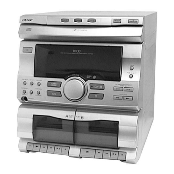
HCD-GRX2/RX33
Photo : HCD-GRX2
CD
SECTION
TAPE
DECK
SECTION
SPECIFICATIONS
Model Name Using Similar Mechanism
CD Mechanism Type
Base Unit Type
Optical Pick-up Type
Model Name Using Similar Mechanism
DECK-A
Tape Transport
Mechanism Type
DECK-B
Outputs
PHONES (stereo phone jack) :
accepts headphones of 8 Ω or more
accepts impedance of 6 to 16 Ω
SPEAKER :
CD player section
System
Compact disc and digital audio system
Laser
Semiconductor laser (λ = 780 nm)
Emission duration: continuous
Laser output
Max. 44.6 µW*
*This output is the value measured at a
distance of 200 mm from the objective
lens surface on the Optical Pick-up Block
with 7 mm aperture.
Frequency response
20 Hz – 20 kHz (± 0.5 dB)
Wavelength
780 – 790 nm
Tape deck section
Recording system
4 -track 2 -channel stereo
Frequency response
60 – 13,000 Hz (± 3dB), using Sony
TYPE Ι cassette
MINI Hi-Fi COMPONENT SYSTEM
US Model
Canadian Model
HCD-RX33
E Model
Australian Model
HCD-GRX2
HCD-G101
CX3
KSM-213BCM
KSS-213B/S-N
HCD-G101
TK20FX-SW943-800
TK20FX-SW943-800
— Continued on next page —
Advertisement
Table of Contents

Related Manuals for Sony HCD-GRX2


Summary of Contents for Sony HCD-GRX2
- Page 1 4 -track 2 -channel stereo DIN power output (Rated) 30 W + 30 W (6 Ω at 1 kHz, DIN) Frequency response 60 – 13,000 Hz (± 3dB), using Sony TYPE Ι cassette Continuous RMS power output (Reference) 35 W + 35W (6 Ω at 1 kHz, 10% THD) Peak music power output (Reference) —...
- Page 2 CRITIQUES POUR LA SÉCURITÉ DE FONCTIONNEMENT. NE COMPONENTS WITH SONY PARTS WHOSE PART NUMBERS REMPLACER CES COMPOSANTS QUE PAR DES PIÈSES SONY APPEAR AS SHOWN IN THIS MANUAL OR IN SUPPLEMENTS DONT LES NUMÉROS SONT DONNÉS DANS CE MANUEL OU PUBLISHED BY SONY.
-
Page 3: Table Of Contents
TABLE OF CONTENTS SAFETY CHECK-OUT 1. GENERAL ................4 After correcting the original service problem, perform the following safety checks before releasing the set to the customer: 2. DISASSEMBLY Check the antenna terminals, metal trim, “metallized” knobs, screws, 2-1. CD Door ................5 and all other exposed metal parts for AC leakage. -
Page 4: General
SECTION 1 GENERAL LOCATION OF PARTS AND CONTROLS !• !¶ !º !¡ !™ !£ !¢ !§ !∞ !ª @º @¡ @™ @£ @¢ @∞ @§ @¶ @• !¶ Disc tray FILE SELECT !• DISC 1 button I/u (POWER) button !ª DISC 2 button TUNER MEMORY REPEAT button @º... -
Page 5: Disassembly
SECTION 2 DISASSEMBLY Note : Follow the disassembly procedure in the numerical order given. 2-1. CD DOOR 2 CD door Two craws 1 Pull out the CD tray and remove the CD door with releasing claws into the direction of arrow. 2-2. -
Page 6: Front Panel
2-3. FRONT PANEL 3 Screw (+BVTP 3 × 10) 4 Screw (+BVTP 3 × 10) 5 Two screw (+BVTP 3 × 10) 6 Two screws (+BVTP 3 × 10) 7 Screw (+PTPWH 3 × 10) 1 Connector (CN401) 9 Front panel 7 Screw (+PTPWH 3 ×... -
Page 7: Cd Tray
2-5. CD TRAY 1 Screw (+P 2.6 × 4) 2 Bracket 5 Flat type wire (CN06) 3 Screw (+P 2.6 × 4) 4 Bracket 6 CD tray 2-6. CD DECODER BOARD 1 Two screws (+BVTP 3 × 10) 6 Flat type wire (CN06) 5 Flat type wire (CN01) 7 CD DECODER board 8 Two screw... -
Page 8: Base Unit
2-7. BASE UNIT 4 Screw (+PTPWH 2.6 × 8) 2 Screw (+PTPWH 2.6 × 8) 3 UD-gear 5 UD-Cam 7 Spring 6 Spring 8 Spring 1 Two screws (+KTP 3 × 8) 9 Base unit 2-8. CASSETTE LID (L) / (R) 1 Cassette lid (L) Four craws 2 Cassette lid (R) -
Page 9: Mechanical Adjustments
SECTION 3 SECTION 4 MECHANICAL ADJUSTMENTS ELECTRICAL ADJUSTMENTS DECK SECTION 0 dB=0.775V Precaution 1. Clean the following parts with a denatured alcohol-moistened Demagnetize the record/playback head with a head swab: damagnetizer. record/playback head pinch rollers Do not use a magnetized screwdriver for the adjustments. erase head rubber belts After the adjustments, apply suitable locking compound to the... - Page 10 Turn the adjustment screw and check output peaks. If the peaks After the adjustments, apply suitable locking compound to the do not match for L-CH and R-CH, turn the adjustment screw parts adjusted. so that outputs match within 2 dB of peak. Adjustment Location: Remove the cassette lid before adjustment (See page 8) L-CH...
- Page 11 TUNER SECTION 0 dB=1µV AM Tuning Voltage Adjustment Main board DC voltmeter – Procedure: Set the reception frequency of the unit to 530 kHz. Adjust L105 for 1.2 ± 0.05 V reading on the DC voltmeter. Set the reception frequency of the unit to 1,710 kHz. Confirm that the voltage reading on the DC voltmeter is within 8.0 ±...
- Page 12 FM Tracking Adjustment FM Tuned Level Adjustment Procedure: FM RF SSG 75 Ω coaxial FM RF SSG oscilloscope Carrier frequency : 98 MHz FM ANTENNA terminal Modulation : AUDIO 1 kHz, 75 kHz SPEAKER terminal (JK501) (JK101) deviation (100%) FM ANTENNA terminal (JK101) : 28 dB (at 75 Ω...
- Page 13 RF Level Check CD SECTION oscilloscope CD DECODER board Note: CD Block is basically constructed to operate without TP (RF) adjustment. Therefore, check each item in order given. CN12 (VC) Use YEDS-18 disc (3-702-101-01) unless otherwise indicated. Use an oscilloscope with more than 10MΩ impedance. Clean the object lens by an applicator with neutral detergent Procedure : when the signal level is low than specified value with the...
-
Page 14: Diagrams
SECTION 5 DIAGRAMS 5-1. CIRCUIT BOARDS LOCATION SW (B) board SW (D) board MOTOR (6P) (S) board SW (C) board MOTOR board DISK board CD DECODER board SW (A) board PANEL board SENSOR board MAIN board H.P board AC POWER board R/P SWITCH board VR board —... -
Page 15: Deck Section
HCD-GRX2/RX33 5-2. BLOCK DIAGRAMS — DECK SECTION — REC/PB EQ AMP IC201 SELECTOR IC301 POWER AMP IC501 PB OUT LINE AMP TAPE B IC302 Q216 Q209 HP901 R CH MUTE MUTE JK303 HEAD SWITCH Q307 Q303 PHONES Q213 BASS BOOST... -
Page 16: Tuner/Cd Section
HCD-GRX2/RX33 — TUNER/CD SECTION — FM/AM MPX FM FRONT END IC102 L101 IC101 FM ANT T101 Q101 CF101 CF102 10.7MHz 10.7MHz FM IF AM/FM TU L RF IF MUTE DECODER 75Ω IF BUFF R CH L102 JK101 FM RF ANTENNA... - Page 17 HCD-GRX2/RX33 5-3. IC BLOCK DIAGRAMS IC01 (CD DECORD BOARD) CXA1782BQ IC102 (MAIN BOARD) LA1831 IC301 (MAIN BOARD) LC75392 IC602 (PANEL BOARD) BU2092 LVROUT RVROUT OSC/FMSD AM RF SMET AM HPF AF DET MPX VCO MPX IN R OUT L OUT...
-
Page 18: Ic Pin Function
Synchro record input. Record:L, Other: H 1-670-391-11 AC POWER BOARD ! PT302 1-431-939-11 TRANSFORMER, POWER (US, CND) 4-962-708-01 EMBLEM (4-A), SONY 4-210-329-01 FILM, BUTTON LENS CD encoder A input. ON: L, OFF: H (Ground) FLD grid signal output 2. ON: H, OFF: L... -
Page 19: Cassette Mechanism Deck Section
6-4. CASSETTE MECHANISM DECK SECTION not supplied not supplied M901 SW202 not supplied HE901 SW203 HRP901 supplied SW204 not supplied not supplied HP901 not supplied not supplied not supplied Ref. No. Part No. Description Remarks Ref. No. Part No. Description Remarks 9-980-286-01 CAP SCREW 2 ×... -
Page 20: Cd Mechanism Deck Section 1
6-5. CD MECHANISM DECK SECTION 1 M103 Ref. No. Part No. Description Remarks Ref. No. Part No. Description Remarks * 201 1-670-801-11 MOTOR BOARD 4-992-183-01 SCREW, RELAY GEAR (B) 3-669-480-11 + PTPWH 2 4-992-174-01 GEAR, CHANGE 4-992-168-01 TRAY, CHANGER BASE 4-992-184-01 WASHER, CHANGE GEAR 4-992-180-01 PLATE, BLIND 4-992-176-01 SPRING, CHANGE GEAR... -
Page 21: Cd Mechanism Deck Section 2
6-6. CD MECHANISM DECK SECTION 2 not supplied M104 Base unit block Ref. No. Part No. Description Remarks Ref. No. Part No. Description Remarks 1-769-856-11 WIRE (FLAT TYPE) (5 CORE) 4-992-192-01 SPRING, BRAKE CAM 4-992-190-01 UD-CAM 4-992-193-01 LEVER, SW 4-992-191-01 UD-GEAR * 263 1-670-800-11 SW (D) BOARD 4-992-195-01 MAGNET... -
Page 22: Base Unit Section (Ksm-213Bcm)
6-7. BASE UNIT SECTION (KSM-213BCM) not supplied M102 M101 Ref. No. Part No. Description Remarks Ref. No. Part No. Description Remarks 4-992-164-01 BASE, KSM MECHANICAL 2-627-003-02 GEAR (B) 4-992-165-01 DAMPER (GREEN) ! 308 8-848-379-31 OPTICAL PICK-UP KSS-213B/S-N 4-992-166-01 DAMPER (RED) * 309 1-639-678-12 MOTOR (6P)(S) BOARD 4-992-167-01 SPRING, MECHANICAL BASE... -
Page 23: Electrical Parts List
SECTION 7 AC POWER ELECTRICAL PARTS LIST CD DECODER NOTE: • Due to standardization, replacements in the • RESISTORS When indicating parts by reference number, parts list may be different from the parts All resistors are in ohms. please include the board name. specified in the diagrams or the components METAL: metal-film resistor The components identified by mark ! or... - Page 24 CD DECODER Ref. No. Part No. Description Remarks Ref. No. Part No. Description Remarks < DIODE > 1-247-903-00 CARBON 1/4W 1-247-855-11 CARBON 1/4W 8-719-911-19 DIODE 1SS119-25 1-247-879-11 CARBON 100K 1/4W 8-719-921-41 DIODE 1SS133T 1-247-847-11 CARBON 4.7K 1/4W D04A 8-719-991-33 DIODE 1SS176 1-247-847-11 CARBON 4.7K 1/4W...
- Page 25 DISK MAIN Ref. No. Part No. Description Remarks Ref. No. Part No. Description Remarks 1-670-387-11 DISK BOARD C132 1-161-047-00 CERAMIC 0.0047uF 10% C133 1-161-047-00 CERAMIC 0.0047uF 10% ********** C134 1-162-294-31 CERAMIC 0.001uF < RESISTOR > C135 1-126-962-11 ELECT 3.3uF C137 1-126-959-11 ELECT 0.47uF R630...
- Page 26 MAIN Ref. No. Part No. Description Remarks Ref. No. Part No. Description Remarks C224 1-162-294-31 CERAMIC 0.001uF C357 1-162-282-31 CERAMIC 100PF C225 1-126-962-11 ELECT 3.3uF C358 1-162-282-31 CERAMIC 100PF C226 1-126-962-11 ELECT 3.3uF C359 1-164-159-11 CERAMIC 0.1uF C228 1-126-964-11 ELECT 10uF C360 1-164-159-11 CERAMIC...
- Page 27 MAIN Ref. No. Part No. Description Remarks Ref. No. Part No. Description Remarks C505 1-126-964-11 ELECT 10uF D208 8-719-991-33 DIODE 1SS133T-77 C506 1-126-964-11 ELECT 10uF D209 8-719-991-33 DIODE 1SS133T-77 C507 1-126-968-11 ELECT 100uF D210 8-719-991-33 DIODE 1SS133T-77 C508 1-126-964-11 ELECT 10uF D211 8-719-991-33 DIODE 1SS133T-77...
- Page 28 MAIN Ref. No. Part No. Description Remarks Ref. No. Part No. Description Remarks < TRANSISTOR > R106 1-247-807-11 CARBON 1/4W R107 1-247-879-11 CARBON 100K 1/4W Q101 8-729-672-42 TRANSISTOR 2SC2724-C R108 1-247-871-11 CARBON 1/4W Q102 8-729-178-63 TRANSISTOR 2SC2786-K R109 1-247-879-11 CARBON 100K 1/4W Q103...
- Page 29 MAIN Ref. No. Part No. Description Remarks Ref. No. Part No. Description Remarks R217 1-247-871-11 CARBON 1/4W R318 1-247-887-00 CARBON 220K 1/4W R218 1-249-409-11 CARBON 1/4W F R319 1-247-855-11 CARBON 1/4W R219 1-247-841-11 CARBON 2.7K 1/4W R320 1-247-855-11 CARBON 1/4W R220 1-249-434-11 CARBON 1/4W...
- Page 30 MAIN MOTOR MOTOR (6P) (S) PANEL Ref. No. Part No. Description Remarks Ref. No. Part No. Description Remarks R408 1-247-855-11 CARBON 1/4W < TRIMMER > R409 1-249-417-11 CARBON 1/4W F R410 1-247-847-11 CARBON 4.7K 1/4W TC101 1-141-304-21 CAP, TRIMMER 10PF R411 1-247-807-11 CARBON 1/4W...
- Page 31 PANEL Ref. No. Part No. Description Remarks Ref. No. Part No. Description Remarks C616 1-130-491-00 MYLAR 0.047uF R606 1-249-417-11 CARBON 1/4W F C617 1-130-491-00 MYLAR 0.047uF R607 1-249-431-11 CARBON 1/4W C619 1-130-491-00 MYLAR 0.047uF R608 1-247-871-11 CARBON 1/4W C620 1-126-933-11 ELECT 100uF R609 1-247-855-11 CARBON...
- Page 32 PANEL R/P SWITCH SENSOR SW (A) SW (B) SW (C) SW (D) Ref. No. Part No. Description Remarks Ref. No. Part No. Description Remarks S616 1-572-674-11 SWITCH, PUSH (FILE SELECT) 1-670-389-11 VR BOARD S617 1-572-674-11 SWITCH, PUSH (DBFB) ********* S618 1-572-674-11 SWITCH, PUSH (DISPLAY) <...
- Page 33 Ref. No. Part No. Description Remarks Ref. No. Part No. Description Remarks (SWEDISH/DANISH/FINNISH) 3-862-423-81 MANUAL, INSTRUCTION (POLISH/RUSSIAN) 4-982-031-01 COVER, BATTERY (for RM-SG5) ************************************************************ ************** HARDWARE LIST ************** 7-685-647-79 SCREW +BVTP 3 × 10 TYPE2 IT-3 7-682-547-04 SCREW +BVTT 3 × 6 (S) 7-682-548-04 SCREW +B 3 ×...
- Page 34 HCD-GRX2/RX33 98C167032-1 Printed in Singapore ©1998.3 Sony Corporation Published by General Engineering Dept. Home A&V Products Company 9-922-792-11 (Shibaura) — 72 —...
- Page 35 HCD-GRX2/RX33 • PARTS LIST Page INCORRECT CORRECT Ref. No. Part No. Description Remarks Part No. Description Remarks US Model 1-126-963-11 ELECT 4.7uF ––––––––––– –––––––––––––––––––––– C04B ––––––––––– –––––––––––––––––––––– 1-126-925-11 ELECT 470uF Canadian Model C07A 1-162-199-31 CERAMIC 10PF 1-162-201-31 CERAMIC 12PF 1-161-494-00 CERAMIC 0.022uF...
- Page 36 : Indicates corrected portion (ADDED) (DELETED) (DELETED) (ADDED) (DELETED) (DELETED) (ADDED) — 3 — — 4 —...