Table of Contents
Advertisement
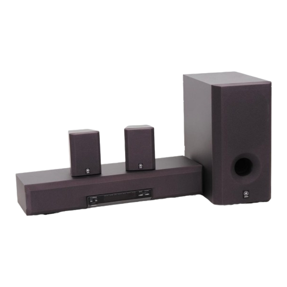
AV-S70/NX-SW70
FRONT SPEAKER (AV-S70)
This manual has been provided for the use of authorized YAMAHA Retailers and their service personnel.
It has been assumed that basic service procedures inherent to the industry, and more specifically YAMAHA Products, are already known and understood by the users,
and have therefore not been restated.
WARNING:
Failure to follow appropriate service and safety procedures when servicing this product may result in personal injury, destruction of expensive
components, and failure of the product to perform as specified. For these reasons, we advise all YAMAHA product owners that any service
required should be performed by an authorized YAMAHA Retailer or the appointed service representative.
IMPORTANT:
The presentation or sale of this manual to any individual or firm does not constitute authorization, certification or recognition of any applicable
technical capabilities, or establish a principle-agent relationship of any form.
The data provided is believed to be accurate and applicable to the unit(s) indicated on the cover. The research, engineering, and service departments of YAMAHA are
continually striving to improve YAMAHA products. Modifications are, therefore, inevitable and specifications are subject to change without notice or obligation to
retrofit. Should any discrepancy appear to exist, please contact the distributor's Service Division.
WARNING:
Static discharges can destroy expensive components. Discharge any static electricity your body may have accumulated by grounding yourself to the
ground buss in the unit (heavy gauge black wires connect to this buss).
IMPORTANT:
Turn the unit OFF during disassembly and part replacement. Recheck all work before you apply power to the unit.
CONTENTS
TO SERVICE PERSONNEL ......................................... 1
FRONT/REAR PANELS .......................................... 1-2
SPECIFICATIONS ......................................................... 3
DISASSEMBLY PROCEDURES .................................. 4
TEST PROGRAM MODE ........................................ 5-6
DSP DIAG MODE ................................................. 7-13
AV-S70 IC DATA ................................................ 14-20
AV-S70 BLOCK DIAGRAM ................................ 21-22
1 0 0 6 9 7
HOME THEATER SYSTEM
SERVICE MANUAL
NX-SW70 is composed of SW-AVS70 and NX-AVS70s.
REAR SPEAKER
(NX-AVS70)
IMPORTANT NOTICE
SW-AVS70 BLOCK DIAGRAM .................................. 23
AV-S70 PRINTED CIRCUIT BOARD ................. 24-33
SW-AVS70 PRINTED CIRCUIT BOARD ........... 34-35
AV-S70 SCHEMATIC DIAGRAM ....................... 36-39
SW-AVS70 SCHEMATIC DIAGRAM .......................... 40
PARTS LIST ........................................................ 41-54
REMOTE CONTROL TRANSMITTER ........................ 55
SUBWOOFER
(SW-AVS70)
REAR SPEAKER
(NX-AVS70)
Advertisement
Table of Contents

Related Manuals for Yamaha AV-S70


Summary of Contents for Yamaha AV-S70
-
Page 1: Table Of Contents
The data provided is believed to be accurate and applicable to the unit(s) indicated on the cover. The research, engineering, and service departments of YAMAHA are continually striving to improve YAMAHA products. Modifications are, therefore, inevitable and specifications are subject to change without notice or obligation to retrofit. -
Page 2: To Service Personnel
AV-S70/NX-SW70 TO SERVICE PERSONNEL AC LEAKAGE EQUIPMENT WALL TESTER OR Critical Components Information. OUTLET UNDER TEST EQUIVALENT Components having special characteristics are marked Z and must be replaced with parts having specifications equal to those originally installed. INSULATING TABLE FRONT/REAR PANELS AV-S70 600 (23–5/8") - Page 3 AV-S70/NX-SW70 SW-AVS70 399 (15–11/16") 200.6 (7–7/8") 335 (13–3/16") 24(15/16") (1–3/4") NX-AVS70 111.5 (4–3/8") 100 (3–15/16") 20 (13/16") 1.4 (1/16")
-
Page 4: Specifications
AV-S70/NX-SW70 SPECIFICATIONS AV-S70 NX-SW70 AMPLIFIER SECTION AMPLIFIER SECTION Minimum RMS Output Power per Channel Minimum RMS Output Power per Channel Front (1kHz, 10% THD, 6Ω) ......30W + 30W Rear (1kHz, 10% THD, 6Ω) ......30W + 30W Signal to Noise Ratio (IHF-A-Network) Sub Woofer (100Hz, 10% THD, 4Ω) ...... -
Page 5: Disassembly Procedures
AV-S70/NX-SW70 AV-S70 DISASSEMBLY PROCEDURES (Remove parts in the order as numbered.) 1. Removal of Grille Assembly. 2. Removal of Amplifier Unit a. Push up the Grille Assembly with a flat tip screwdriver a. Remove 4 wing screws (q) and then remove the Plate or the like inserted from the bottom. -
Page 6: Test Program Mode
AV-S70/NX-SW70 TEST PROGRAM MODE (AV-S70) 1. Procedure for starting Test Program With the power turned off, press the POWER key while pressing the VOLUME key and the DSP key simultaneously. This initiates the Test Program function. When the Test Program is initiated, “01 DEST-Ex” appears on the FL display. - Page 7 AV-S70/NX-SW70 Display Function The DSP DIAG (self-diagnosis) mode is initiated. (Refer to page 7 for the details.) 04 DSP Diag 05 Ver-A1.08 Microprocessor version / date display 05 Ver-A1.08 Example of microprocessor display 05 '99.10.15 Example of microprocessor date display What is displayed varies depending on the microprocessor software.
-
Page 8: Dsp Diag Mode
AV-S70/NX-SW70 DSP DIAG MODE (Self-diagnosis) Use the remote controller supplied as an accessory to select the menu. 1. Procedure for starting DSP DIAG Referring to TEST PROGRAM MODE in the previous section, select/execute “04 DSP Diag”. When “04 DSP Diag” is executed, the current input name appears on the display followed by “Video” > “Sel.1to9 Key”. - Page 9 AV-S70/NX-SW70 Details of DIAG menu 1. Analog Thr. The input is fixed to use the analog (A/D) and has 2 sub-menu items. MAIN BYPSS The main L/R signal is output through the analog bypass without passing the DSP section. The main L/R signal passing through the DSP is output through C/LFE and RL/RR.
- Page 10 AV-S70/NX-SW70 2. DSP Through In the DIGITAL input mode, AC3/PCM AUDIO signal is automatically identified. There are 3 sub-menu items. YSS908-SRAM The main L/R signal is sent through AC3D2av into DSP. After passing through SRAM, the main L/R signal is output through L+R and C/LFE and RL/RR signals through (L+R)/2.
- Page 11 AV-S70/NX-SW70 DSP FULL BIT The main L/R is input through AC3D2av to DSP and then output through all channels. The head margin is eliminated and the digital data is output in digital full bit. The same applies as “YSS908” except that the digital data is output in full bit at D/A.
- Page 12 AV-S70/NX-SW70 4. Pro Logic The sub-menu items include selection of Pro-logic (The auto input balance is off.) and EFFECT OFF. CENTER LARGE When the analog, PCM audio or AC-3 2/0 mode is used, L, R, C, S signals are pro- logic decoded and output.
- Page 13 AV-S70/NX-SW70 5. Speakers Set (for reference only) This menu is for checking during the production process and not for servicing. The input L/R signal is output through the specified channels according to the sub-menu. There are 7 sub-menu items. The signal output from the DSP section is normally in the EFFECT OFF state in the menus from 1 to 3.
- Page 14 AV-S70/NX-SW70 6. Effect Off All effect functions are turned off. 7. Manual Test The test noise is output by the noise generator with a built-in DSP through the channels specified by the sub-menu. Noise is output through all channels. MAIN L Noise is output through the MAIN L channel.
-
Page 15: Av-S70 Ic Data
AV-S70/NX-SW70 AV-S70 IC DATA µ IC701 : M30218FCFP (16 bit -COM) P67/FLD7 P24/FLD36 P66/FLD6 P25/FLD37 P65/FLD5 P26/FLD38 P64/FLD4 P27/FLD39 P63/FLD3 P30/FLD40 P62/FLD2 P31/FLD41 P61/FLD1 P32/FLD42 P60/FLD0 P33/FLD43 P34/FLD44 P107/AN7 P35/FLD45 P106/AN6 P36/FLD46 P105/AN5 P37/FLD47 P104/AN4 P40/FLD48 P103/AN3 P41/FLD49 P102/AN2 P42/FLD50... - Page 16 AV-S70/NX-SW70 µ IC701 : M30218FCFP (16 bit -COM) PORT Name IN/OUT Function CMOS (DSP) /IC AC3D OUT (/ICAC) CLK1 S-CLK (DSP) AC3D CLK OUT(CLKAC) (Serial I/O-1) RxD1 S-IN (DSP) AC3D DATA IN(RXAC) (Serial I/O-1) TxD1 S-OUT (DSP) AC3D DATA OUT(TXAC)
- Page 17 • When the protection circuit of the subwoofer is at work, approximately 0 to 2V voltage is obtained and the protection circuit of AV-S70 works together with it. 2. When the system connector is not connected or the power of the subwoofer (NX-SW70) is not turned ON, only VIRTUAL...
- Page 18 AV-S70/NX-SW70 IC3 : YM3436D DIR ( Digital Format Interface Receiver ) 24 26 28 25 17 15 14 13 12 31 DAUX HDLT EXTW SYSTEM DOUT CLOCK TSTN TIMING SYNC GENERATOR SYNC CTLP D DIN DATA CLOCK (N.C.) EIAJ (AES/EBU)
-
Page 19: Top View
AV-S70/NX-SW70 IC4 : YSS908-F (P.C.B. DSP) AC3Dav PVSS SDWCK0 SDWCK1 SDBCK0 SDBCK1 SDIA0 SDOB0 SDIA1 SDOB1 RAMA1 SDOB2 RAMA0 RAMA7 RAMWEN RAMA8 RAMOEN RAMA9 TOP VIEW IPORT7 OPORT7 IPORT6 OPORT6 IPORT5 OPORT5 IPORT4 OPORT4 IPORT3 OPORT3 IPORT2 OPORT2 IPORT1 OPORT1... - Page 20 AV-S70/NX-SW70 IC4 : YSS908-F AC3Dav Name Function PVDD +5V power supply RAMCEN External SRAM chip enable terminal RAMA16 External SRAM address terminal 16 RAMA15 External SRAM address terminal 15 SDIB0 PCM input terminal 0 to Sub DSP SDIB1 PCM input terminal 1 to Sub DSP...
- Page 21 AV-S70/NX-SW70 IC4 : YSS908-F AC3Dav Name Function AC-3 CRC error detect terminal MUTE Auto mute detect terminal KARAOKE AC-3 KARAOKE data detect terminal SURENC AC-3 2/0 mode Dolby surround encode input detect terminal /SDBCK0 SDBCK0 invert clock output terminal RAMA6...
-
Page 22: Av-S70 Block Diagram
AV-S70/NX-SW70 AV-S70 BLOCK DIAGRAM (1/2) SIGNAL SENSOR L : 10 mV M–SENSOR M : 5 mV SELECTOR IC H : 3mV CN105 4 IC103 LC78212 IC107 IC102 INPUT 1 (30) (27) (AUX) 6 (2) 7 (1) M5220FP L : IC104... - Page 23 AV-S70/NX-SW70 AV-S70 BLOCK DIAGRAM (2/2)
-
Page 24: Sw-Avs70 Block Diagram
AV-S70/NX-SW70 SW-AVS70 BLOCK DIAGRAM... -
Page 25: Av-S70 Printed Circuit Board
AV-S70/NX-SW70 AV-S70 PRINTED CIRCUIT BOARD DSP-FL ( A ) P. C. B. (Component side) DSP-FL ( A ) P. C. B. (Foil side) DIGITAL DIGITAL FROM : DSP–FL (B) Semiconductor Location Ref. No. Location Ref. No. Location Ref. No. Location Point q (Pin 13 of IC3) V : 2V/div, H : 0.1 µsec/div... - Page 26 AV-S70/NX-SW70 AV-S70 PRINTED CIRCUIT BOARD DSP–FL ( B ) P. C. B. (Component side) FROM : AMP (A) Point w (Pin 13 of IC701) V : 2V/div, H : 0.1 µsec/div DC, 1 : 1 probe FROM : DSP–FL (A)
- Page 27 AV-S70/NX-SW70 AV-S70 PRINTED CIRCUIT BOARD AMP ( B ) P. C. B. AMP ( C ) P. C. B. (Component side) (Component side) AMP ( B ) P. C. B. (Foil side) AMP ( C ) P. C. B. (Foil side)
- Page 28 AV-S70/NX-SW70 AV-S70 PRINTED CIRCUIT BOARD AMP ( A ) P. C. B. (Component side) INPUT AMP ( E ) P. C. B. (Component side) TO : AMP (B) FROM : AMP (C) MUTE –15 SP–RY SW–PRT PRE–OUT TruBass AMP–PRT B–BST...
- Page 29 AV-S70/NX-SW70 AV-S70 PRINTED CIRCUIT BOARD AMP ( D ) P. C. B. (Component side) AMP ( A ) P. C. B. (Foil side) Semiconductor Location Ref. No. Location IC101 IC102 IC104 IC105 IC107 IC120...
-
Page 30: Sw-Avs70 Printed Circuit Board
AV-S70/NX-SW70 SW-AVS70 PRINTED CIRCUIT BOARD AMP ( A ) P. C. B. AMP ( B ) P. C. B. (Component side) (Component side) SYSTEM CONNECTOR REAR SPEAKER AMP ( C ) P. C. B. (Component side) FROM : AMP (B) -
Page 31: Av-S70 Schematic Diagram
AV-S70/NX-SW70 IC101 : TC4052BF AV-S70 SCHEMATIC DIAGRAM (1/4) Analog Multiplexers/Demultiplexers INHIBIT REAR L P-37 LEVEL BINARY TO 1-OF-4 CONVERTER DECODER WITH INHIBIT 22.5 MAIN L –22.4 INPUT SELECTOR DIGITAL VOLUME INHIBIT 0x, 0y 1x, 1y MUSIC SENSOR 2x, 2y 3x, 3y... - Page 32 AV-S70/NX-SW70 IC6 : CS4227-KP AV-S70 SCHEMATIC DIAGRAM (2/4) AD Converter/DA Converter P-38 44 43 42 41 40 39 38 37 36 35 34 DATAUX SDIN2 HOLD SDIN3 SCL/CCLK CLKOUT SDA/CDOUT AD1/CDIN AD0/CS SPI/I2C DIGITAL 2 AOUT6 AIN3R AOUT5 MAIN L...
- Page 33 AV-S70/NX-SW70 AV-S70 SCHEMATIC DIAGRAM (3/4) V701 : 13-BT-169GNK (V4879700) PATTERN AREA PIN CONNECTION Pin No. P-39 Connection F1 NP NP NX P35 P34 P33 P32 P31 P30 P29 P28 P27 P26 P25 P24 P23 P22 P21 P20 P19 P18 P17 P16 P15 P14 P13 P12 P11 17.4...
- Page 34 AV-S70/NX-SW70 AV-S70 SCHEMATIC DIAGRAM (4/4) R533 –3.1 MAIN L –8.8 –8.8 MAIN L 28.7 –14.9 –14.8 –29.0 14.6 14.6 –11.5 P-36 –29.0 –11.5 28.7 P-36 –11.5 26.7 MUTING SYSTEM POWER AMP CONNECTOR –11.5 IC503 : TRUBASS IC501, 502 : LM1875T...
-
Page 35: Sw-Avs70 Schematic Diagram
AV-S70/NX-SW70 SW-AVS70 SCHEMATIC DIAGRAM REAR L 27.5 11.9 –11.7 –0.1 –29.3 –26.3 28.8 –11.5 27.6 11.9 26.1 27.5 –0.1 11.7 26.3 11.7 –0.1 –29.3 11.7 –11.6 –11.6 23.4 –11.5 11.7 –1.5 –11.6 –11.9 REAR L 11.9 29.1 11.2 27.1 11.9 29.2... -
Page 36: Parts List
AV-S70/NX-SW70 WARNING PARTS LIST Components having special characteristics are marked Z and must be replaced with parts having specifications equal to those originally installed. Carbon resistors (1/6W or 1/4W) are not included in the ELECTRICAL PARTS ELECTRICAL PARTS List. For the parts No. of the carbon resistors, refer to last page. - Page 37 AV-S70/NX-SW70 AV-S70 P.C.B. AMP Schm Schm Ref. PART NO. Description Remarks Ref. PART NO. Description Remarks AAX15150 P.C.B. 331416 * C305 AAX11180 C.POL 0.1uF 50V 065007 * C101 AAX10700 C.CE.CHP 220pF 50V 065619 * C306 AAX10300 C.EL 33uF 16V 066389 * C102 AAX10700 C.CE.CHP...
- Page 38 AV-S70/NX-SW70 AV-S70 P.C.B. AMP Schm Schm Ref. PART NO. Description Remarks Ref. PART NO. Description Remarks * C609 AAX10430 C.EL 10uF 25V 066768 * CN405 AAX10550 CN S2P3-VH 081663 * C610 AAX10430 C.EL 10uF 25V 066768 CN501 VC015000 CN EH 6P...
- Page 39 AV-S70/NX-SW70 AV-S70 P.C.B. AMP & DSP-FL Schm Schm Ref. PART NO. Description Remarks Ref. PART NO. Description Remarks IC605 XF291A00 IC uPC4570G2 070173 * R401 AAX11900 R.CAR.FP 2.2Ω 1/4W 055504 * JK101 AAX10960 JACK.PIN HSP-248V1 056838 * R402 AAX11900 R.CAR.FP 2.2Ω...
- Page 40 AV-S70/NX-SW70 AV-S70 P.C.B. DSP-FL Schm Schm Ref. PART NO. Description Remarks Ref. PART NO. Description Remarks * C27 AAX10710 C.CE.CHP 0.022uF 50V 065621 * C81 AAX11240 C.POL 3300pF 50V 065087 * C28 AAX10690 C.CE.CHP 0.1uF 25V 065611 * C81 AAX11240 C.POL...
- Page 41 AV-S70/NX-SW70 AV-S70 P.C.B. DSP-FL Schm Schm Ref. PART NO. Description Remarks Ref. PART NO. Description Remarks * C852 AAX10690 C.CE.CHP 0.1uF 25V 065611 L801 GE901970 COIL CHK LAV35VB 680K 055508 * C853 AAX10690 C.CE.CHP 0.1uF 25V 065611 * PJ801 AAX10970 JACK.PIN...
- Page 42 AV-S70/NX-SW70 CHIP RESISTORS Schm Schm Ref. PART NO. Description Remarks Ref. PART NO. Description Remarks RD256430 R.CAR.CHP 4.3KΩ 1/8W 067775 XX699050 R.CAR.CHP 2.2KΩ 1/8W 067732 RD257300 R.CAR.CHP 30KΩ 1/8W 067753 XX699060 R.CAR.CHP 3.3KΩ 1/8W 067758 AAX11390 R.CAR.CHP 36KΩ 1/8W 055459 XX699070 R.CAR.CHP...
- Page 43 AV-S70/NX-SW70 SW-AVS70 P.C.B. AMP Schm Schm Ref. PART NO. Description Remarks Ref. PART NO. Description Remarks AAX12780 P.C.B. 057955 * C154 AAX11180 C.POL 0.1uF 50V 065007 * C101 AAX10260 C.EL 22uF 16V 066345 * C155 AAX10150 C.EL 10uF 16V 066282 * C102 AAX10260 C.EL...
- Page 44 AV-S70/NX-SW70 SW-AVS70 P.C.B. AMP Schm Schm Ref. PART NO. Description Remarks Ref. PART NO. Description Remarks * L101 AAX12190 COIL.CHOKE 1.5uH 074417 TM102 XX707320 PIN IPS-5007 064821 * L102 AAX12190 COIL.CHOKE 1.5uH 074417 VP206500 HOLDER.FUS EYF-52BCT 074277 * L103 AAX12190 COIL.CHOKE 1.5uH 074417 AAX10900 HEAT.SINK...
- Page 45 AV-S70/NX-SW70 AV-S70 EXPLODED VIEW...
- Page 46 AV-S70/NX-SW70 AV-S70 MECHANICAL PARTS Ref. PART NO. Description Remarks Markets * 1- 1 AAX10600 SIDE PANEL 054960 * 1- 1 AAX10610 SIDE PANEL 054962 * 1- 2 AAX11040 GRILLE ASS’Y 055653 * 1- 3 AAX11330 ENCLOSURE 055073 1- 4 XY128A00 SPEAKER...
- Page 47 AV-S70/NX-SW70 Ref. PART NO. Description Remarks Markets ACCESSORIES * 200 V5633900 REMOTE CONTROL 059946 * 200-1 AAX15160 LID 331540 AAX11350 FASTENER TAPE 2pcs 055593 AAX10940 PIN CORD 2p 3mx1 055701 BATTERY SUM4,AAA,R03 New Parts...
- Page 48 AV-S70/NX-SW70 SW-AVS70 EXPLODED VIEW 2-10 2-10 2-15 2-15 2-17 2-18 2-16 2-10 3(B) 2-7-1 2-7-3 2-7-2 2-12 2-7-7 2-13 2-7-4 2-11 2-7-5 2-7-6 2-18 2-17 3(A) 2-14 3(C)
- Page 49 AV-S70/NX-SW70 SW-AVS70 MECHANICAL PARTS Ref. PART NO. Description Remarks Markets * 1- 1 AAX12510 SPEAKER 16cm 055732 * 1- 2 AAX12310 GRILLE ASS’Y 055754 * 1- 3 AAX12040 ENCLOSURE 055038 * 1- 4 AAX12290 FOOT 055357 1- 5 XX701830 NUT...
-
Page 50: Remote Control Transmitter
1MΩ VBAT VBAT 820Ω P51/T02 100kΩ 6.8Ω 22Ω 2N3904 P50/T10/T00 8550D P22/RXD/S10 VBAT P31/INTP1 1.5V x 2 P32/INTP2/CPT2 Initial code of YAMAHA CUSTOM DATA FUNCTION (HEX) (HEX) DSP SET INPUT TruBass VOL – — — — — VOL + TEST DSP ON/OFF —... - Page 51 AV-S70/NX-SW70 Parts List for Carbon Resistors Value 1/4W Type Part No. 1/6W Type Part No. Value 1/4W Type Part No. 1/6W Type Part No. 1.0 Ω 3100 3100 7100 10 kΩ 7100 HJ35 HF85 HF45 HF45 1.8 Ω 3180 7110 11 kΩ...