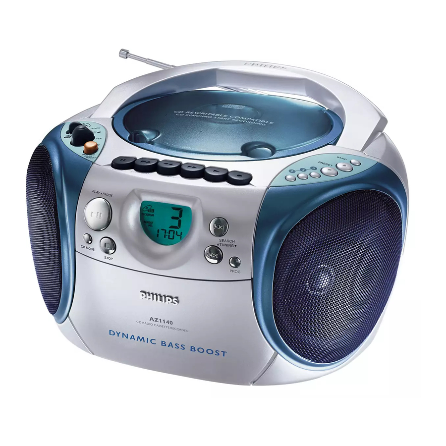
Philips AZ1140 Service Manual
Cd stereo radio recorder
Hide thumbs
Also See for AZ1140:
- User manual (44 pages) ,
- Instrukcja obs?ugi (12 pages) ,
- Specifications (2 pages)
Table of Contents
Advertisement
Quick Links
See also:
User Manual
CD Stereo Radio Recorder
TABLE OF CONTENTS
Handling chip components and safety
Technical Specification & Service Tools
..................................................
Service Measurement
................................................
Connections & Controls
.................................................
Instructions for use
...................................................
Disassembly Diagram
........................................
CD Service Test Program
.............................................................
Block Diagram
...........................................................
Wiring Diagram
CONTROL BOARD
...................................................
.......................................................
layout diagram
SWITCH & VOLUME BOARD
.......................................................
layout diagram
TUNER BOARD
.......................................................
circuit diagram
.......................................................
layout diagram
Safety regulations require that the set be restored to its original
condition and that parts which are identical with those specified
be used.
C
Copyright 1995 Philips Consumer Electroncis B.V. Eindhoven, The Netherlands
All rights reserved. No part of this publication may be reproduced, stored in a retrieval
system or transmitted, in any form or by any means, electronic, mechanical, photocopying,
or otherwise without the prior permission of Philips.
Published by SS 0024 Service Audio
PCS 104 409
chapter
.............................
1 - 1
..........................
2 - 1
2 - 2
3 - 1
3 - 2 to 3 - 6
4 - 1
4 - 2 to 4 - 3
5 - 1
6 - 1
7 - 1, 7 - 3
7 - 2
8 - 1
9 - 1
9 - 2
Printed in The Netherlands
MAIN BOARD
.......................................................
circuit diagram
.......................................................
layout diagram
RECORDER & BEAT CUT BOARD
.......................................................
circuit diagram
.......................................................
layout diagram
CD MODULE
.......................................................
circuit diagram
.......................................................
layout diagram
EXPLODED VIEWS DIAGRAM
.................................................................
cabinet
............................................................
tape deck
.....................................................
Mechanical partslist
...............................................
Electrical partslist
Copyright reserved
Subject to modification
AZ1140
AZ1141
AZ1142
AZ1143
AZ1145
all versions
chapter
10 - 1
10 - 2
11 - 1
11 - 2
12 - 2
12 - 1
13 - 1
13 - 2
13 - 2
14 - 1 to 14 - 4
CLASS 1
LASER PRODUCT
3140 785 22260
GB
Advertisement
Table of Contents

Summary of Contents for Philips AZ1140
- Page 1 LASER PRODUCT Copyright 1995 Philips Consumer Electroncis B.V. Eindhoven, The Netherlands All rights reserved. No part of this publication may be reproduced, stored in a retrieval system or transmitted, in any form or by any means, electronic, mechanical, photocopying, or otherwise without the prior permission of Philips.
-
Page 2: Technical Specifications
TECHNICAL SPECIFICATIONS GENERAL TUNER - AM SECTION Tuning range MW : 531 - 1602 kHz Mains voltage -/00 : 230 V -/17 : 520 - 1730 kHz -/01/11/16 : 120/230 V LW : 153 - 279 kHz -/05/10 : 240 V IF frequency : 450 kHz ±... - Page 3 CONNECTIONS AND CONTROLS PCS 104 411...
- Page 4 INSTRUCTIONS FOR USE PCS 104 412...
- Page 5 INSTRUCTIONS FOR USE PCS 104 413...
- Page 6 INSTRUCTIONS FOR USE PCS 104 414...
- Page 7 INSTRUCTIONS FOR USE PCS 104 415...
- Page 8 INSTRUCTIONS FOR USE PCS 104 416...
- Page 9 14-4 ELECTRICAL PARTSLIST - CD99 DA11 - RESISTORS - 4888 482205120008 Jumper 4889 482205120008 Jumper - COILS & FILTERS - 1810 482224273557 Filter CST8,46MTW-TF01 5803 482215711231 Coil LAN02TB1R0J - DIODES - 6877 482213011564 Diode UDZ3.9B - IC & TRANSISTORS - 7800 482220917324 IC SAA7325H...
- Page 10 12-2 12-2 12-2 CD99 DA11 - CIRCUIT DIAGRAM 1800 D1 2806 E4 2813 E9 2820 B10 2827 C14 2834 F5 2841 C1 2865 D5 2875 D5 3801 A1 3808 A2 3815 E5 3822 E7 3829 A11 3838 D14 3845 G12 3852 F5 3859 H5 3890 B4...
- Page 11 13-1 13-1 13-1 EXPLODED VIEW DIAGRAM - CABINET SCREW LIST 1. C2 x 10 2. C2 x 12 3. C2.5 x 9.5 4. C3 x 7.5 5 (2x) 5. C3 x 8 6. C3 x 9 7. C3 x 10 8.

