Table of Contents
Advertisement
Quick Links
PREFACE
Thank for purchasing small general-purpose
multi-functional inverter MOSCON-E7.
MOSCON-E7 is a small and easy to use inverter.
This
user's
manual
maintenance and inspection, troubleshooting and
specifications of the MOSCON-E7.
Read this user's manual thoroughly for safe
operation of the system and retain for future
reference.
Samsung Electronics Co., Ltd.
Copyright¨ Ï 2 001 Samsung Electronics Co., Ltd.
MOSCON-E7 is trademarks of Samsung Electronics Co., Ltd.
The software and hardware described in this manual is protected
No part of this manual may be photocopied or reproduced in part
consent of Samsung Electronics Co., Ltd.
We will try our best to meet your demands with this manual.
Contact our office stated below in case of being a printing erro
this manual.
Contact Office :
Samsung Electronics Co., Ltd.
41 6 , Maetan-3 Dong, Paldal-Gu, Suwon City, K y ungki-Do, K o rea
TEL : 8 2 -31-200-24 8 9
FAX : 8 2 -31-200-229 5
describes
installation,
by the copyright.
or in whole without the written
r, mistakes and improvement in
General precautions
• This manual may contain some drawings with the
cover or protective shields removed for more
detail and clear explanation of the device. Make
sure to reassemble the device before operation.
• The information in this manual may be subject to
change without a previous notice in case of
modification or improvement, or changes in
specifications. Such modifications are denoted
by a revised manual number.
• Contact your Samsung representative or the
nearest Samsung sales office to order a copy of
this manual if it has been damaged or lost.
• Samsung is not responsible for any modification
of the product made by the user, since that will
void your guarantee.
Advertisement
Table of Contents

Related Manuals for Samsung MOSCON-E7

Summary of Contents for Samsung MOSCON-E7
-
Page 1: General Precautions
Thank for purchasing small general-purpose cover or protective shields removed for more multi-functional inverter MOSCON-E7. detail and clear explanation of the device. Make MOSCON-E7 is a small and easy to use inverter. sure to reassemble the device before operation. This user’s... -
Page 2: Safety Precautions
Safety precautions This user’s manual uses (Danger), (Caution) or (Note) for the MOSCON E-7 User’s Manual safety precautions depending on the degree of precautions. CAUTION DANGER: Wrong handling may cause a dangerous • Do not carry the inverter by holding the plastic parts, but hold the situation, which can lead to death or a heatsink. - Page 3 • Check if the voltage of the inverter rated voltage satisfies with the AC power supply voltage. • Record the previous parameters (even though Moscon-E7 records Otherwise, it may cause fire or injury the information of the last parameter), the records can be useful in case of malfunction or errors.
- Page 4 MOSCON E-7 User’s Manual Safety precautions CAUTION Maintenance and inspection • Do not touch the COMOS IC in the control board directly. DANGER Otherwise it can be damaged by static electricity. • Do not change the wiring, or remove the digital operator or •...
-
Page 5: Table Of Contents
Contents - 1 MOSCON-E7 User’s Manual Contents 3.6.3 Dealing with inductive noises ------------------------------------------------------------------- 3-16 3.6.4 Dealing with radio interference (RFI) -------------------------------------------------------- 3-16 1.Overview 3.6.5 Cable length between inverter and motor ---------------------------------------------------- 3-17 ---------------------------------------------------------------------------------------- 1-1 3.7 Precautions when wiring -------------------------------------------------------------- 3-18 1.1 Main features... - Page 6 Contents - 3 MOSCON-E7 User’s Manual 5.6 C-Parameter : H/W functionality setup 5.4.1 Frequency control functions --------------------------------------------------------------- 5-15 ----------------------------- 5-31 5.4.1.1 Setting the frequency/speed command: F0.01~F0.09 -------------------------------- 5-15 5.6.1 V/f setting ----------------------------------------------------------------------------------------- 5-31 5.4.2 Frequency limit --------------------------------------------------------------------------------- 5-16 5.6.1.1 Setting V/f : C0.01 ---------------------------------------------------------------------------------------- 5-31 5.4.2.1 Setting lower/upper frequency limit : F1.01,F1.02 ------------------------------------- 5-16...
- Page 7 Contents - 5 MOSCON-E7 User’s Manual -------------------------------------MEMO------------------------------------- 5.7.5.7 Setting the fan operating method : H4.07 --------------------------------------------------- 5-59 5.8 P-Parameter : Protective functions -------------------------------------------------- 5-60 5.8.1 Motor overload protection --------------------------------------------------------------- 5-60 5.8.1.1 Select motor protection : P0.01 -------------------------------------------------------------------- 5-60 5.8.1.2 Motor protection time constants : P0.02 ----------------------------------------------------------------- 5-61 5.8.1.3 Motor selection: P0.03 ------------------------------------------------------------------------------------- 5-62...
- Page 8 List of figures - 1 MOSCON-E7 User’s Manual List of figures Figure 5.5 Setting jumping frequencies -------------------------------------------------- 5-18 Figure 5.6 Acceleration/deceleration time switching frequency --------------------- 5-19 1.Overview Figure 5.7 Setting S-curve characteristics ---------------------------------------------- 5-21 Figure 5.8 DC braking timing chart -------------------------------------------------------- 5-22 Figure 1.1 System diagram -------------------------------------------------------------------- 1-5...
- Page 9 MOSCON-E7 User’s Manual List of tables -------------------------------------MEMO------------------------------------- 1.Overview Table 1.1 Dimensions of FARA MOSCON-E7 -------------------------------------------- 1-7 Table 1.2 Specifications for 200V class --------------------------------------------------------- 1-8 Table 1.3 Specifications for 400V class -------------------------------------------------------- 1-10 3. Wiring Table 3.1 200V class main circuit terminal functions ---------------------------------------- 3-7 Table 3.2 400V class main circuit terminal functions ------------------------------------------ 3-7...
-
Page 10: Main Features ------------------------------------------------------------------------------------
1. Overview MOSCON-E7 User’s Manual 1. Overview An overview of the MOSCON-E7 and its functions are described in this chapter. 1.1 Main features ................1-3 1.2 System diagram................. 1-5 1.3 Dimensions................1-6 1.4 Specifications ................1-8... -
Page 11: Overview
Small size & uniform height • Small size & weight allows convenient installation and easy maintenance. • The height of Moscon-E7 is 128mm regardless of its rating. This allows optimal utilization of installation area. High performance • Built-in digital speed controller adopting 32bit RISC micro-processor allows high precision &... -
Page 12: System Diagram
1. Overview MOSCON-E7 User’s Manual 1.2 System diagram 1.3 Dimensions Digital operator Sticker marked capacity Front cover Wiring holes for control circuit Wiring holes for main circuit Cooling fan Heatsink Mounting hole Opening the covers Main circuit terminal block Ground terminal Figure 1.2 Dimensions of 1 phase 20P4 and 3 phase 20P4, 20P7... -
Page 13: Specifications
1. Overview MOSCON-E7 User’s Manual 1.4 Specifications Table 1.2 Specifications for 200V class 20P4 20P7 21P5 22P2 23P7 3 phase 20P4S 20P7S 21P5S 22P2S 1 phase Max. Applicable Motor Capacity[kW] Inverter Capacity[kVA] (1 phase) (1.1) (1.7) (2.7) (3.7) ( - ) Figure 1.4 Dimension of 1 phase 22P2 and 3 phase 23P7, 42P2~43P7... -
Page 14: Table 1.3 Specifications For 400V Class
1. Overview 1-10 MOSCON-E7 User’s Manual Table 1.3 Specifications for 400V class Starting Torque 150%/3Hz Motor stops in 1 minute at approx. 150% of Motor Overload motor rated current. 40P4 40P7 41P5 42P2 43P7 3 phase Instantaneous Motor stops immediately at 200% of inverter Max. - Page 15 1. Overview 1-11 1-12 MOSCON-E7 User’s Manual 1.5 Short circuit rations Motor coasts to stop in 1 minute at approx. Inverter Overload 150% of inverter rated current. Suitable for use in a circuit capable of delivering not more than 5kA rms Overvoltage Motor stops at 820V or higher.
-
Page 16: Installation
2. Installation MOSCON-E7 User’s Manual 2. Installation Nameplate information and installation site are described in this chapter. 2.1 Receiving ................... 2-3 2.2 Nameplate Information ............2-4 2.3 Installation................. 2-5... -
Page 17: Receiving
MOSCON-E7 User’s Manual 2. Installation 2.1 Receiving 2.2 Nameplate information Program version Confirm the following upon delivery of the Moscon-E7: MODEL : SI43P7E7/EXP PRG:V019 Model number Input Voltage : AC3PH 380-460V 50/60Hz 12.0A Input specifications Output Power: AC3PH 0-460V 6.5kVA 8.6A 0.01-600Hz Output specifications •... -
Page 18: Installation
MOSCON-E7 User’s Manual 2. Installation 2.3 Installation 2.3.2 Installation site 2.3.1 Precautions for delivery and installation DANGER • Do not inspect components unless inside “Charge” lamp is off. It may cause an electric shock. Free from oil mist and Free from direct... -
Page 19: Controlling The Ambient Temperature
MOSCON-E7 User’s Manual 2. Installation 2.3.3 Controlling the ambient temperature 2.3.4 Installation space To maintain the optimum condition, the inverter should be installed at Install the inverter on a vertical surface to enhance the cooling effect. the ambient temperature of –10¡ É ~40¡ É . -
Page 20: Wiring
3.Wiring MOSCON-E7 User’s Manual 3. Wiring Wiring specifications, terminals, main circuit terminal connection, peripheral device connection precautions in wiring are described in this chapter. 3.1 Connection diagram ..............3-4 3.2 Terminal block configuration ..........3-6 3.3 Main circuit terminal functions ..........3-7 3.4 Control circuit terminal functions ......... -
Page 21: Connection Diagram
MOSCON-E7 User’s Manual 3.1 Connection diagram DANGER The connection diagram of the Moscon-E7 is shown below. When using the digital operator, the motor can be operated by wiring • Always turn OFF the input power supply before wiring. only the main circuits. -
Page 22: Terminal Block Configuration
3.Wiring MOSCON-E7 User’s Manual 3.2 Terminal block configuration Braking Unit or Auxiliary Capacitor (optional) Ground terminal Braking resistor Main circuit terminal Unit (optional) block External DC reactor to Built-in braking unit is available improve power factor. for the 400V class. Thus, the... -
Page 23: Main Circuit Terminal Functions
3.Wiring MOSCON-E7 User’s Manual 3.3 Main circuit terminal functions 3.4 Control circuit terminal functions Table 3.1 200V class main circuit terminal functions Table 3.3 Control circuit terminal block Purpose Symbol Terminal Function Signal level Default setting Main circuit power input... -
Page 24: Connections To Peripheral Devices
MOSCON-E7 User’s Manual 3-10 3.5 Connections to peripheral devices 3.6 Wiring the main circuits Examples of connections between the Moscon-E7 and peripheral 3.6.1 Wiring on the input side of main circuit devices are shown in the figure below Power supply 3.6.1.1 Installing a molded-case circuit breaker... -
Page 25: Installing An Ac Reactor/Dc Reactor
3.Wiring 3-11 MOSCON-E7 User’s Manual 3-12 Table 3.4 MCCB and magnetic contactor Table 3.5 DC Reactor Rated Magnetic MCCB Inverter capacity(kW) Capacity Model Output Contactor (kVA) Current(A) Rated Current(A) Current[A] 200V Class 20P4 Inductance[mH] 20P7 Current[A] 21P5 400V Class Inductance[mH] 22P2 11.0... -
Page 26: Installing A Noise Filter On Power Supply Side
3.Wiring 3-13 MOSCON-E7 User’s Manual 3-14 Table 3.7 Application of the surge absorber Description Model Specification ◠ Large Capacity Coil ◠ DCR2-50A 22E AC250V 0.5u § Þ 200§ Ù except Relay ◠ ~230V Control Relay DCR2-10A 25C AC250V 0.1 § Þ... -
Page 27: Wiring On The Output Side Of Main Circuit
3.Wiring 3-15 MOSCON-E7 User’s Manual 3-16 3.6.2 Wiring on the output side of main circuit 3.6.3 Dealing with inductive noises • As mentioned previously, noise filter can be used to prevent the 3.6.2.1 Precautions when wiring on the output side of main circuit inductive noise generated on the output side. -
Page 28: Cable Length Between Inverter And Motor
3.Wiring 3-17 MOSCON-E7 User’s Manual 3-18 3.6.5 Cable length between inverter and motor 3.7 Precautions when wiring • If the cable between the inverter and motor is long and the carrier 3.7.1 Control circuit wiring precautions frequency is high, high-frequency current is leaked from the cable and •... -
Page 29: Grounding
• Use the GND cable specified in the technical standards for electrical facilities. Wire the cable as short as possible. • When several MOSCON-E7 are used, ground each unit as shown below. Do not loop the ground as example ¨ Ï . -
Page 30: Cable Specification
3.Wiring 3-21 MOSCON-E7 User’s Manual 3-22 3.9 Cable specification 3.10 Wiring check Determine the cable size for the main circuit. The line voltage drop should be within 2% of the rated voltage. The line voltage drop is calculated as below:... -
Page 31: Digital Operator
4.Digital operator MOSCON-E7 User’s Manual 4 Digital operator All functions of the MOSCON-E7 are controlled by the digital operator. Descriptions of the display and the modes are described in this chapter. 4.1 Usage of digital operator ............4-4 4.2 Monitoring functions of digital operator......4-5... -
Page 32: Usage Of Digital Operator
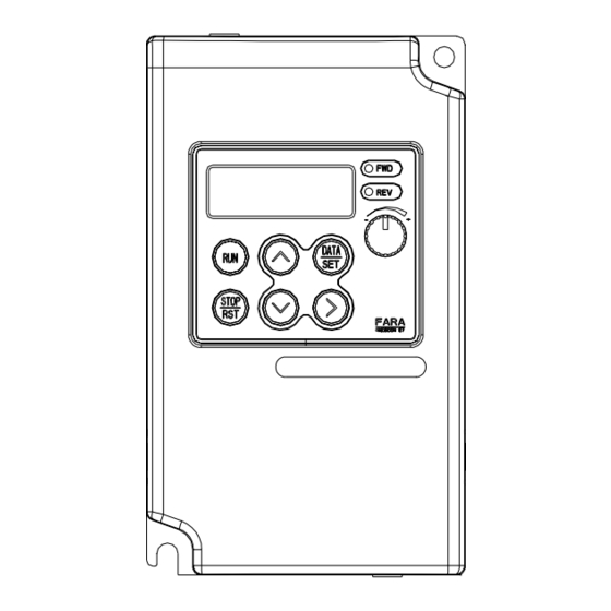
4.Digital operator MOSCON-E7 User’s Manual 4.1 Usage of digital operator FWD LED: • Digital operator can be used for: 7-Segment Display: Lit when the Displays data for monitoring and - basic command (RUN, STOP, Error reset, etc.), motor is running parameters with 4 characters. -
Page 33: Monitoring Functions Of Digital Operator
4.Digital operator MOSCON-E7 User’s Manual 4.2 Monitoring functions of digital operator 4.3 Test run Command Frequency U0.01 Power On U0.02 U0.12 Output Frequency S/W version In order to increase the value, Set Command rotate the digital volume in CW Frequency direction. -
Page 34: Figure 4.2 Test Run Using Digital Operator
4.Digital operator MOSCON-E7 User’s Manual ---------------------------------------MEMO----------------------------------------- Change digit > Press Right Shift Key In order to decrease the value, Decrease the rotate the digital volume in CCW number direction. Store displayed Press DATA/SET key. DA T A S E T parameter (Now F2.01 = 3.00) -
Page 35: Parameters
5. Parameters MOSCON-E7 User’s Manual 5 Parameters In this chapter, parameters of MOSCON-E7 and drive functions associated with them are presented. 5.1 Main Feature..............5-3 5.2 Terminal status LED ............5-9 5.3 B-Parameter..............5-10 5.4 F-Parameter ..............5-15 5.5 S-Parameter ..............5-22 5.6 C-Parameter : H/W Functionality setup .......5-31 5.7 H-parameter : I/O Control functions ......5-41... -
Page 36: Main Feature
5.1 Main Feature Controls the multi-function analog outputs. Controls the settings of digital operator. MOSCON-E7’s parameters are divided into seven groups and each Controls the motor protective functions. group is divided into several subgroups for easier manipulation as Controls the protective functions related to described in Table 5.1. -
Page 37: Table 5.3 Inverter Operation Status On Last Fault
5. Parameters MOSCON-E7 User’s Manual Table 5.3 Inverter operation status on last fault • U3.01 and U3.02 have the function of list reference. Here, Up/Down ) keys are used in shifting between the items internally. Also, Name Unit Display the number of next item is displayed. -
Page 38: Monitoring Function Setting
5. Parameters MOSCON-E7 User’s Manual 5.1.2 Monitoring function setting Changing the Group Changing the Subgroup U(Monitor)-Parameter group X 0-Subgroup Letter or number in bold on display indicates that it is blinking. Only the blinking letter or number can be changed. Next digit has to be... -
Page 39: Terminal Status Led
5. Parameters MOSCON-E7 User’s Manual 5-10 5.2 Terminal status LED 5.3 B-Parameter The B-parameters are used in order to change the basic settings related When command is input to a terminal, corresponding LED is turned on. to the operation modes of the inverter, capacity of the inverter & the motor, and to control the initialization. -
Page 40: Selecting Stopping Method : B0.03
5. Parameters 5-11 MOSCON-E7 User’s Manual 5-12 • Active source of RUN command in local and remote mode can be 5.3.1.5 Setting the motor direction : B0.05 selected independently as follows. Changeable Parameter Setting Factory Name Unit during Digit1 Digit0... -
Page 41: System Initialization
5. Parameters 5-13 MOSCON-E7 User’s Manual 5-14 5.3.2.2 Setting and verifying the password : B1.02, B1.03 Changeable DANGER Parameter Setting Factory Name Unit during range Setting operation • If B0.07 is set as 1 the motor starts automatically at power-up. -
Page 42: F-Parameter
5. Parameters 5-15 MOSCON-E7 User’s Manual 5-16 5.4 F-Parameter 5.4.2 Frequency limit 5.4.1 Frequency control functions 5.4.2.1 Setting lower/upper frequency limit : F1.01,F1.02 Changeable Parameter Setting Factory Name Unit during 5.4.1.1 Setting the frequency/speed command : F0.01~F0.09 range Setting operation... -
Page 43: Selecting The Jump Mode : F1.07
5. Parameters 5-17 MOSCON-E7 User’s Manual 5-18 • F1.03~F1.05 are used to prohibit the inverter from producing output voltages of certain frequency ranges, in order to prevent the mechanical Internal Frequency Reference vibration caused by mechanical structure as shown in Figure 5.5. -
Page 44: Frequency Match Detection
5. Parameters 5-19 MOSCON-E7 User’s Manual 5-20 5.4.4 Frequency match detection 5.4.5 accel/decel time 5.4.4.1 Controlling the frequency detection : F1.08. F1.09 5.4.5.1 Setting the accel/decel time : F2.01~F2.04 Changeable Changeable Parameter Setting Factory Parameter Setting Factory Name Unit during... -
Page 45: Configuring S-Curve Time : F3.01
5. Parameters 5-21 MOSCON-E7 User’s Manual 5-22 5.4.6 Configuring S-curve time : F3.01 5.5 S-Parameter Changeable Parameter Setting Factory Name Unit during 5.5.1 DC Braking range Setting operation F3.01 S-Curve time 0.01sec 0.00~2.50 0.20 5.5.1.1 Controlling DC breaking : S0.01~S0.04 •... -
Page 46: Figure 5.9 Speed Search Timing Chart
5. Parameters 5-23 MOSCON-E7 User’s Manual 5-24 5.5.2 Speed search • S1.04 sets the output frequency deceleration time during the speed search operation. 5.5.2.1 Controlling the speed search operation: S1.01 Deceleration time set in S1.04 Run command Parameter Setting Factory... -
Page 47: Dwell Operation
5. Parameters 5-25 MOSCON-E7 User’s Manual 5-26 5.5.3 Dwell operation 5.5.4 Energy saving operation Energy can be saved by decreasing the output voltage of the inverter in steady-state under a light load condition. 5.5.3.1 Controlling the dwell operation : S2.01~S2.04 Do not use the energy-saving function in normal situation. -
Page 48: Figure 5.11 Slip Compensation Limit
5. Parameters 5-27 MOSCON-E7 User’s Manual 5-28 5.5.5 Slip compensation Slip Compensation Limit • Slip compensation function improves speed control accuracy when the C 0.02 motor is operating with a load by calculating the motor torque S 4.03 C 0.04 according to the output current. - Page 49 5-29 MOSCON-E7 User’s Manual 5-30 5.5.6 Automatic torque boost 5.5.7 System function compensation MOSCON-E7 automatically adjust the output torque by detecting the variation in a load, to provide better speed control performance. 5.5.7.1 Hunting prevention gain : S6.01/S6.03 Changeable Parameter...
-
Page 50: C-Parameter : H/W Functionality Setup
5. Parameters 5-31 MOSCON-E7 User’s Manual 5-32 5.6 C-Parameter : H/W Functionality setup • Setting Setting Max. Frequency Specification Application constant 5.6.1 V/f Setting 50Hz 60Hz saturation 5.6.1.1 Setting V/f : C0.01 General-purpose 60Hz 50Hz saturation Changeable Parameter Setting Factory... -
Page 51: Figure 5.12.1 V/F Pattern : Settings 0~14 & Setting15
5. Parameters 5-33 MOSCON-E7 User’s Manual 5-34 V/f pattern: 0.4~1.5kW Setting8 50Hz Setting9 50Hz Setting1 60Hz Setting0 50Hz (Hz) 0 1.3 2.5 (Hz) 0 1.3 2.5 (Hz) (Hz) 0 1.5 3 0 1.3 2.5 Setting11 60Hz Setting10 60Hz Setting3 72Hz... -
Page 52: Figure 5.13.1 V/F Pattern: Settings 0~14 & Setting15
5. Parameters 5-35 MOSCON-E7 User’s Manual 5-36 V/f pattern: 2.2~3.7kW Setting9 50Hz Setting8 50Hz Setting0 50Hz Setting1 60Hz 0 1.3 2.5 (Hz) 0 1.3 2.5 (Hz) (Hz) (Hz) Setting11 60Hz Setting10 60Hz Setting2 60Hz Setting3 72Hz 0 1.5 3 (Hz) 0 1.5 3... -
Page 53: Figure 5.14 User-Defined V/F Pattern
5. Parameters 5-37 MOSCON-E7 User’s Manual 5-38 5.6.2 Carrier frequency setting 5.6.1.2 Setting user-programmable V/f pattern • Default setting depends on the inverter capacity.(Refer to Appendix 2) Changeable Parameter Setting Factory Name Unit during range Setting operation 5.6.2.1 Setting the carrier frequency : C1.01 Max Output C0.02... - Page 54 5. Parameters 5-39 MOSCON-E7 User’s Manual 5-40 5.6.4 H/W Adjusting data : C3.01~C3.06 5.6.3.3 Setting the motor rated current : C2.03 Changeable Changeable Parameter Setting Factory Name Unit during Parameter Setting Factory Name Unit during range Setting range Setting operation...
-
Page 55: H-Parameter : I/O Control Functions
5. Parameters 5-41 MOSCON-E7 User’s Manual 5-42 5.7 H-parameter : I/O Control functions •Setting Setting Function Description Reference constant 5.7.1 Multi-function contact input Uses 3-wire operation when 3-Wire Sequence operating with the external 5-43 terminal 5.7.1.1 Set input type of multi-function contact input: H0.01 External Fault External fault signal input. -
Page 56: Figure 5.15 3-Wire Sequence Wiring Example
5. Parameters 5-43 MOSCON-E7 User’s Manual 5-44 3-wire sequence (Setting : 0) • Method to resume the operation after a fault: • When 0 is set for multi-function inputs H0.02~H0.05, 3-wire sequence 1.Turn OFF the run command. control is used and terminal 1 becomes run command, terminal 2 2.Turn the fault reset input from ON to OFF since a fault can... -
Page 57: Figure 5.17 Using Two Accel/Decel Time
5. Parameters 5-45 MOSCON-E7 User’s Manual 5-46 Accel/Decel time switching command (Setting : 9) OFF ON Run/Stop command Accel Decel Accel Decel Decel Time1 Time1 Time2 Time2* Time1* Acceleration/deceleration F2.01 F2.02 F2.03 F2.04 F2.02 jump hold Output Frequency Frequency reference F1.07=1... -
Page 58: Figure 5.19 Timing Chart For Up And Down Commands
5. Parameters 5-47 MOSCON-E7 User’s Manual 5-48 DC braking (Setting : 15) Output frequency Normal operation Upper limit Applies DC injection braking if the inverter is stopped. Accelerates to F1.07=1 lower limit Same frequency • This function is used to prevent the motor from rotating due to inertia F1.07=0... -
Page 59: Multi-Function Contact Output
5. Parameters 5-49 MOSCON-E7 User’s Manual 5-50 5.7.2 Multi-function contact output Run command 5.7.2.1 Set output type of multi-function output: H1.01 Changeable External search Parameter Setting Factory command Name Unit during 5 ms min range Setting operation Deceleration time set in S1.04... -
Page 60: Analog Input Form : H2.01
5. Parameters 5-51 MOSCON-E7 User’s Manual 5-52 5.7.3 Multi-function analog input • Setting H2.01~H2.07 are used to configure the function of analog inputs. Function (The contact output Setting is activated by the definition Description constant specified in H1.02 when the 5.7.3.1 Analog input form : H2.01... -
Page 61: Adjusting Analog Inputs : H2.03, H2.04, H2.06, H2.07
5. Parameters 5-53 MOSCON-E7 User’s Manual 5-54 5.7.3.4 Setting the multi-function analog input terminal 5.7.3.3 Adjusting analog inputs : H2.03, H2.04, H2.06, H2.07 function : H2.05 Changeable Changeable Parameter Setting Factory Parameter Setting Factory Name Unit during Name Unit during... -
Page 62: Figure 5.23 Monitor Output Adjustments
5. Parameters 5-55 MOSCON-E7 User’s Manual 5-56 5.7.4 Multi-function analog output : H3.01~H3.03 5.7.4.2 Adjusting the monitor output : H3.02, H3.03 Changeable Parameter Setting Factory Name Unit during 5.7.4.1 Setting multi-function analog output : H3.01 range Setting operation Changeable Analog Monitor... -
Page 63: Digital Operator Setting
5. Parameters 5-57 MOSCON-E7 User’s Manual 5-58 5.7.5 Digital operator setting • Setting Setting Function constant 5.7.5.1 Setting the display format in U0.07 : H4.01 Operate according to the RUN signal after switching to local. Changeable No operation even if the Run signal is on after switching to local... -
Page 64: Setting The Parameter Setting Mode : H4.06
5. Parameters 5-59 MOSCON-E7 User’s Manual 5-60 5.8 P-Parameter : Protective functions • Setting Setting Function constant 5.8.1 Motor overload protection Frequency is decreased/increased by 0.01Hz. Motor overload protection function monitors temperature of the motor Frequency is decreased/increased by 0.05Hz based on the output current of the inverter in order to protect the motor from overheating. -
Page 65: Motor Protection Time Constants: P0.02
5. Parameters 5-61 MOSCON-E7 User’s Manual 5-62 5.8.1.2 Motor protection time constants: P0.02 5.8.1.3 Motor selection: P0.03 Changeable Changeable Parameter Setting Factory Parameter Setting Factory Name Unit during Name Unit during range Setting range Setting operation operation Motor Protection P0.03 Motor Selection P0.02... -
Page 66: Momentary Power Failure
5. Parameters 5-63 MOSCON-E7 User’s Manual 5-64 5.8.2 Momentary power failure 5.8.2.3 V/f recovery time : P1.03 Changeable Parameter Setting Factory Name Unit during 5.8.2.1 Operation at power loss : P1.01 range Setting operation Changeable V/f Recovery Parameter Setting Factory P1.03... -
Page 67: Stall Prevention
5. Parameters 5-65 MOSCON-E7 User’s Manual 5-66 5.8.3 Stall prevention • Decrease this setting when: • Stall occurs when the rotor cannot keep up with the rotating magnetic - The motor capacity is small compared to the inverter capacity field on the motor start side. -
Page 68: Stall Prevention At Stop : P2.04
5. Parameters 5-67 MOSCON-E7 User’s Manual 5-68 • When the motor is used in the high-speed range, the acceleration stall 5.8.3.5 Stall prevention when the motor is running : P2.05 prevention level is automatically lowered to provide smoother Changeable Parameter... -
Page 69: Overtorque Detection : P3.01~P3.03
5. Parameters 5-69 MOSCON-E7 User’s Manual 5-70 5.8.4 Overtorque detection : P3.01~P3.03 5.8.4.1 Overtorque detection : P3.01 Changeable Output current P2.06 (Run stall prevention level) Parameter Setting Factory Name Unit during range Setting operation Overtorque P3.01 Time Detection • P3.01 can be used to detect an excessive mechanical load from an... -
Page 70: Overtorque Detection Level & Overtorque Delay Time : P3.02,P3.03
5. Parameters 5-71 MOSCON-E7 User’s Manual 5-72 5.8.5 Fault retry P3.02 Motor current £ ª (Output torque) 5% of the 5.8.5.1 Number of fault retry : P4.01 rated current Changeable Parameter Setting Factory Name Unit during range Setting operation Overtorque detection1 (NO) or overtorque detection2 (NO) P3.03... -
Page 71: Fan Error : P5.01
5. Parameters 5-73 MOSCON-E7 User’s Manual 5-74 5.9 Error Monitoring 5.8.5.2 Output terminal function during fault retry : P4.02 Information on the previous error can be monitored from U1 and U2 Changeab Parameter Setting Factory Name Unit le during • U1-displays the information on the last error. -
Page 72: Troubleshooting
6. Troubleshooting MOSCON-E7 User’s Manual 6. Troubleshooting Trouble shootings as well as protective and diagnostic functions of the MOSCON-E7 are described in this chapter. 6.1 Protective function/error description ------------------- 6-3... -
Page 73: Protective Function/Error Description
Fan at the Check the wiring and bottom of the • Defective cooling fan The MOSCON-E7 has many protective functions, which is displayed on replace the fan if Fan stopped. inverter is not or fan cable. -
Page 74: Table 6.2 Fault Display And Contents (Warning On Inverter) : Blinking Display
6. Troubleshooting MOSCON-E7 User’s Manual Table 6.2 Fault display and contents (Warning on inverter) : Blinking display Code Meaning Cause Corrective action Code Meaning Cause Corrective action Check the size of the • Too heavy load. Too load, length of the •... -
Page 75: Table 6.3 Fault Display And Contents (Communication Fault)
6. Troubleshooting MOSCON-E7 User’s Manual Table 6.3 Fault display and contents (Communication fault) ---------------------------------------MEMO----------------------------------------- Code Meaning Cause Corrective action • The communications Input command is command arrangement Abnormal different from the is different from the Format. normal format. reguration protocol. -
Page 76: Maintenance And Inspection
7. Maintenance and Inspection MOSCON-E7 User’s Manual 7. Maintenance and Inspection Basic maintenance and inspection for the MOSCON-E7 are describes in this chapter. 7.1 Daily inspection................ 7-4 7.2 Periodic inspection..............7-4 7.3 Part replacement............... 7-6... -
Page 77: Daily Inspection
MOSCON-E7 User’s Manual NOTE DANGER Periodically inspect the MOSCON-E7 within 18 months of shipping from the factory or within a year of being delivered to the user, • Do not remove the digital operator from the unit since it carries high voltages and are extremely dangerous. -
Page 78: Part Replacement
7. Maintenance and Inspection MOSCON-E7 User’s Manual 7.3 Part replacement Table7.1 Periodic inspection Item Inspection Solution Inverter is composed of many parts and these parts must function Terminals, Are all connection hardware Reconnect the loose connectors and properly for normal operation of the inverter. - Page 79 Appendix MOSCON-E7 User’s Manual Appendix A Appendix B Factory setting that change with the motor capacity Monitors C2.01 C2.02 C2.03 C2.04 C2.05 Motor Motor Motor Motor Motor Name Unit Display Page terminal iron rated no load rated U0.01 Effective Frequency Command 0.01Hz...
- Page 80 Appendix MOSCON-E7 User’s Manual Parameter Check List F-parameter Name Unit Display Page Frequency/Speed Command U3.01 Modified Parameter List “----” (None) Setting Factory Changeable Name Unit Page U3.02 Fault Parameter List “----” (None) Range Setting During operation Main Frequency Command of Operator Mode &...
-
Page 81: Accel/Decel Time
Appendix MOSCON-E7 User’s Manual Dwell Operation Accel/Decel Time Setting Factory Changeable Name Unit Page Range Setting During Operation Setting Factory Changeable Name Unit Page Dwell Frequency Range Setting During Operation S2.01 0.01Hz 0.00~600.0 0.00 5-25 at Start F2.01 Accel Time 1 0.01sec... - Page 82 Appendix MOSCON-E7 User’s Manual H/W Adjusting Data C-parameter Setting Factory Changeable Name Unit Page Range Setting During Operation V/f Setting DC Voltage C3.01 5-40 Compensation Setting Factory Changeable Name Unit Page Analog Output Range Setting During Operation C3.02 Compensation 5-40 C0.01...
-
Page 83: Multi-Function Analog Input
Appendix MOSCON-E7 User’s Manual A-10 Multi-Function Output Digital Operator Setting Setting Factory Changeable Setting Factory Changeable Name Unit Page Name Unit Page Range Setting During Operation Range Setting During Operation Select Terminal H4.01 Motor Speed Form 0~3999 ¡ Û 5-57 H1.01... - Page 84 Appendix A-11 MOSCON-E7 User’s Manual A-12 Appendix C Stall Prevention Setting Factory Changeable E7 Dynamic Brake User’s Manual Name Unit Page Range Setting During Operation Stall Prevention 1. Mounting P2.01 5-65 at Start For the optimal performance of the dynamic brake, mount it in a place, Stall Prevention P2.02...
- Page 85 Appendix A-13 MOSCON-E7 User’s Manual A-14 2. Identifying each part 4. Braking voltage 1) Controlling the braking start voltage BRAKE : Braking indicating LED The dynamic brake is related to the braking start voltage. FAULT : Fault indicating LED Refer to the Table 1. When setting the braking start voltage.
- Page 86 Appendix A-15 MOSCON-E7 User’s Manual A-16 6. Specification ---------------------------------------MEMO----------------------------------------- 1) Dynamic brake and braking resistor Braking torque Inverter (CLASS 200V) Braking resistor (unit) (10%ED) Capacity HP (kW) Specification (1 SET) Quantity (SET) 0.5(0.4) 70W, 200¥ Ø 220% 1(0.75) 70W, 200¥ Ø...
- Page 87 Index MOSCON-E7 User’s Manual Main circuit terminal ------------------------------------------------------ 3-7 Index Magnetic contactor ------------------------------------------------------- 3-10 Monitoring function ------------------------------------------------------ 5-4 3-wire sequence ---------------------------------------------------------- 5-43 Motor capacity ------------------------------------------------------------ 5-14 AC/DC reactor --------------------------------------------------------- 3-20 Motor direction ----------------------------------------------------------- 5-11 Accel/decel time -------------------------------------------------------- 5-20 Motor protection -------------------------------------------------------- 5-60...
- Page 88 Index Test run ----------------------------------------------------------------- 4-6 Time switching frequency ------------------------------------------ 5-20 Torque compensation ----------------------------------------------- 5-29 Undervoltage --------------------------------------------------------- 5-64 Up/down frequency command ----------------------------------- 5-46 Upper and lower frequency limit ---------------------------------- 5-17 V/f pattern ----------------------------------------------------------- 5-31 V/f recovery time ---------------------------------------------------- 5-64 Cable specification -------------------------------------------------------- 3-21 Wiring check ---------------------------------------------------------- 3-22...