Advertisement
Quick Links
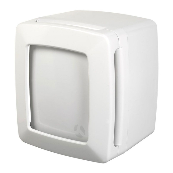
Installation and Operating Guide
LOOVENT eco
LOOVENT eco T – Timer (
LOOVENT eco HT – Humidity Timer (
LOOVENT eco MST – Motion Sensor Timer (
LOOVENT eco dMEV – Continuous Ventilation (
Economical to operate
Very quiet running fan
Low SFP
Compact design
Longer life Ball Bearing Motor
Simple replacement of existing Loovent
Read before commencing installation. Please leave these
instructions for the occupier
Centrifugal Fans
72684305)
72684306)
72684307)
1
80000110 Issue 4 – 05/13
72684308)
Advertisement

Related Manuals for Airflow LOOVENT eco T


Summary of Contents for Airflow LOOVENT eco T
- Page 1 80000110 Issue 4 – 05/13 Installation and Operating Guide LOOVENT eco Centrifugal Fans LOOVENT eco T – Timer ( 72684305) LOOVENT eco HT – Humidity Timer ( 72684306) LOOVENT eco MST – Motion Sensor Timer ( 72684307) LOOVENT eco dMEV – Continuous Ventilation ( 72684308) ...
- Page 2 The fan requires a suitable size hole through the wall or ceiling which connects to a duct venting to the outside. The external opening (100mm round hole) should be covered by a suitable grille, available separately from Airflow Developments Ltd. LOOVENT eco Functionality: INTERMITTENT VENTILATION ...
-
Page 3: Mechanical Installation
2. Mechanical Installation The LOOVENT eco fan range can be surface mounted or recessed in a wall or ceiling in a vertical or horizontal position (not suitable for window installation). Dimensions Figure 2 Figure 4 Figure 3 Front Cover Removal The front cover of the fan has a snap type fitting. - Page 4 90% of its possible length in order to maintain the best possible airflow (Figure 12). Ensure that flexible duct connections are not over tightened to the fan outlet spigot. To avoid reduced flow, an elbow plenum (optional Airflow Part # 52641301) should be used for all installations which contain bending of ducting.
-
Page 5: Electrical Installation
An external gravity flap Figure 14 Figure 15 grille may be used if required. (optional – Airflow Part #51791101) Restrictor Cone The Continuous Ventilation dMEV model is Supplied with a restrictor cone to increase the air velocity. - Page 6 TIP: When inserting the fan module into the body, locate the rectangular holes in the fan housing on the lugs in the base, holding the left hand side of the fan module slightly raised (as viewed in Figure 7 on Page 3). Lower the fan module gently until the retaining screws touch their respective inserts. Start one of the screws (one turn only) and then engage and tighten the second screw, applying a gentle pressure to the top of the rectangular moulding.
- Page 7 CONTROLS: VENTILATION CONTROL selects the The RUN TIME control is used to adjust the mode of operation of the fan. time period that the fan will operate for (or remain in boost mode) after being In CONTINUOUS mode (dMEV version triggered.
-
Page 8: Troubleshooting
Range of Accessories Available AIRFLOW DEVELOPMENTS Limited reserves the right in the interest of continuous development to alter any or all specifications without Prior notice. All orders are accepted subject to our conditions of sale which are available on request.