Table of Contents
Advertisement
Quick Links
TECHNICAL DATA
&
SERVICE MANUAL
With Virus Washer Function
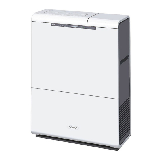
Space Cleaning System
Floor-mounted model
I
VW-VF10BG
RoHS
G
This product does not contain any hazardous substances prohibited by the RoHS Directive.
WARNING
G
You are requested to use RoHS compliant parts for maintenance or repair.
G
You are requested to use lead-free solder.
854-6-4849-256000
SM830156
REFERENCE No.
1
2
3
4
5
6
7
8
Advertisement
Chapters
Table of Contents

Related Manuals for Sanyo VW-VF10BG


Summary of Contents for Sanyo VW-VF10BG
-
Page 1: Technical Data
& SERVICE MANUAL With Virus Washer Function Space Cleaning System Floor-mounted model VW-VF10BG RoHS This product does not contain any hazardous substances prohibited by the RoHS Directive. WARNING You are requested to use RoHS compliant parts for maintenance or repair. -
Page 2: Safety Information
IMPORTANT Safety Information Be sure to read the following important safety information for safe and correct use of the product. The items listed here represent important information related to safety. The indicators and their meanings are as shown below. Incorrect handling or use may result in death or serious injury to the user. WARNING CAUTION Incorrect handling or use may result in injury to the user, or in property damage. -
Page 3: Important Information
CAUTION Do not place any containers that Do not perform cleaning while the Do not obstruct the outlet. contain liquid on top of the system is operating. Do not obstruct the air outlet with a curtain, system. Doing so may result in electric shock or towel, or other item. -
Page 4: Table Of Contents
CONTENTS Section 1: Features ............1-1 1. -
Page 5: Features
Features CONTENTS 1. FEATURES 1. System Features ............1-2 1. -
Page 6: System Features
Features 1. System Features 1. Air cleaning using electrolyzed water The combination of electrolyzed water with the Virus Washer element creates a “virus washer” function which is able to remove airborne viruses and bacteria from the air. 2. What is electrolyzed water? When tap water is electrolyzed it becomes electrolyzed water that contains electrolyzed hypochlorous acid, a chemical that has a disinfecting effect. - Page 7 Features 2. Unit built-in control section CHILD LOCK lamp CHILD LOCK button ON/OFF button DRAIN/DRY lamp Operating mode FAN SPEED button Indicates the fan speed. Press this button to change DRAIN/DRY button the fan speed. FILTER RESET button LOUVER button 3.
-
Page 8: Using This System
Using this System CONTENTS 2. USING THIS SYSTEM 1. Before Using this System ..........2-2 1. -
Page 9: Before Using This System
Using this System 1. Before Using this System Checking the installation location Do not install the system in the following locations: Ensure the space around the unit that is shown in the figure below. Near curtains, or on carpets These items can obstruct the intake and outlet, and can Minimum 100 cm cause system malfunction. - Page 10 Using this System After setting the electrolysis condition, re-install the front upper panel. First engage the bottom hooks, then press simultaneously at the points marked “PUSH” on the top left and right of the panel. A “click” sound should be heard. Chlorine (disinfectant) odor When this product is first used, there may be a disinfectant odor when operation starts.
-
Page 11: Filling The Water Tank
Using this System 2. Filling the water tank Fully tighten the cap. The water supply is necessary in order to generate electrolyzed water. Fill with water to this point. CAUTION Fill the water tank with new tap water every day, and keep the tank clean at all times. -
Page 12: Precautions For Use
Using this System 2. Precautions for Use 1. Before use Before using the system, the dealer must set the electrolysis condition setting to match the tap water that is used in the customer’s region. Refer to “Setting the electrolysis condition.” Note: “Save”... -
Page 13: Using The System
Using this System 3. Using the System Plug the power cord into the outlet. (Use an AC 220 – 240 V outlet.) Important Information Use a power source that includes a power leakage breaker. Selecting operation Press and hold this button for 3 seconds in order to engage the child lock. The CHILD LOCK CHILD lamp lights. -
Page 14: Draining Procedure
Using this System 4. Draining Procedure Water is automatically drained to the drainage tank in order to prevent fouling of the electrolyzed water inside the product and to maintain the Virus Washer capability. When the DRAIN lamp lights, follow the procedure below and dispose of the water in the drainage tank. -
Page 15: Draining And Drying Procedure
Using this System 5. Draining and Drying Procedure Perform draining and drying if the system is relocated or stored without being operated for a long period of time. Draining and drying procedure Set the fan speed to be used for drying. After setting the fan speed to “High,”... -
Page 16: Troubleshooting
Using this System 6. Troubleshooting 1. Error notification The CHECK lamp on the display blinks to indicate an error. For servicing, contact the dealer where the system was purchased. 2. The following conditions are not malfunctions. Before requesting servicing, check the following. If the problem is still not corrected, contact the dealer where the system was purchased. -
Page 17: Trouble Diagnosis
Using this System 7. Trouble Diagnosis Problems and locations to inspect Alarm display Alarm Alarm Inspection location Alarm Probable cause Correction code description / method LD005 LD006 (Does not The power supply to the Check that the power Turn the breaker ON. –... -
Page 18: Cleaning The System
Using this System 8. Cleaning the System Perform cleaning of the system regularly. If the system becomes particularly dirty, performance may decline, the system may malfunction, or odors may occur. WARNING Unplug the power cord when cleaning the system. Do not use chlorine-based or acidic detergents when cleaning the water tank, unit, or filters. Before cleaning Cleaning the unit (when it is dirty) Be sure to stop operation and unplug the... -
Page 19: Storage (When The System Will Not Be Used For An Extended Period Of Time)
Using this System Cleaning the outlet filter and intake filter (when dust becomes noticeable or when the FILTER lamp is ON) Outlet filter Remove the front upper panel and remove the outlet filter. Use a vacuum cleaner to remove the dust, then re-install the filter with the top side of the filter facing upwards. Outlet filter Front upper panel Pre-filter and high collection filter... -
Page 20: Replacing Consumable Parts
Using this System 10. Replacing Consumable Parts Replacing the electrolysis tank (when the OPERATION and CHECK lamps are blinking simultaneously) Replace the electrolysis tank (at charge to the customer). Request replacement from the dealer where the system was purchased. Electrolysis tank ··· After about 8 years (assuming 12 hours of use per day and setting at medium (MED) fan speed) If you continue to use the product without replacing the electrolyzing unit, the electrolyzed water concentration will decrease and performance will decline. -
Page 21: Declaration Of Conformity
Using this System Replacing the scale filters Water tank When the FILTER lamp lights, wash the scale filters. If the filters are particularly dirty, replace them with new filters Insert filters (at charge to the customer). facing in this The scale filters can be replaced by the customer, direction. -
Page 22: Measuring The Water Sample
Measuring The Water Sample CONTENTS 3. MEASURING THE WATER SAMPLE 1. Measuring the Electrolyzed Water Concentration ......3-2 2. -
Page 23: Measuring The Electrolyzed Water Concentration
Measuring The Water Sample 1. Measuring the Electrolyzed Water Concentration Adjust so that the electrolyzed water concentration is within the prescribed range in order to maintain the performance of the space cleaning system. (1) Preparing to measure the concentration After replacing the Virus Washer element and scale filters, and after cleaning the electrolyzed water tray, fill the water tank with water and install it in the unit. - Page 24 Measuring The Water Sample (5) When the zero-check is completed, add the reagent into the residual chlorine meter container, then mix well for approximately 20 seconds. Add the total chlorine reagent that was specified by the manufacturer of the residual chlorine concentration meter. (6) Place the container into the residual chlorine meter again and measure the concentration.
-
Page 25: Electrolyzed Water Concentration Measuring Tools
Measuring The Water Sample 2. Electrolyzed Water Concentration Measuring Tools Prepare the following instruments, parts, and materials before starting. (1) Residual chlorine concentration meter (5) 10 mL syringe (Example: Pocket calorimeter produced by Hach) (for purified water: used to dilute the concentration) (2) Total chlorine reagent (6) 1 mL syringe (Reagent designated by the manufacturer of the... -
Page 26: Specifications
Specifications CONTENTS 4. SPECIFICATIONS 1. Product Specifications ........... 4-2 2. -
Page 27: Product Specifications
Specifications 1. Product Specifications Model name Virus Washer System (Floor-Mounted) General Model No. VW-VF10BG Height External Width dimensions Depth Net weight Operating weight 39 (when water tank is full) Shipping weight Shipping volume 0.24 Water tank capacity Approx. 6 Front panel: NW-K11 (VW white), Munsell value N8.5 Exterior color (Munsell number) –... -
Page 28: Part Specifications
Specifications 2. Part Specifications Fan motor coil resistance Model No. DK8-63F280H Resistance Red – White 26.6 (Ω Ω ) White – Blue 26.6 (at 20°C) Blue – Red 26.6 Thermistor characteristics Intake temperature sensor –30 –25 –20 –15 –10 –5 10 15 20 25 30 35 40 45 50 55 60 65 70 Temperature [°C] Electrolyzing unit water temperature sensor... -
Page 29: Schematic Diagram
Specifications 4. Electric Wiring Diagram 8FA-2-5250-140-00-2 SYMBOLS DESCRIPTION Electric Wiring Diagram Fan motor DRV2 Drain valve Drain pump FS (HAI) Float switch (FLUSH) Float switch 1 RY001 – 005, Relay THERMISTOR (ROOM Temp.) THERMISTOR (WATER Temp.) REACTOR ELTD-TRODE Electrode Louver motor Humidity sensor CR-VF10B Control PCB... -
Page 30: Pcb And Functions
PCB and Functions CONTENTS 5. PCB AND FUNCTIONS 1. Explanation of Functions ..........5-2 1. -
Page 31: Explanation Of Functions
PCB and Functions 1. Explanation of Functions 1. Control PCB (CR-VF10B) LED display Control PCB Control section Louver motor plug (LD005) power plug (CN020) D plug (CN036) (CN016) Electrolysis Display section Control section LED display plug (CN019) plug (CN035) B plug (CN037) (LD006) Electrode plug (CN021) -
Page 32: Power Pcb (Pow-Vf10Bg)
PCB and Functions 2. Power PCB (POW-VF10BG) 250V AC 5A AC IN (F201) (CN201) 3. Fan PCB (FAN-VF10B) Fan motor plug (CN301) 5 - 3... -
Page 33: Display Section Pcb (Ind-Vf10B)
PCB and Functions 4. Display Section PCB (IND-VF10B) IND-D (CN401) 5. Control Section PCB (SW-VF10B) Drain / Dry switch Louver switch Fan speed switch SW-B plug (SW504) (SW503) (SW502) (CN502) Child lock switch Filter-Reset switch Operation ON / OFF switch SW-D plug (SW505) (SW506) -
Page 34: Clearing The Total Times (Filter, Water Change, Electrolyzing Unit Change)
PCB and Functions 2. Clearing the Total Times (Filter, Water Change, Electrolyzing Unit Change) Follow the procedure below to clear (reset) the total times for filter cleaning, water change, and electrolyzing unit change after servicing and maintenance are completed. 1. Clearing the total times for filter and water change Step 1 Short-circuit maintenance pin 1 on the control PCB. -
Page 35: Turning The Buzzer On/Off
PCB and Functions 3. Turning the Buzzer ON/OFF The system contains a buzzer that sounds to inform the user when water must be added. This buzzer can be turned ON/OFF by means of setting item code “83” on the control PCB EEPROM. Setting data 00: Buzzer ON (setting at time of shipping from the factory) 01: Buzzer OFF... -
Page 36: Changing The Cleaning Monitor Display
PCB and Functions 4. Changing the Cleaning Monitor Display The cleaning monitor display can be changed by means of setting item code “88” on the control PCB EEPROM. Setting data 00: Standard display (setting at time of shipment from the factory) 01: Humidity indicator 02: Blinking line display when cleaning indicator is full 03: Blinking line display when humidity indicator and cleaning indicator are full... -
Page 37: Maintenance Procedures
Maintenance Procedures CONTENTS 6. MAINTENANCE PROCEDURES 1. Diagram of Functional Parts ..........6-2 2. -
Page 38: Diagram Of Functional Parts
Maintenance Procedures Before beginning work, stop the system and be sure to unplug the power cord from the outlet. 1. Diagram of Functional Parts Water tank Virus Washer Electrolysis tank element Filter Float switch Intake temperature Circulation pump sensor Fan motor High collection filter Pre-filter... -
Page 39: Maintenance Procedure
Maintenance Procedures 2. Maintenance Procedure 1. Replacing the Virus Washer element The Virus Washer element must be periodically replaced. It is possible for the customer to replace the element, however a regular maintenance contract is recommended. The Virus Washer element must be replaced (at charge to the customer) once a year. Contact the dealer where the system was purchased. - Page 40 Maintenance Procedures Disconnect the joint from the Visur Washer element. Press on the stopper at the base of the joint while pulling Joint the joint upward to remove it. Securely attach the removed joint to the new Virus Washer element. Stopper CAUTION If the joint is not securely attached, water leakage will occur.
-
Page 41: Replacing The Electrolysis Tank
Maintenance Procedures 2. Replacing the electrolysis tank Stop the system and unplug the power cord. Remove the top and bottom parts of the front panel. Remove the water tank, and remove divider panels A and B (4 screws each). Remove the electrical component box cover (4 screws). Electrical component box cover Divider panel A... - Page 42 Maintenance Procedures Remove the top joint and left-side joint from the electrolysis tank unit. To remove the joint, press the stopper at the base of each joint while pulling on it. Stopper Press Press Remove the electrolysis tank unit together with the installation bracket (3 screws).
-
Page 43: Replacing The Circulation Pump
Maintenance Procedures 3. Replacing the circulation pump Perform steps – from “Replacing the electrolysis tank.” Disconnect the circulation pump cord from the cord clip. Circulation pump cord Cord clip Cut the binding bands (2) inside the electrical component box, then open the cord clips (2) and disconnect the circulation pump connector. -
Page 44: Replacing The Float
Maintenance Procedures 4. Replacing the float Perform steps – from “Replacing the circulation pump.” Disconnect the drain float switch connector. Binding band Drain float switch connector FS (HAISUI) Loosen the float switch installation nut on the float switch installation bracket, then remove the float switch. Float switch installation bracket Float switch installation nut Float switch... -
Page 45: Replacing The Fan Motor
Maintenance Procedures 5. Replacing the fan motor Stop the system and unplug the power cord. Remove the top and bottom parts of the front panel, and remove the cover from the electrical component box (4 screws). Remove the pre-filter and high collection filter. Remove installation brackets A, B, C, and D (8 screws), and remove the filters from them. -
Page 46: Replacing The Room Temperature Sensor
Maintenance Procedures 6. Replacing the room temperature sensor Perform steps – from “Replacing the fan motor.” Disconnect the room temperature sensor cord from the cord clip, then cut the binding bands (2) inside the electrical component box, and disconnect the room temperature sensor connector. Binding bands Cord clip Room temperature sensor connector (TA) -
Page 47: Replacing The Humidity Sensor
Maintenance Procedures 7. Replacing the humidity sensor Perform steps – from “Replacing the fan motor.” Disconnect the humidity sensor cord from the cord clip, then cut the binding bands (2) inside the electrical component box, and disconnect the humidity sensor connector. Binding bands Cord clip Humidity sensor connector (HU) -
Page 48: Cleaning The Electrolyzed Water Tray
Maintenance Procedures 8. Cleaning the electrolyzed water tray Stop the system and unplug the power cord. Water tank Remove the water tank. Remove the front upper panel, then remove the divider panel A (4 screws). Insert facing in this direction. Remove the scale filters. -
Page 49: Replacing The Solenoid Valves
Maintenance Procedures 10. Replacing the solenoid valves Stop the system and unplug the power cord. Remove the top and bottom parts of the front panel. Remove the water tank. Remove the divider panel A (4 screws), then remove the electrolyzed water tray cover (2 screws) and remove the electrical component box cover (4 screws). - Page 50 Maintenance Procedures Replace the solenoid valve. (1) Cut the binding bands (2) inside the electrical component box, then disconnect the solenoid valve connector and remove the cord from the clamps (2). Binding bands Solenoid valve connector (DRV1) Clamps Cord clip (2) Remove the solenoid valve installation bracket A (2 screws), then disconnect the transparent tube from the left joint.
-
Page 51: Replacing The Pcbs Inside The Electrical Component Box
Maintenance Procedures 11. Replacing the PCBs inside the electrical component box Stop the system and unplug the power cord. Remove the top and bottom parts of the front panel. Remove the electrical component box cover (4 screws). Disconnect all cords that run into the electrical component box. - Page 52 Installation CONTENTS 7. INSTALLATION 1. Accessories ............7-2 2.
-
Page 53: Installation
Installation 85464369020000 Installation For the Person in Charge of Installation VW-VF10BG 1. Accessories Part Name Figure Q’ty Remarks Chain For preventing unit tip-over Measuring spoon For measuring salt (1 g) Safety Precautions I Read the “Safety Precautions” carefully before performing installation or electrical work, and perform the work correctly. -
Page 54: Installation Location
Installation 2. Installation Location 1. Install in a location where air circulates easily. Make sure that there are no objects obstructing the flow of air at the Minimum 100 cm intake and outlet. 2. Be sure to ensure the space around the unit as shown in Minimum the figure at right. -
Page 55: Installation Procedure
Installation 3. Installation Procedure Be sure to take the necessary steps to prevent the unit from tipping over. Use the provided chain. There is a screw located at the top rear of the unit for this purpose. (1) Remove the screw. (2) Pass the chain through the screw, then tighten the chain together with the screw in the original screw hole. -
Page 56: Test Run
Installation Test Run I Test run 1. Be sure to set the electrolysis condition. (Refer to the Instruction Manual.) 2. Fill the water tank all the way with tap water. Be sure to use normal tap (drinking) water. Never use water from a water purifier, water from a water heater, alkali ion water, mineral water, well water, seawater, or similar types of water. -
Page 57: Miscellaneous
Miscellaneous CONTENTS 8. MISCELLANEOUS 1. Maintenance of Virus Washer by Customer ........8-2 2. -
Page 58: Maintenance Of Virus Washer By Customer
Miscellaneous 1. Maintenance of Virus Washer by Customer Applicable model: VW-VF10BG 1. When the ADD WATER lamp lights 3. When the FILTER lamp lights (Every day: Approx. 10 hours of operation at Med. fan speed) (Every 1 or 2 months) When there is no water in the water tank, the system stops The FILTER lamp (red) lights in the display every 1 or 2 months. -
Page 59: Pack Test
Miscellaneous 2. Pack Test Measuring Method for Pack Test of Tap Water Hardness How to Measure “TH” indicated on the tab of the tube Pull out 30 seconds Remove the green Turn the tube with the open While keeping the tube Shake the tube lightly 5 or 6 times. - Page 60 Miscellaneous Measuring Method for Chloride Pack Test How to Measure Pull out “Cl(D)” indicated 1 drop on the tab of the tube Shake 1. Fill the vial up to the first line 2. Put on the cap and shake Pull out the plastic stick from the end of the tube (1.5ml) with the water sample.