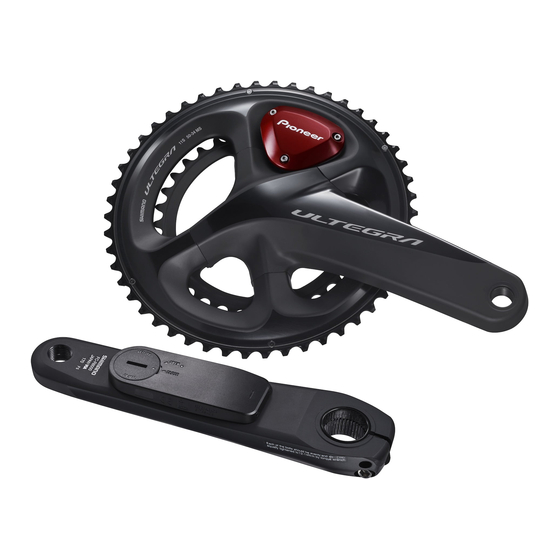
Pioneer SGY-PM910H Installation Manual
Pedaling monitor sensor
Hide thumbs
Also See for SGY-PM910H:
- User manual (112 pages) ,
- Important information for the user (60 pages)

Related Manuals for Pioneer SGY-PM910H


Summary of Contents for Pioneer SGY-PM910H
- Page 1 Installation Manual (for dealers) Pedaling Monitor Sensor SGY-PM910H Please read the Important Information for the User in the product box for product warnings and other important safety information.
-
Page 2: Table Of Contents
Table of Contents Introduction Pairing and Calibrating Features ..............3 Before Pairing and Calibrating ........ 18 Manuals ................3 Pairing and Calibrating Procedure .........18 Compatibility .............. 4 Placing the Bicycle in a Secure Work Position ....18 Pairing the Pedaling Monitor Sensor ....... 19 Getting Ready Specifying the Device Number to Pair it ......21 Checking Device Numbers ..........22... -
Page 3: Features
• Installation Manual (for dealers): [For American Users] http://www.pioneerelectronics.com [For Canadian Users] http://www.pioneerelectronics.ca [For European Users] http://www.pioneer.eu Explains details about handling methods. The product installation methods (for dealers) are also described as references. • Important Information for the User: Important Information for the User provides detailed information related to safety. -
Page 4: Compatibility
Compatibility „ Crank sets The product is compatible with the following crank sets. Crank sets Remarks • SHIMANO FC-9000 Crank lengths of 165 mm, 167.5 mm, 170 mm, 172.5 mm, 175 mm, crank set of 50-34T, 52- 36T, 52-38T, 53-39T, 54-42T, 55-42T are compatible. * •... -
Page 5: Product Configuration
Product Configuration Accessories This product contains the following parts. Pedaling monitor sensor (right side) Right transmitter Junction cable Strain gauge unit Junction box Pedaling monitor sensor part (right side) For FC-9000 Chain ring adapter For FC-6800 Strain gauge unit cover x 1 for each type Pedaling monitor sensor (left side) Left transmitter Strain gauge unit... -
Page 6: Before Starting Installation
Before Starting Installation Installing, pairing, and calibrating the product requires specialized techniques and tools. Ask the shop where you bought the product to install, pair, and calibrate it. Installation Procedure The product is installed in the order shown here. Checking operation of the sensors (page 7) Installing the magnet rings (page 9) Calibrating the magnets and fixing them in place (page 15) Eliminating Static Electricity during Installation... -
Page 7: Checking Operation Of The Sensors
Checking Operation of the Sensors Before installing the sensors, confirm that they operate correctly. Remove the right transmitter’s cover. Use a hex wrench (2 mm) to loosen the screw and remove the cover. • Be careful not to lose the removed screw. Remove the left transmitter’s cover. - Page 8 Checking Operation of the Sensors Push the push switch in the right transmitter for less than 2 seconds to confirm the sensor mode is set to the pedaling monitor mode. By pushing the push switch in the right transmitter for less than 2 seconds, the LEDs on the right transmitter blink green. After that, if the LEDs light green for 10 seconds, the sensor is set to pedaling monitor mode.
-
Page 9: Installing The Magnets
Installing the Magnets Install the magnets on the bicycle. There are two types of magnets, install one type on the bicycle. Checking the Position of the Magnets and Magnetic Sensors This system measures the rotations of the cranks by magnets passing over magnetic sensors in the left and right transmitters. Check the position of the magnets and the left and right magnetic sensors before installing the magnets on the bicycle. - Page 10 Installing the Magnets Select a type of magnet according to the following table. Crank Position to measure Measured results Type of magnet Distance between chainring adapter and chain stay Over 4.5 mm Patch type Under 9.1 mm Right (*1) Over 1.5 mm Arm type Distance between left transmitter and chain stay Over 6 mm...
-
Page 11: Installing Patch Type Magnets
Installing the Magnets Installing Patch Type Magnets This section explains how to Install patch type magnets (temporarily). The left crank is used as an example for this explanation, but the right crank uses the same procedure. • If the position in which you will install the patch type magnet is dirty, remove any dirt with cleaner before you install it. •... - Page 12 Installing the Magnets Temporarily install the magnet on the chain stay. Install the magnet on the chain stay so it is positioned on the circle confirmed in step 2. • Guideline for installation position (position over which magnetic sensors pass) Left side: Position on a radius about 53 mm from the center of the BB Right side: Position on a radius about 42 mm from the center of the BB Slowly rotate the crank set one rotation.
-
Page 13: Installing Arm Type Magnets
Installing the Magnets Installing Arm Type Magnets This section explains how to install arm type magnets (temporarily). The left side of the bicycle is used as an example for this explanation, but the right side uses the same procedure. • The position of the arm type magnets must be checked periodically. - Page 14 Installing the Magnets Slowly rotate the crank set one rotation. Confirm that the magnets do not interfere with the crank, transmitter or chainring adapter. • Use a pair of snips to cut the excess parts off the magnet's cable ties if they interfere with the crank, transmitter or chainring adapter. When you do this, remember to leave a long enough piece of the cable tie so you can tighten it.
-
Page 15: Calibrating The Magnets And Fixing Them In Place
Calibrating the Magnets and Fixing Them in Place Switch the sensors to magnet calibration mode, then confirm that the temporarily attached magnets are operating correctly. After you confirm the magnets are operating correctly, fix the magnets in place and then calibrate them. •... - Page 16 Calibrating the Magnets and Fixing Them in Place Fix the magnets in place. Be careful not to move the magnets from their adjusted positions when you fix them in place. • Arm type Use needle nose pliers to tighten the cable ties to fix the magnets in place, then use snips to cut off the excess parts of the cable ties.
- Page 17 Calibrating the Magnets and Fixing Them in Place Install the right transmitter’s cover. Use a tool to measure the torque when you tighten the screws on the right transmitter’s cover. • Tightening torque: 30 cN•m • Install the cover firmly to ensure water resistant performance. This completes the calibration of the magnets and fixing them in place.
-
Page 18: Before Pairing And Calibrating
Before Pairing and Calibrating This section describes how to pair and calibrate the pedaling monitor sensor that is installed on the bicycle to the Cyclocomputer SGX-CA500. • See the User’s Manual or the User’s Guide (online manual) of the Cyclocomputer SGX-CA500 regarding how to operate it. Pairing and Calibrating Procedure Use the following procedure to pair and calibrate the product. -
Page 19: Pairing The Pedaling Monitor Sensor
Pairing the Pedaling Monitor Sensor This section describes how to pair the pedaling monitor sensor to the Cyclocomputer SGX-CA500. It is necessary to pair the sensors on both the left and right sides. The right-side pedaling monitor sensor is used as an example in this description. - Page 20 Pairing the Pedaling Monitor Sensor Tap [Device Type] and then [Pedaling Monitor R]. A list appears when you tap [Device Type]. Scroll down the list and then tap [Pedaling Monitor R]. • For the left pedaling monitor sensor, press [Pedaling Monitor L]. Tap [Search].
-
Page 21: Specifying The Device Number To Pair It
Pairing the Pedaling Monitor Sensor Specifying the Device Number to Pair it To specify the device number of the sensor, do the following procedure before searching for the sensor. Check [Specified Search] in the sensor’s pairing menu. Tap [Device Number]. Enter the device number and tap •... -
Page 22: Checking Device Numbers
Pairing the Pedaling Monitor Sensor Checking Device Numbers Device numbers are used when you specify the sensor’s device number to pair it to the Cyclocomputer. Left side: Transmitter Right side: Junction box Device number... -
Page 23: Calibrating The Zero Point
Calibration Calibrating the Zero Point This section describes how to use the Cyclocomputer SGX-CA500 to calibrate the zero point of the pedaling monitor sensor that is installed on the bicycle. Zero point calibration is a function to store the zero point (no-load), where no forces act on the crank, in the sensor memory. -
Page 24: Checking The Calibration
Checking the Calibration Check that the sensors were calibrated correctly. It is necessary to check the calibration of the sensors on both the left and right sides. The right-side pedaling monitor sensor is used as an example in this description. The procedure to check the left side is the same as for the right side. Position the crank arm so it is perpendicular to the ground, pointing downward. -
Page 25: Troubleshooting
Troubleshooting Refer to the following suggestions if you have any problems installing or using the product. If you cannot solve the problem, please contact your dealer or visit our web site. „ Installation Solution Symptom Cause User Dealer Take your bicycle to your retailer and have its size measured to check whether A sensor installed on the crank The frame is not supported. - Page 26 Troubleshooting „ Magnet Solution Symptom Cause User Dealer ― I cannot install the magnet on The installation of the magnet There are two types of magnets, patch the chainstay. or the selected magnet type is type and arm type. incorrect. You need to choose the appropriate type depending on the distance between the magnet and the left...
- Page 27 Troubleshooting „ Sensor Connection Solution Symptom Cause User Dealer The pedaling monitor The sensor is in sleep state. Activate the transmitter by rotating the bicycle’s crank set at least three times. The sensor automatically enters a sleep state if it is still for five minutes. sensor cannot pair to the Confirm that the batteries (CR2032, 3V) are correctly installed in the left and Cyclocomputer.
- Page 28 Troubleshooting Solution Symptom Cause User Dealer The pedaling monitor sensor in The other company’s Check that the Cyclocomputer being used supports pairing with the ANT+ the power meter mode cannot cyclocomputer does not power meter. pair to a different company’s support ANT+ power meter.
- Page 29 Troubleshooting Solution Symptom Cause User Dealer The torque chart is not near 0 There are loads on the cranks Position either the left or right crank at 6 o’clock before calibrating from the N after calibrating zero point in or pedals. Cyclocomputer.
- Page 30 Troubleshooting Solution Symptom Cause User Dealer The vector data does not The sensor and Cyclocomputer The sensor information may not be received correctly, depending on the radio wave environment. Confirm it in a location that has a good radio wave update every few seconds.
-
Page 31: Error Codes
Troubleshooting Error codes An error code is displayed if an error occurs while setting the crank length or doing calibrations. Code Description of error Data (radial) Data (tangential) Parameter deviation (mass of load is 0) Insufficient battery power Failed to calibrate zero point (tangential and radial) 1: Error 1: Error 0: Normal... -
Page 32: Assembling The Chainring And Installing The Right Transmitter
Assembling the Chainring and Installing the Right Transmitter Install the right transmitter on the right crank as you assemble the chainring. If the chainring and chainring adapter have been removed, assemble the chainring and fasten the right transmitter according to the following procedure. - Page 33 Assembling the Chainring and Installing the Right Transmitter Insert the chainring bolts into the bolt holes and temporarily install the chainring adapter on the chainring. Do not tighten the chainring bolts too tightly when you temporarily tighten them. Press on the chainring in a clockwise direction to eliminate any play as you tighten the chainring bolts to the specified torque.
-
Page 34: Care, Maintenance, And Storage
Care, Maintenance, and Storage • Use a soft dry cloth or a cloth that has been dampened and wrung out to wipe dirt from the left and right transmitters, the strain gauge unit cover, the magnet, and other accessories. • Do not use benzene, paint thinner, or other volatile chemicals, cleansers, or chemically treated cloths. -
Page 35: Specifications
Specifications Weight: About 66 g Dimensions: Pedaling monitor sensor (right side): • Right transmitter: 58.3 mm(W) × 46.1 mm(H) × 21.3 mm(D) • Junction box, Strain gauge unit cover: 78 mm(W) × 36.7 mm(H) × 7.3mm(D) Pedaling monitor sensor (left side): 92.5 mm(W) ×... - Page 36 Visit www.pioneer.eu to register your product. Visitez www.pioneer.eu pour enregistrer votre appareil. Si prega di visitare il sito www.pioneer.eu per registrate il prodotto. Visite www.pioneer.eu para registrar su producto. Zum Registrieren Ihres Produktes besuchen Sie bitte www.pioneer.eu. Bezoek www.pioneer.eu om uw product te registreren.