IBM Midrange System DS4000 Series Hardware Manual
Midrange system storage ds4000/ds5000 series
Hide thumbs
Also See for Midrange System DS4000 Series:
- Hardware maintenance manual (184 pages) ,
- Installation and user manual (84 pages) ,
- Planning and installation manual (44 pages)
Table of Contents
Advertisement
Quick Links
IBM Midrange System
Storage Hardware Guide
DS4000 and DS5000 hardware
planning and configuration
Remote Support Manager (RSM)
configuration
Features of Storage Manager
V10.60
ibm.com/redbooks
Front cover
Sangam Racherla
Bruce Allworth
Alessio Bagnaresi
Chris Bogdanowicz
Corne Lottering
Pablo Pedrazas
Frank Schubert
John Sexton
Alexander Watson
Advertisement
Table of Contents

Related Manuals for IBM Midrange System DS4000 Series


Summary of Contents for IBM Midrange System DS4000 Series
-
Page 1: Front Cover
Front cover IBM Midrange System Storage Hardware Guide DS4000 and DS5000 hardware planning and configuration Remote Support Manager (RSM) configuration Features of Storage Manager V10.60 Sangam Racherla Bruce Allworth Alessio Bagnaresi Chris Bogdanowicz Corne Lottering Pablo Pedrazas Frank Schubert John Sexton Alexander Watson ibm.com/redbooks... - Page 3 International Technical Support Organization IBM Midrange System Storage Hardware Guide March 2010 SG24-7676-01...
- Page 4 Second Edition (March 2010) This edition applies to: IBM Midrange System Storage running V7.60 firmware. IBM DS Storage Manager V10.60. © Copyright International Business Machines Corporation 2010. All rights reserved. Note to U.S. Government Users Restricted Rights -- Use, duplication or disclosure restricted by GSA ADP Schedule...
-
Page 5: Table Of Contents
1.5 IBM Midrange System Storage hard disk drives ....... 9... - Page 6 3.9.1 EXP5000 and EXP520 Storage Expansion Unit ......99 Chapter 4. IBM System Storage DS planning and configuration ....103 4.1 Planning your DS storage structure .
- Page 7 4.6.4 Storage Manager utilities ......... . 152 4.7 Installing IBM System Storage DS Storage Manager ......152 4.7.1 Installing Storage Manager in a Windows Server 2008 host .
- Page 8 6.1 IBM Remote Support Manager for Storage....... . . 286...
- Page 9 8.2.2 Embedding commands in batch files ....... . . 503 Appendix A. Overview of IBM System Storage DS5000 RAID types ... . . 505...
- Page 10 Other iSCSI performance considerations ........525 Appendix C. Solid State Drives on the IBM System Storage DS5000 series..527 SSD technology .
- Page 11 IBM representative for information on the products and services currently available in your area. Any reference to an IBM product, program, or service is not intended to state or imply that only that IBM product, program, or service may be used. Any functionally equivalent product, program, or service that does not infringe any IBM intellectual property right may be used instead.
- Page 12 IBM at the time this information was published. Such trademarks may also be registered or common law trademarks in other countries. A current list of IBM trademarks is available on the Web at http://www.ibm.com/legal/copytrade.shtml...
- Page 13 This publication is designed specifically to address the hardware features and configuration of the IBM Midrange System Storage servers and can be used in conjunction with the following IBM Midrange System Storage Redbooks publications: IBM Midrange System Storage Implementation and Best Practices Guide, SG24-6363...
- Page 14 NUMA-Q® technology. He remained in a support role when Sequent merged with IBM in 1999. He is currently a member of the IBM MTS SAN and midrange storage hardware support team in the UK. In addition, he is part of a Virtual EMEA Team (VET), providing Level 2 support for DS4000 and DS5000 products in Europe.
- Page 15 John Sexton is a Certified Consulting IT Specialist, based in Auckland, New Zealand, and has over 20 years of experience working in IT. He has worked at IBM for the last 13 years. His areas of expertise include IBM System p, AIX, HACMP™, virtualization, storage, IBM Tivoli Storage Manager, SAN, SVC, and business continuity.
- Page 16 Follow us on twitter: http://twitter.com/ibmredbooks Look for us on LinkedIn: http://www.linkedin.com/groups?home=&gid=2130806 Explore new Redbooks publications, residencies, and workshops with the IBM Redbooks weekly newsletter: https://www.redbooks.ibm.com/Redbooks.nsf/subscribe?OpenForm Stay current on recent Redbooks publications with RSS Feeds: http://www.redbooks.ibm.com/rss.html IBM Midrange System Storage Hardware Guide...
- Page 17 8 Gbps FC host interface Remote Support Manager Hardware Model - RS2 Changed information Host Port Upgrade for DS5100 Cache Upgrade option for DS5100 and DS5300 448 Drive support for DS5100 and DS5300 © Copyright IBM Corp. 2010. All rights reserved.
- Page 18 IBM Midrange System Storage Hardware Guide...
- Page 19 This chapter introduces the IBM Midrange System Storage storage subsystems and positions them within the overall IBM System Storage Disk Systems (DS) family. The IBM Midrange System Storage storage subsystems include the IBM System Storage DS4000 and IBM System Storage DS5000 models. The current hardware models are briefly described, as well as the Storage Manager software.
-
Page 20: Positioning The Ds4000/Ds5000 Series
1.1 Positioning the DS4000/DS5000 series IBM has brought together into one family, known as the DS family, a broad range of disk systems to help small to large size enterprises select the right solutions for their needs. The DS family combines the high-performance IBM System Storage DS6000/DS8000 series of enterprise servers with the IBM System Storage DS4000 and DS5000 series of midrange systems, and other line-of-entry systems (IBM System Storage DS3000 series). -
Page 21: Chapter 1. Introduction To Ibm Midrange System Storage Storage Subsystems
The overall positioning of the DS4000/DS5000 series within the IBM System Storage DS family is shown in Figure 1-2. It expands the IBM Midrange System Storage offering in terms of performance and scalability. Entry level Midrange and high High-end and Enterprise Disk Systems systems –... - Page 22 At the time of writing one model is available: – Model 20A with 8 GB or 16 GB of cache memory and one of the combinations of host interfaces specified in the list above. IBM Midrange System Storage Hardware Guide...
- Page 23 One model is available: – Model 53A with 8 GB, 16 GB, 32 GB, or 64 GB of cache memory and one of the combinations of host interfaces specified in the list above. Chapter 1. Introduction to IBM Midrange System Storage storage subsystems...
-
Page 24: Ibm Midrange System Storage Expansion Enclosure
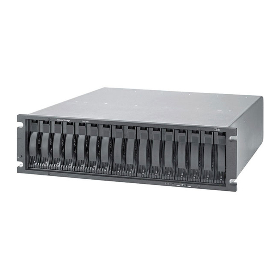
1.3 IBM Midrange System Storage expansion enclosure At the time of writing, the IBM Midrange System Storage expansion enclosures offer a 4 Gbps FC interface, and four models are available: EXP810 Expansion Enclosure This expansion unit is packaged in a 3U rack-mountable enclosure, supports up to 16 FC disk drives or E-DMM SATA drives. -
Page 25: Ibm System Storage Ds Storage Manager Software
EXP5060 storage expansion enclosures. 1.4 IBM System Storage DS Storage Manager software The IBM System Storage DS Storage Manager software (see Figure 1-3) is used to configure, manage, and troubleshoot the DS4000 and DS5000 storage subsystems. - Page 26 – Storage Management Initiative - Specification Provider (SMI-S Provider) An SMI-S provider is a vendor-specific module that is used so that independent management software, such as IBM TotalStorage® Productivity Center (TPC), can manage a vendor device using a standard interface based on the Common Information...
-
Page 27: Ibm Midrange System Storage Hard Disk Drives
1.5 IBM Midrange System Storage hard disk drives Every storage subsystem within the IBM Midrange System Storage series is a multi-tiered storage server that is capable of supporting multiple disk drive technologies even within the single expansion unit. This capability enables you to have a Total Cost of Ownership (TCO) reduction and a storage consolidation by putting together different workloads with different performance requirements. - Page 28 – 4 Gbps FC, 73.4 GB/15k rpm (only DS4000 models) – 4 Gbps FC, 146.8 GB/15k rpm – 4 Gbps FC, 300 GB/15k rpm – 4 Gbps FC, 450 GB/15k rpm – 4 Gbps FC, 600 GB/15k rpm IBM Midrange System Storage Hardware Guide...
-
Page 29: Iscsi Basics
All the DS5000 series models now support iSCSI host connectivity and in this section we briefly describe the basics of the iSCSI protocol. Consult Appendix B, “Deploying iSCSI host interface controllers on the IBM System Storage DS5000 series” on page 515 for more detailed information. -
Page 30: Fibre Channel Direct/Switch Basics
Fibre Channel (FC) is a high-speed disk attachment technology, designed to connect a large number of storage devices to a number of host servers across a Storage Area Network (SAN). Fibre Channel Protocol (FCP) transfers SCSI commands and data across physical FC links. IBM Midrange System Storage Hardware Guide... - Page 31 At the time of writing, the IBM Midrange System Storage series’ maximum FC throughput is 8 Gbps; 10 Gbps links can be used today, but only for SAN switch interconnection.
- Page 32 WWNs are somewhat similar to the MAC addresses in Ethernet terms. For example, each FC HBA has its own WWN, which is hardcoded (or burned-in) during manufacturing. The HBA will be uniquely identified by the storage subsystem using its WWN. IBM Midrange System Storage Hardware Guide...
-
Page 33: New Features
New features Chapter 2. This chapter provides a brief description about new features that are part of controller firmware version (CFW) 7.60 and the IBM System Storage DS5020 announcement. © Copyright IBM Corp. 2010. All rights reserved. -
Page 34: Full Disk Encryption Capable Disk Drive Modules (Ddm)
How do we place the right data on these (expensive) devices at the right time to achieve performance objectives without creating an undue burden of management? IBM DS5000 offers a 76 GB SSD drive running on 4 Gbps Fibre Channel (FC) that is compatible with the EXP5000. -
Page 35: Gb Fc Disk Drive Module
2.5 IBM System Storage DS5020 storage subsystem and EXP520 The IBM System Storage DS5020 storage system (Machine Type 1814-20A) is designed to provide solutions to meet the needs of midrange/departmental storage requirements, delivering high performance, advanced function, high availability, modular and scalable storage capacity. -
Page 36: Highlights
It supports an intermix of SATA drives, FC drives, and encryption-capable FC drives within the DS5020 and EXP520 enclosures. See Chapter 3, “IBM System Storage DS4000 and DS5000 hardware” on page 23 for more details about the DS5020 and EXP520. -
Page 37: Iscsi Host Interface
DS5020. iSCSI HICs for the DS53100 and DS5300 are available as field replacable upgrades (MES) that will be installed by trained IBM service personnel. See Chapter 3, “IBM System Storage DS4000 and DS5000 hardware” on page 23 for specific information about iSCSI on a particular DS5000 subsystem. -
Page 38: Remote Support Manager Hardware Model Rs2
Designed to manage up to 50 DS5000/DS4000/DS3000 storage systems per implementation Sends log and status information along with the alert to IBM for problem resolution Enables the IBM service support center to dispatch inquiries to determine problem and speed problem resolution For additional information about the DS-RSM, go to the following address: http://www-03.ibm.com/systems/storage/disk/rsm/index.html... -
Page 39: New Storage Manager Subsystem Management Window (Smw) Design
Support tab has been added to combine all the support activities together. Figure 2-1 gives an overview of this new design. See Chapter 4, “IBM System Storage DS planning and configuration” on page 103 for details about the new functions. - Page 40 IBM Midrange System Storage Hardware Guide...
- Page 41 This section details the DS5000 products, which include the DS5020, DS5100, and the DS5300. The DS4000 product covered in this section includes only the DS4700 model; for more details about the older DS4000 models, see IBM System Storage DS4000 and Storage Manager V10.30, SG24-7010.
-
Page 42: Ibm System Storage Ds4700 Express
3.1 IBM System Storage DS4700 Express The IBM System Storage DS4700 Express storage subsystem (Figure 3-1) uses 4 Gbps technology (4 Gbps capable drives and the HBAs required to achieve 4 Gbps throughput speeds). It is designed to handle the most rigorous customer workloads and can expand from workgroup to enterprise-wide capability with the attachment of six DS4000 EXP810 disk enclosures. -
Page 43: Chapter 3. Ibm System Storage Ds4000 And Ds5000 Hardware
RAID level migration, which allow users to modify storage configurations on-the-fly without incurring any downtime. New Remote Support Manager (RSM) support to notify IBM (Call Home) in case of problems or failures. See Chapter 6, “IBM Remote Support Manager for Storage” on page 285 for more details about RSM. -
Page 44: Ds4700 Model Comparison
3.3 DS4000 series expansion enclosures There are various models of expansion enclosures available for the DS4000 series. We provide a short description for the latest models; for more details, see IBM System Storage DS4000 and Storage Manager V10.30, SG24-7010. The models are: DS4000 EXP710 FC Expansion Enclosure with 2 Gbps Switched Disk Technology (This technology is also referred to as a Switched Bunch Of Disks (SBOD).) -
Page 45: Ibm Total Storage Ds4000 Exp710 Expansion Enclosure
Storage Manager V9.x and later. For additional information about drive migration and special handling procedures for expansion enclosures, see the IBM System Storage DS4000/DS5000 Hard Drive and Storage Expansion Enclosure Installation and Migration Guide, GC53-1139. -
Page 46: Intermixing Exp810 And Exp710
When intermixing the EXP810 and EXP710, even though the enclosure grouping by type is not a requirement, IBM recommends that you group them by enclosure type in a redundant drive channel pair to simplify maintenance and troubleshooting. Also, the EXP810 link rate switch must be set at 2 Gbps if you use them in the same dive channel. -
Page 47: Ds5100 And Ds5300 Storage Subsystems
New flash memory to store dirty data from cache during power outage. Two dedicated PCI Express buses for cache mirroring. Redundant, hot-swappable power supplies and fans. Hot-swappable interconnect module acts as midplane. Chapter 3. IBM System Storage DS4000 and DS5000 hardware... - Page 48 Expansion, and Dynamic RAID Level Migration. Dynamic Segment Size allows users to modify storage configurations on-the-fly without incurring any downtime. Remote Service Manager notifies IBM if there is an issue. see Chapter 6, “IBM Remote Support Manager for Storage” on page 285 for more details.
-
Page 49: Ds5100 And Ds5300 Controller Architecture
Each card has four FC 4 Gb ports. DS5300 uses two dedicated PCI Express buses for mirroring the cache. The buses connect directly to the ASICs on both controllers through the interconnect module. Chapter 3. IBM System Storage DS4000 and DS5000 hardware... -
Page 50: Ibm Midrange System Storage Hardware Guide
ZIP ASIC Control Ethernet RJ45 (XOR engine) Ethernet RJ45 Bat., flash and serial DB-9 Flash Serial control Intel Xeon USB flash Control processor control processor backup memory memory Figure 3-6 DS5300 controller’s main components IBM Midrange System Storage Hardware Guide... -
Page 51: Processor Memory
Figure 3-7 shows the DS5300’s controller B with the top lid removed. Model 5100 may have only one (left) Host Interface Card and has less data cache memory. Data Cache Memory USB Flash Memory Processor Memory Host Interface Cards Figure 3-7 DS5300 controller Chapter 3. IBM System Storage DS4000 and DS5000 hardware... - Page 52 If cache pre-fetch is enabled, sequential read access is optimized as cache pre-fetch, which makes it much more likely that a read operation will find its data in cache rather than have to read it from a disk drive. This is also referred as “Read Ahead”. IBM Midrange System Storage Hardware Guide...
- Page 53 “cache without batteries” attribute set to true (see 4.10.6, “Cache parameters” on page 249 for more information). Chapter 3. IBM System Storage DS4000 and DS5000 hardware...
-
Page 54: Data Flow
(1,3,p) Encl 3 Encl 4 Encl 5 1 MB Encl 6 Loop Switch Encl 7 Data Layout Detail Encl 8 1 2 3 4 p Enclosure 1 Figure 3-10 Data flow with one enclosure IBM Midrange System Storage Hardware Guide... - Page 55 If write caching is enabled, the host receives the message I/O completed. 3. Data is written to disks of the array. 4. Depending on the number of disks, the local or second controller’s ports are used for writing. Chapter 3. IBM System Storage DS4000 and DS5000 hardware...
- Page 56 Dirty Write-Back Mirrored (Dirty WBM): If cache mirroring is enabled for the volume, the dirty cache block will be replicated to the cache memory in the other controller, and when the replication is completed, the cache block transitions from Dirty Write-Back to Dirty Write-Back Mirrored. IBM Midrange System Storage Hardware Guide...
- Page 57 Remote mirror operation Wait for confirmation in Metro Mirror WB or Write Through mode? Write data to disk Set cache block Write-Back clean complete Figure 3-12 Simplified data cache flow diagram Chapter 3. IBM System Storage DS4000 and DS5000 hardware...
-
Page 58: Ds5000 Storage Subsystem Chassis Design
The controller support modules are the units (FRUs) on the left and right. They each house a fan and a power supply. In order to replace the fan or power supply, it is necessary to remove the controller support module and replace the broken or defective part. IBM Midrange System Storage Hardware Guide... - Page 59 Storage Manager, select a volume, and select Logical Drive Change Cache settings Enable write caching without batteries. You can find more details about this topic in Chapter 4, “IBM System Storage DS planning and configuration” on page 103.
-
Page 60: Interconnect Module And Battery Packs
Because write-caching is disabled when either one of the backup battery packs fails, you should replace the failed battery pack as soon as possible to minimize any impact due to the disabling of the write-caching function. IBM Midrange System Storage Hardware Guide... - Page 61 Controller B (bottom) (for controller A) Figure 3-16 DS5000 storage subsystem without a chassis Figure 3-17 shows the interconnect module with the removed battery. Figure 3-17 Interconnect module with removed battery pack Chapter 3. IBM System Storage DS4000 and DS5000 hardware...
- Page 62 The batteries are not totally discharged during a learn cycle. There is always power left to supply backup power for destaging data from cache to flash memory. A controlled discharge begins once the following conditions are true: All batteries are fully charged. No batteries are overheated. IBM Midrange System Storage Hardware Guide...
-
Page 63: Ds5000 Storage Subsystem Rear View
2 Ethernet connections Serial (per controller) (per controller) Serial 8 Host connections (4Gbps, or 8Gbps FC) (per controller) 2 host boards Figure 3-18 Rear view of the DS5300 storage subsystem: FC version Chapter 3. IBM System Storage DS4000 and DS5000 hardware... -
Page 64: Ds5000 Storage Subsystem Led Indicator Lights
Front bezel LEDs Figure 3-20 shows the front bezel panel of the DS5000 storage subsystem and its LED indicator lights. Locate/identify LED Overall DS5000 Configuration Power LED Needs Attention LED Figure 3-20 Front bezel LEDs IBM Midrange System Storage Hardware Guide... -
Page 65: Raid Controller Leds
Figure 3-21 RAID controller LEDs (controller B): FC HIC version Figure 3-25 on page 49 labels each LED (see the descriptions of each LED number after Figure 3-25 on page 49). Chapter 3. IBM System Storage DS4000 and DS5000 hardware... - Page 66 LED on, only = 2 Gbps link speed Both LEDs on = 8 Gbps link speed LED on, only = 4 Gbps link speed Ch 1 Ch 2 Ch 3 Ch 4 Figure 3-23 8 Gbps faceplate design IBM Midrange System Storage Hardware Guide...
- Page 67 Ch 1 Ch 1 100/1000 100/1000 Figure 3-24 iSCSI faceplate design Figure 3-25 shows details about the controller LED and its status. Figure 3-25 DS5000 storage subsystem RAID controller rear LEDs Chapter 3. IBM System Storage DS4000 and DS5000 hardware...
- Page 68 LED #12 (green/yellow): Numeric display (enclosure id/diagnostic display): – Diagnostic LED: On = Diagnostic code is displayed. – Diagnostic LED: Flashing = Controller enclosure ID is displayed. See “Numeric display LEDs” on page 51 for more information. IBM Midrange System Storage Hardware Guide...
- Page 69 In general, these codes are displayed only when the controller is in a non-operational state. The controller might be non-operational due to a configuration problem (such as mismatched controller types), or it might be non-operational due to hardware faults. Chapter 3. IBM System Storage DS4000 and DS5000 hardware...
- Page 70 Unsupported memory is present Need Attention because the or memory is not populated in the controller is in offline/failed state correct memory slots. Reset A controller is held in reset by an alternate controller. IBM Midrange System Storage Hardware Guide...
- Page 71 – Off: Power supply and fan unit is not providing power. Needs attention (amber): – Off: Normal status. – On: Power supply and fan unit needs attention. Service action allowed (blue): – Off: Normal status. – On: Safe to remove. Chapter 3. IBM System Storage DS4000 and DS5000 hardware...
- Page 72 – On: A Component in the storage system has developed a fault. Locate/Identify (white, appears as blue when front bezel is installed): – Off: Normal status. – On: Storage subsystem locate. Service action allowed (blue): – Off: Normal status. – On: Safe to remove. IBM Midrange System Storage Hardware Guide...
-
Page 73: Ds5000 Storage Subsystem Host-Side Connections
The DS5000 storage subsystem integrates the host-side and drive-side connections into the controller itself. DS4000 models use built-in host ports while DS5000 models use flexible Host Interface Cards that can be replaced by IBM service personnel only. Each DS5000 controller holds up to two Host Interface Cards (HICs) (see Figure 3-28). - Page 74 HIC 2 ports 1 and 2 have channel numbers 3 and 4 (in iSCSI only version). iSCSI HIC 2 ports 1 and 2 have channel numbers 5 and 6 (in mixed host type version). IBM Midrange System Storage Hardware Guide...
- Page 75 According to Figure 3-30, host ports in controller B have numbers 1-6 from left to right, while the ports in controller A have them from right to left. FC Hosts iSCSI Hosts (iSCSI) Controller A Controller B FC HIC iSCSI HIC Figure 3-30 Mixed host type HICs Chapter 3. IBM System Storage DS4000 and DS5000 hardware...
- Page 76 6. Controller A, host card 2, port 2<-> controller B, host card 2, port 2 7. Controller A, host card 1, port 4<-> controller B, host card 1, port 4 8. Controller A, host card 2, port 4<-> controller B, host card 2, port 4 IBM Midrange System Storage Hardware Guide...
-
Page 77: Ds5000 Storage Subsystem Drive-Side Connections
In this situation, ports dedicated for Enhance Remote Mirroring (ERM) (refer to IBM Midrange System Storage Copy Services Guide, SG24-7822 for more details) are used last. Another reason to connect the ports in the suggested order is easier manageability and higher availability (in case of a failure of a host card, you only lose half of the connections to the controller instead of all of them). - Page 78 6. Disk port 5 controller A <-> disk port 4 controller B 7. Disk port 3 controller A <-> disk port 6 controller B 8. Disk port 1 controller A <-> disk port 8 controller B IBM Midrange System Storage Hardware Guide...
-
Page 79: Ds5100 And Ds5300 Storage Subsystem Drive-Side Cabling
Port 1A is used to daisy-chain the next expansion units, which we refer to later in this section Note: To achieve the best performance, spread all your expansion units among all port channels. Left ESM Right ESM Figure 3-34 Port labels on EXP5000 Chapter 3. IBM System Storage DS4000 and DS5000 hardware... - Page 80 When attaching the next four enclosures, use the next ports in each channel, as shown in Figure 3-36. For an eight enclosure configuration, each enclosure is attached to a dedicated port pair. Figure 3-36 DS5000 with eight disk enclosures IBM Midrange System Storage Hardware Guide...
- Page 81 A 256 disk configuration should have two expansion enclosures on each drive-side channel pair and uses 16 EXPs in summary, as shown in Figure 3-37. Figure 3-37 DS5000 with 16 disk enclosures Chapter 3. IBM System Storage DS4000 and DS5000 hardware...
- Page 82 As a result, you will have four EXPs connected to one drive port pair and three EXPs to the other drive port pair of the same channel, as shown in Figure 3-38. Figure 3-38 DS5000 with 28 expansion units IBM Midrange System Storage Hardware Guide...
-
Page 83: Ds5100 And Ds5300 Storage Subsystem Additional Connections
You can still operate the DS5000 storage subsystem with only one IP port active per controller. The best practice is to set Port 1 into customer network for out-of-band management and leave the Port 2 as the default in order to let IBM service personnel connect using the default IP addresses. -
Page 84: Ds5020 Storage Subsystem
IBM Support. 3.5 DS5020 storage subsystem The IBM System Storage DS5020 disk system, shown in Figure 3-40, is the newest midrange disk storage offering from IBM. It is designed to deliver high performance, advanced functionality, high availability, and modular and scalable storage capacity. - Page 85 – 600 GB/15k 4 Gbps FC DDM encryption-capable DDM SATA disks: – 750 GB/7.2K SATA DDM – 1000 GB/7.2K SATA DDM The DS5020 supports RAID 0, 1, 3, 5, 6, and 10. Chapter 3. IBM System Storage DS4000 and DS5000 hardware...
-
Page 86: Ds5020 Controller Architecture
HIC Flash drive for dirty data Faster XOR Raid processor Internal dual FC drive channel switch Main fibre channel interface chip ported drive bays in backplane (SOC) Figure 3-41 DS5020 controller architecture breakout IBM Midrange System Storage Hardware Guide... - Page 87 Because of the similarities between the DS5000 controller models, we refer to 3.4.1, “DS5100 and DS5300 controller architecture” on page 31 for details about write cache, cache handling, write operations, and cache block flow. Chapter 3. IBM System Storage DS4000 and DS5000 hardware...
-
Page 88: Ds5020 Components
Direct current (ok to remove) LED (fault) LED enabled LED Figure 3-45 DS5020 power supply and fan unit LEDs In normal operation, only the green LEDs (power LED and DC enabled LED) are on. IBM Midrange System Storage Hardware Guide... - Page 89 Ctrl B FC Drive Channels (Ch) FC Host Channels (Ch) ID Diag Ch 1 Ch 2 Ch 2 Figure 3-46 DS5020 controller with standard dual 8 Gbps FC host ports: Base model Chapter 3. IBM System Storage DS4000 and DS5000 hardware...
- Page 90 Ch 3 Ch 4 FC Drive Channels (Ch) FC Host Channels (Ch) ID Diag Ch 1 Ch 2 Ch 2 Figure 3-48 DS5020 controller with iSCSI host ports The DS5020 comes with all SFPs pre-installed. IBM Midrange System Storage Hardware Guide...
- Page 91 Gbps. The DS5020 supports only 4 Gbps FC speed in the drive channel. The Link Rate switch on the DS5020 storage subsystem and all storage expansion enclosures connected to it must have the same setting. Chapter 3. IBM System Storage DS4000 and DS5000 hardware...
-
Page 92: Ds5020 Storage Subsystem Front View
E-DDM (or E-DDMs) in an offline state before you remove it from the enclosure. The IBM System Storage DS5020 storage subsystem (Machine Type 1814-20A) supports RAID levels 0, 1, 3, 5, and 6 up to over 67.2 TB when using 600 GB Fibre Channel hard drives and up to 112 TB when using 1 TB Serial Advanced Technology Attachment (SATA) Enhanced Disk Drive Modules (E-DDMs). -
Page 93: Ds5020 Storage Subsystem Rear View
Figure 3-51 DS5020 rear view: Base model They vary only in host port configurations. The base model does not have the optional Host Interface Cards (HIC). It comes with four 8 Gbps Fibre Channel host ports. Chapter 3. IBM System Storage DS4000 and DS5000 hardware... - Page 94 B. The same configuration applies to the power supply and fan unit. It is important to keep this information in mind when connecting the back-end ports to hosts and drive-side expansion enclosures. Refer to 3.5.7, “DS5020 storage subsystem drive-side connections” on page 85 for more details. IBM Midrange System Storage Hardware Guide...
- Page 95 4 Gbps-capable port will limit the speed of the port to a maximum of 4 Gbps. Carefully check the SFP IBM part number, option number, and FRU part number to identify its speed. There are no physical features that distinguish an 8 Gbps SFP from a 4 Gbps SFP.
- Page 96 Important: Unlike the batteries for DS4000 storage subsystems, the DS5020 storage subsystem battery units do not use the expiration dates given in Storage Manager. Do not replace these batteries after a certain usage period. IBM Midrange System Storage Hardware Guide...
-
Page 97: Ds5020 Storage Subsystem Led Indicator Lights
Service action required LED (amber) – On: There is a corresponding needs attention condition flagged by the controller firmware. Some of these conditions might not be hardware related. – Off: This is the normal status. Chapter 3. IBM System Storage DS4000 and DS5000 hardware... - Page 98 Link rate 4 Gbps Link rate 8 Gbps Disk Channel SFPs LEDs Table 3-6 FC disk expansion port SFP LED definitions LED#0 LED#1 Port status Link down Reserved Link rate 2 Gbps Link rate 4 Gbps IBM Midrange System Storage Hardware Guide...
- Page 99 Ethernet link rate – Off: 100 Mbps – On: 1 Gbps BASE-T Ethernet link activity – Off: No link established – On: Link established (blinks off with transmit or receive activity) Chapter 3. IBM System Storage DS4000 and DS5000 hardware...
- Page 100 (SAA) LED. The purpose of the SAA LED is to help make sure that a component is not removed before it is safe to do so. Do not remove any storage subsystem component unless the Service Action Allowed status LED for that component is lit. IBM Midrange System Storage Hardware Guide...
- Page 101 – On: Controller firmware or hardware requires attention. Figure 3-60 shows the battery LEDs. Service action allowed (Blue) Battery charging (Green) Service action required (Amber - Fault) Figure 3-60 Battery LEDs Chapter 3. IBM System Storage DS4000 and DS5000 hardware...
-
Page 102: Ds5020 Storage Subsystem Host-Side Connections
The controller has two drive ports that belong to the same drive channel. Both ports must run at 4 Gbps speed because only EXPs and drives running a 4 Gbps are supported to be attached to the DS5020. IBM Midrange System Storage Hardware Guide... -
Page 103: Ds5020 Storage Subsystem Drive-Side Connections
Both drive ports on the DS5020 controller belong to the same drive channel, which means that both drive ports must operate at the same Fibre Channel speed. However, there are only 4 Gbps expansion units supported. Chapter 3. IBM System Storage DS4000 and DS5000 hardware... - Page 104 Figure 3-63 Port labels on EXP520 or EXP810 Refer to “Disk Channel SFPs LEDs” on page 80 for more details about the LED status on the disk channels. IBM Midrange System Storage Hardware Guide...
-
Page 105: Ds5020 Storage Subsystem Drive-Side Cabling
(controller A port 2 and controller B port 1), as shown in Figure 3-64. ESM module Figure 3-64 DS5020 drive cabling with one EXP Chapter 3. IBM System Storage DS4000 and DS5000 hardware... - Page 106 If you attach a second expansion unit, connect it by using the second port on the controller (controller A port 1 and controller B port 2), as shown in Figure 3-65. Figure 3-65 DS5020 drive cabling with two EXPs IBM Midrange System Storage Hardware Guide...
- Page 107 Beyond two enclosures (up to a maximum of six), make sure that you equally distribute the enclosures among the redundant drive channel pairs (Figure 3-66 and Figure 3-67 on page 90). Figure 3-66 DS5020 drive cabling with three EXPs Chapter 3. IBM System Storage DS4000 and DS5000 hardware...
- Page 108 Drive-side cabling example As shown in Figure 3-67, the DS5020 is cabled using all two-drive channel pairs, assuming that there are six expansion enclosures (EXP) evenly spread out across the drive channel pairs (three enclosures each). IBM Midrange System Storage Hardware Guide...
-
Page 109: Ds5020 Storage Subsystem Additional Connections
Controller A Controller B iSCSI Power-fan Fibre Channel host Controller Dual-ported Ethernet Serial Enclosure ID canister host channels channels canister drive channel ports port Figure 3-68 DS5020: All connectors Chapter 3. IBM System Storage DS4000 and DS5000 hardware... - Page 110 Attention: Managing the DS5000 storage subsystem through the serial interface has potential risks. Using certain commands, you can initialize the RAID controller, and therefore lose all your data. You should only use this interface when instructed to do so by IBM Support. IBM Midrange System Storage Hardware Guide...
-
Page 111: Ds5000 Series Product Comparison
67% higher. A vendor neutral company called Storage Performance Council has done a performance test on the DS5020. The results of this test can be found at the following address: http://www.storageperformance.org/results Chapter 3. IBM System Storage DS4000 and DS5000 hardware... -
Page 112: Ds5300 Product Comparison
Cache Hold -up Permanent Permanent Cache Mirroring Cache Mirroring Two dedicated busses Two dedicated busses Cache bandwidth (single controller) Cache bandwidth (single controller) 17 GB/s 17 GB/s Figure 3-70 DS5100 / DS5300 comparison chart IBM Midrange System Storage Hardware Guide... -
Page 113: Ds5000 Series Physical Specifications
Width: 482.6 mm (19.0 in.) Depth: 571.5 mm (22.5 in.) Weight – Drive-ready (without drive modules installed): 27.67 kg (61 lbs.) – Fully configured (16 drive modules installed): 39.92 kg (88 lbs.) Chapter 3. IBM System Storage DS4000 and DS5000 hardware... - Page 114 Weight: – Drive-ready (without drive modules installed): 26.31 kg (58 lbs.) – Fully configured (16 drive modules installed): 38.56 kg (84 lbs.) IBM System Storage DS5100 (1818-51A) and DS5300 (1818-53A) storage subsystems Height: 174.50 mm (6.87 in.) Width: 481.75 mm (18.97 in.) Depth: 634.92 mm (25.0 in.)
- Page 115 – Frequency: 50/60 Hz Heat dissipation: 1516 BTU per hour (fully configured) Noise level (normal operation): 6.5 bels IBM System Storage DS5100 (1818-51A) and DS5300 (1818-53A) storage subsystems Temperature (operating): – 10 to 35 degrees C (50 to 95 degrees F) at 0 to 914 m (0-3,000 ft.) –...
-
Page 116: Ds5000 Supported Operating Systems
EXP810 to the DS5000 series. However, a license is required to attach the EXP810 to a DS5020 storage subsystem. EXP5000 Storage Expansion Unit (1818-D1A) DS4000 EXP810 Storage Expansion Unit (1812-81A) (refer to “IBM System Storage EXP810 expansion enclosure” on page 27 for details) EXP520 Storage Expansion Unit (1814-52A) -
Page 117: Exp5000 And Exp520 Storage Expansion Unit
450 GB, FC 4 Gbps, 15000 rpm (FDE and non-FDE) 600 GB, FC 4Gbps, 15000 rpm (FDE and non-FDE) 750 GB, SATA, 7200 rpm 1000 GB, SATA, 7200 rpm 76 GB, FC, solid state drive (only in EXP5000) Chapter 3. IBM System Storage DS4000 and DS5000 hardware... - Page 118 Amber: Summary Fault (number 4) When there is a fault condition, this LED glows amber. Green: Power (number 5) This LED glows green when at least one power supply is operational. Figure 3-72 EXP5000 and EXP520 front panel IBM Midrange System Storage Hardware Guide...
- Page 119 ON if no cable is connected. Problem status ON when a cable is connected and a failure occurs. ESM ports 3 and 4 (LEDs number 7, 8, and 9) are reserved for future use. Chapter 3. IBM System Storage DS4000 and DS5000 hardware...
- Page 120 There are switches inside ESM that allow direct access (1 hop) to a required disk from ESM, as shown in Figure 3-75. Switched fabric processor ESM A FC-SW FC-SW Switched fabric processor ESM B Figure 3-75 EXP5000 and EXP520 switched architecture IBM Midrange System Storage Hardware Guide...
- Page 121 What compatibility issues do I need to address? Will I use any storage virtualization product such as IBM SAN Volume controller? Will I use any unified storage product like the IBM System Storage N series? What operating system am I going to use (existing or new installation)?
-
Page 122: Planning Your Ds Storage Structure
Block 4 Block 5 etc. Disk 3 Disk 1 Disk 2 Actual Block 0 Block 1 Block 2 device Block 3 Block 4 Block 5 mappings etc. etc. etc. Stripeset Figure 4-1 RAID 0 IBM Midrange System Storage Hardware Guide... -
Page 123: Chapter 4. Ibm System Storage Ds Planning And Configuration
(in parallel). This architecture requires parity information to be written for each stripe of data. Chapter 4. IBM System Storage DS planning and configuration... - Page 124 Do that action only when data can be rewritten if it is lost, because if there is a controller failure, the cache data is lost. IBM Midrange System Storage Hardware Guide...
- Page 125 Block 5 etc. Disk 3 Disk 4 Disk 5 Disk 2 Disk 1 P0-parity P1-parity P2-parity P3-parity P4-parity RAIDset Figure 4-4 RAID 6 RAID 6 is striping with Dual Rotational Parity. Chapter 4. IBM System Storage DS planning and configuration...
- Page 126 (copy) of the first data stripe, but it is shifted over one drive. Because the data is mirrored, the capacity of the logical drive is 50% of the physical capacity of the hard disk drives in the array. IBM Midrange System Storage Hardware Guide...
- Page 127 Storage costs are multiple drives and multiple requests can doubled. mirrored to the same be fulfilled number of disks. simultaneously. This is the best option for random write performance. Most reliable RAID level. Chapter 4. IBM System Storage DS planning and configuration...
-
Page 128: Raid Reliability Considerations
Naturally, no data protection method is 100% reliable, and even if RAID were faultless, it would not protect your data from accidental corruption or deletion by program error or operator error. Therefore, all crucial data should be backed up by the appropriate software, according to business needs. IBM Midrange System Storage Hardware Guide... - Page 129 I/O operations per second are needed. However, this is not the same number of drives that the sequential access applications need, so the number of drives to select per array have to be considered according to the application environment. Chapter 4. IBM System Storage DS planning and configuration...
- Page 130 Instead, use the manual method, as this allows for more configuration options to be available at creation time. Best practice: Manual array configuration allows for greater control over the creation of arrays because it allows you to specify your planned optimal configuration options. IBM Midrange System Storage Hardware Guide...
- Page 131 In the example shown in Figure 4-7, without enclosure loss protection, if enclosure number 2 fails, the entire array becomes inaccessible. Figure 4-7 Array without enclosure loss protection Best practice: Plan to use enclosure loss protection for your arrays. Chapter 4. IBM System Storage DS planning and configuration...
-
Page 132: Logical Drives And Controller Ownership
RAID level and capacity (see 4.1.1, “DS5000 arrays and RAID levels” on page 104). The drive boundaries of the array are hidden from the host computer. The IBM System Storage DS5000 storage subsystem provides great flexibility in terms of configuring arrays and logical drives. However, when assigning logical volumes to the systems, it is very important to remember that the DS5000 storage subsystem uses a preferred controller ownership approach for communicating with LUNs. - Page 133 Important: Distribute your spare drives evenly across the different expansion to avoid the possibility of a general enclosure failure. Chapter 4. IBM System Storage DS planning and configuration...
-
Page 134: Storage Partitioning
To ensure that this is true, it is best to run the same operating system on all hosts within the same partition. Some operating systems might be able to mount foreign file systems. IBM Midrange System Storage Hardware Guide... - Page 135 With Storage Manager, it is possible to have up to 512 storage partitions on a DS5000. This allows the storage subsystem to have storage capacity to a greater amount of heterogeneous hosts, allowing for greater flexibility and scalability. Chapter 4. IBM System Storage DS planning and configuration...
- Page 136 WWN either from the BIOS or QLogic SANsurfer tool if you have QLogic cards. Emulex adapters and IBM adapters for IBM System p and IBM System i® servers have a sticker on the back of the card. The WWN is also usually printed on the adapter itself or the box in which the adapter was shipped.
- Page 137 Linux LinAdp_B 200000E08B07986D System p AIX1 AIX1Adp_A 20000000C926B6D2 AIX1Adp_B 20000000C926B08 iSCSI TSM_iP0 iSCSI IP + IQN Windows 2008 Windows Non-Clustered TSM_iP1 iSCSI IP + IQN a. *IQN or iSCSI qualified name Chapter 4. IBM System Storage DS planning and configuration...
-
Page 138: Segment Size
Several transactions are satisfied in a single operation to a disk. There is higher IOPS. It is ideal for random I/O requests, such as the database file system. The best option is start with Segment size >= 2 x Block Size for high IOPS. IBM Midrange System Storage Hardware Guide... - Page 139 For a Web server or file and print server, the range should be between 16–64 KB. The performance monitor can be used to evaluate how a given segment size affects the workload. Chapter 4. IBM System Storage DS planning and configuration...
-
Page 140: Cache Parameters
. . . paths to adapters 1...n . . . 1...n disk adapters . . . paths to disks 1...n . . . 1...n disk drives Figure 4-8 Conceptual model of disk caching IBM Midrange System Storage Hardware Guide... - Page 141 I/O requests by making the best use of the hard disk’s underlying I/O processing ability. This increases the disk I/O throughput. There are many different settings (related to caching) that come into play. The IBM System Storage DS Storage Manager utility enables the following settings to be configured: DS5000 system wide settings: –...
-
Page 142: Planning For Premium Features
The basic feature pack shipped depends on the model of the DS5000 storage subsystem. Here we describe the planning requirements of each feature pack. All of the needs and requirements should be documented. IBM Midrange System Storage Hardware Guide... -
Page 143: Security Planning: Full Disk Encryption
VolumeCopy can be used to clone logical drives to other arrays inside the DS5000 storage subsystem. Careful planning should considered with regard to the space available to make a FlashCopy of a logical drive. Chapter 4. IBM System Storage DS planning and configuration... -
Page 144: Enhanced Remote Mirroring (Erm)
DS4000 or DS5000 storage subsystems in an Enhanced Remote Mirroring configuration is more than 10 km. Enhanced Remote Mirroring has also been equipped with new functions for better business continuance solution design and maintenance tasks. IBM Midrange System Storage Hardware Guide... -
Page 145: Fc/Sata Intermix
The total SATA disk capacity is far greater than the Fibre Channel offering. The new EV-DDM and E-DDM drives are 1000 GB, as compared to the largest FC drive being 450 GB. Chapter 4. IBM System Storage DS planning and configuration... -
Page 146: Planning Your Host Attachment Method
4.3 Planning your host attachment method In this section, we review the different attachments methods available for the IBM Midrange System Storage DS5000 storage subsystem so you can evaluate the requirements needed in each case. - Page 147 – Ensure that the existing versions of firmware and storage management software are up to date. – Ensure host operating systems are supported with the DS5000 storage subsystem. Check the IBM System Storage DS5000 interoperability matrix available at this Web site for more information: http://www.ibm.com/servers/storage/disk This list is not exhaustive, but the creation of the statements is an exercise in information gathering and planning;...
-
Page 148: Planning For Iscsi Attachment
Ethernet cards, run the iSCSI protocol as the connection method to attach the DS5000 storage subsystems. As with FC, before beginning an iSCSI deployment, plan in advance and understand and document the network topology that will be used. IBM Midrange System Storage Hardware Guide... - Page 149 The iSCSI multipathing architecture provides failover to the alternate controller in the event of an outage situation. Also with MPIO, IBM provides DSM, which also offers load-balancing algorithms.
-
Page 150: Host Support And Multipathing
If it is not possible to segregate an iSCSI storage system onto a physically separate LAN, with the IBM DS5000 storage subsystems that are connected by iSCSI, you can use VLANs to maximize the potential performance. -
Page 151: Supported Operating Systems
Symantec VERITAS Cluster VMware Cluster Service 4.4.4 Multipathing IBM offers different multipath drivers that you can use with your DS5000 storage subsystem. Only one of these drivers is required. Each driver offers multipath support, I/O load balancing, and automatic path failover. - Page 152 Red Hat Enterprise Linux 4 Update 7 Round robin Least queue depth Solaris MPxIO Round robin SUSE Linux Enterprise 9 Service Pack 4 Round robin Least queue depth Windows MPIO Round robin Least queue depth Least path weight IBM Midrange System Storage Hardware Guide...
-
Page 153: Microsoft Windows Mpio
Note: The MPIO Driver is included in the Storage Manager software package for Windows and supports Microsoft Windows 2003 and 2008 on 32-bit and x64 systems. In Windows 2008, MPIO is already part of the operating system. Chapter 4. IBM System Storage DS planning and configuration... -
Page 154: Aix Mpio
MPIO is part of the AIX operating system and does not need to be installed separately. You can find more information about MPIO in IBM Midrange System Storage Implementation and Best Practices Guide, SG24-6363. -
Page 155: Aix Subsystem Device Driver Path Control Module (Sddpcm)
Figure 4-9 Linux RDAC/MPP driver Note: In Linux, RDAC cannot be installed with the Installation Wizard. If you need RDAC, you have to download and install it separately. Chapter 4. IBM System Storage DS planning and configuration... -
Page 156: Virtualization
Center products address some of these needs. IBM System Storage SAN Volume Controller overview The IBM System Storage SAN Volume Controller is a scalable hardware and software solution to allow aggregation of storage from different disk servers. It provides storage virtualization and a consistent view of storage across a Storage Area Network (SAN). - Page 157 This is the configuration setting for Microsoft Windows, IBM AIX, and Linux (when using the RDAC or SDD driver and non-failover Fibre Channel HBA driver) systems. When ADT is disabled, the I/O data path is still protected as long as you use a multi-path driver.
- Page 158 NetWare, Linux (when using the FC HBA failover driver instead of RDAC), and HP-UX systems. After the I/O data path problem is corrected, the preferred controller automatically reestablishes ownership of the logical drive as soon as the multipath driver detects that the path is normal again. IBM Midrange System Storage Hardware Guide...
-
Page 159: Operating System Restrictions
LUNs that can be assigned to one host, and the maximum logical volume size supported by various operating systems. Chapter 4. IBM System Storage DS planning and configuration... -
Page 160: Maximum File System Size
(DS5000 storage subsystem limit) 64000 HP-UX 16000 Linux Windows ESX Server 3.5 Update 2 Note: Keep in mind that the total number of LUNs on a DS5000 storage subsystem cannot exceed 2048. IBM Midrange System Storage Hardware Guide... -
Page 161: Storage Manager Software
Advanced functions, such as FlashCopy, VolumeCopy, and Enhanced Remote Mirroring, are also configured using Storage Manager. The IBM System Storage DS Storage Manager software is packaged as two separate groups of software, as shown in Figure 4-12. Figure 4-12 Storage Manager software components... - Page 162 The host agent receives requests from the management station through the network connection to the host server and sends them to the controllers in the storage system through the Fibre Channel or iSCSI paths. IBM Midrange System Storage Hardware Guide...
-
Page 163: Storage Subsystem Management Methods
Direct (out-of-band) management method Depending on specific storage system configurations and host systems, either or both methods can be employed. The management method selected will determine which software components need to be installed. Chapter 4. IBM System Storage DS planning and configuration... - Page 164 Important: If a host already has the maximum number of logical drives configured, either use the direct management method or give up a logical drive for use as the access logical drive. IBM Midrange System Storage Hardware Guide...
- Page 165 When adding devices, the IP address or host name for each controller must be provided. DHCP/BOOTP server and network preparation tasks are required. This can be avoided by assigning static IP addresses to the controller, or by using the default IP address. Chapter 4. IBM System Storage DS planning and configuration...
-
Page 166: Storage Manager Client
We know already that the Storage Manager client can be used for either in-band or out-of-band management of the storage subsystem. In-band management uses the Fibre Channel network to communicate with the IBM System Storage DS5000 storage subsystem, and out-of-band management uses the TCP/IP network. On host platforms that support both methods, it is possible to use them on the same machine if you have a TCP/IP connection and also a Fibre Channel connection to the DS5000 storage subsystem. - Page 167 If a certain storage subsystem can be accessed in both ways, and possibly through several host agents, it will be listed several times in the Enterprise Management window. Chapter 4. IBM System Storage DS planning and configuration...
- Page 168 Note: Although a single storage subsystem can be listed several times in the left pane when it is accessed by various host agents or directly attached, it only appears once in the right pane. IBM Midrange System Storage Hardware Guide...
-
Page 169: Event Monitor Service
Once installed, the Event Monitor runs in the background and checks for possible critical problems. If it detects a problem, it notifies a remote system through e-mail, Simple Network Management Protocol (SNMP), or both. Chapter 4. IBM System Storage DS planning and configuration... -
Page 170: Storage Manager Utilities
Storage DS Storage Manager” on page 152. 4.7 Installing IBM System Storage DS Storage Manager The IBM System Storage DS Storage Manager consists of a set of client and host server software packages that enable you to manage and connect to the DS5000 storage subsystem. -
Page 171: Installing Storage Manager In A Windows Server 2008 Host
2. Locate and run the installation executable file, either in the appropriate CD-ROM directory, or the file that you have downloaded from the IBM support Web site. Once executed, select your language of choice. After the introduction and copyright statement windows, you are asked to accept the terms of the license agreement. - Page 172 Management Station, then the multipath driver and Agent components will not be installed, because they are not required on the management computer. In most cases, you select either the Management Station or Host installation type. IBM Midrange System Storage Hardware Guide...
- Page 173 Besides the usual Storage Manager components, you can choose to install Java Access Bridge. This selection enables support for the window reader (like JAWS from Freedom Scientific, Inc.) for blind or visually impaired users. Chapter 4. IBM System Storage DS planning and configuration...
- Page 174 Microsoft SNMP service first, because the Event Monitor uses its functionality. Note: The Event Monitor needs to be enabled for both the automatic ESM synchronization, as well as the automatic support bundle collection on critical events. Figure 4-20 InstallAnywhere: Automatically Start Monitor IBM Midrange System Storage Hardware Guide...
- Page 175 To verify the correct installation of the SM, perform the following steps: 1. Look in your Programs folder for a new program entry called IBM DS Storage Manager 10 Client. This is the name of the program created after a successful installation. It also generates a log file with the details of the installation process and options selected, and places it into the installation directory.
- Page 176 2. Scroll through the list of services until you find IBM DS Storage Manager 10 Agent, as shown in Figure 4-22. Figure 4-22 Verifying the SMagent installation 3. The installation program creates both the IBM DS Storage Manager 10 Agent and the Event Monitor services and starts both of them by default.
-
Page 177: Preparing The Ds5000 Storage Subsystem
Follow the recommendations on cabling the expansion enclosures to the storage subsystem controllers, to allow an optimization of the drive channel paths, and consider any plans for future expansions. Chapter 4. IBM System Storage DS planning and configuration... -
Page 178: Powering On The Storage Subsystem
Important: Ensure that your system is in an optimal state before you shut it down. Never turn the power off if any fault light is lit. Be sure to resolve any error conditions before you shut down the system. IBM Midrange System Storage Hardware Guide... -
Page 179: Configuring Ip Addresses Of The Controllers
There are two ways to change the IP addresses of the controllers by changing them with the Storage Manager utility: Using out-of-band management (recommended) Using in-band management We describe both methods in the following sections. Chapter 4. IBM System Storage DS planning and configuration... - Page 180 Tip: Before starting the automatic discovery or adding the DS5000 storage subsystem manually, wait for the controller to finish its boot process and then another 5 minutes after connecting the network cable to allow for the DHCP process to complete. IBM Midrange System Storage Hardware Guide...
- Page 181 After successfully adding a storage subsystem, the Devices tab shows the new system. Note than you can check the IP address of the managed system by selecting Details under Management Connections. Figure 4-26 Managing a storage system Chapter 4. IBM System Storage DS planning and configuration...
- Page 182 DS5000 storage subsystems. e. The storage subsystem synchronizes with the management station clock when they become out of synchronization. Click OK to accept synchronization if prompted to do IBM Midrange System Storage Hardware Guide...
- Page 183 Management window, select the Setup tab, and then scroll down to select Configure Ethernet Management Ports, as shown in Figure 4-28. Figure 4-28 Changing the network configuration in the Subsystem Management window Chapter 4. IBM System Storage DS planning and configuration...
-
Page 184: Using And Configuring The Ds Storage Manager Client
2463 to TCP data. 4.8.4 Using and configuring the DS Storage Manager client We already know by now that the Storage Manager GUI uses two main windows: Enterprise Management window Subsystem Management window IBM Midrange System Storage Hardware Guide... - Page 185 When you start the Storage Manager client, the Enterprise Management window opens, either showing the Device Management section or Setup section, as shown in Figure 4-30. Figure 4-30 Enterprise Management Initial Setup Tasks window Chapter 4. IBM System Storage DS planning and configuration...
- Page 186 If one of the controllers is not connected or is not reachable, then some of the management functions cannot be performed (except in cases where you manage a single-controller storage subsystem). IBM Midrange System Storage Hardware Guide...
- Page 187 If you installed multiple DS5000 systems, or plan to install more than one, it is important to give each a unique and meaningful name so that you can differentiate it easily from others in the Enterprise Management window. Chapter 4. IBM System Storage DS planning and configuration...
- Page 188 All leading and trailing spaces are deleted from the name. Use a unique, meaningful naming scheme that is easy to understand and remember. You can also assign a comment to facilitate its identification. 3. Click OK to finish the name assignment. IBM Midrange System Storage Hardware Guide...
- Page 189 For security reasons, especially if the DS5000 storage subsystem is directly attached to the network, you should set a password. This password is required for all actions on the DS5000 storage subsystem that change or update the configuration in any way. Chapter 4. IBM System Storage DS planning and configuration...
- Page 190 Enterprise Management window allows you to configure alerts for all storage subsystems, for a group of them, or for a single one. We provide a detailed description of the Configure Alerts option in 4.9.7, “Monitoring and alerting” on page 223. IBM Midrange System Storage Hardware Guide...
- Page 191 Enclosure alarms can be managed from the Storage Manager subsystem window. This is done by selecting Storage Subsystem Manage Enclosure Alarms. Note: This option is not available with all storage subsystem models. Chapter 4. IBM System Storage DS planning and configuration...
-
Page 192: Updating The Controller Microcode
(or microcode) of your DS5000 storage subsystem to prevent any unnecessary, known failures, and make use of the latest improvements. New firmware might be required when installing a new version of the Storage Manager software. Check the IBM support Web site for available updates at the following address: http://www.ibm.com/servers/storage/support/disk... -
Page 193: Step-By-Step Configuration
To facilitate this task, you can subscribe to a service at the IBM My Support Web site that will send you automatic notifications about new firmware. You will receive an e-mail when new firmware levels have been updated and are available for download and installation. -
Page 194: Enabling The Premium Features
Storage Subsystem Premium Features. This opens a window that shows the current activation status of the premium features in your subsystem, as shown in Figure 4-39. Figure 4-39 Premium Features and Feature Pack Information IBM Midrange System Storage Hardware Guide... - Page 195 Scroll down, complete the remaining fields by entering your e-mail address, and submit the information by clicking Continue. The activation key file is then e-mailed to you. Save the received file in your folder, and continue with next step. Chapter 4. IBM System Storage DS planning and configuration...
- Page 196 Confirm the Enable Premium Feature action by clicking the Yes button. Then select Storage Subsystem Premium Features, or select the Setup view of the Subsystem Management window and then View/enable Premium Features. The premium feature activated shows as Enabled, as shown in Figure 4-42. IBM Midrange System Storage Hardware Guide...
-
Page 197: Automatic Configuration
2. From the Subsystem Management interface, select Storage Subsystem Configuration Automatic, or from the Setup view of the Subsystem Management interface, select Configure Storage Subsystem Automatic Configuration OK. Chapter 4. IBM System Storage DS planning and configuration... - Page 198 2. Read the introduction window. It reminds you to quit the wizard and start a manual configuration process if your requirements need different RAID levels, volume sizes, and so on. If this is not the case, click Next to continue. IBM Midrange System Storage Hardware Guide...
- Page 199 You can also click Next to see a preview of the resulting configuration, based on the RAID level selected and the quantity of free drives in the system. Review the information carefully, and if it is correct, click Finish to proceed. Chapter 4. IBM System Storage DS planning and configuration...
- Page 200 • RAID level: 0, 1, 3, 5, or 6 (or RAID 10 by selecting multiple drives in RAID 1) • Number of logical drive groups or arrays • Number of drives per array • Number of hot spares • Number of logical drives per array • I/O type characteristics IBM Midrange System Storage Hardware Guide...
- Page 201 (this is different than the preset defaults for regular file systems, as shown in Figure 4-46). Figure 4-46 Changing I/O characteristics For additional information about these values, see 4.1.5, “Segment size” on page 120. Chapter 4. IBM System Storage DS planning and configuration...
- Page 202 Management window. Do not submit another request until this configuration is complete. You can check the event log to see whether the operation was successful. IBM Midrange System Storage Hardware Guide...
-
Page 203: Manual Configuration
Storage Manager V10.60. Because we plan for this configuration, we start assigning hot spare drives and then continue with the arrays. Chapter 4. IBM System Storage DS planning and configuration... - Page 204 To start configuring hot spares, from the Setup view of the your Subsystem management window, select Configure Storage Subsystem, as shown in Figure 4-49. Figure 4-49 Configuring hot spares Select Configure hot spare drives. The window shown in Figure 4-50 opens. Figure 4-50 Hot Spare Drive Options IBM Midrange System Storage Hardware Guide...
- Page 205 2. Select the Physical tab to view the results of the automatic hot spare creation. You see the drives assigned in Figure 4-51. Figure 4-51 Automatic hot spare creation Chapter 4. IBM System Storage DS planning and configuration...
- Page 206 Remember to create hot spares for each type of disk drive. Use the push buttons in the Physical view to show each type of drives, as shown in Figure 4-53. Figure 4-53 FC drives protected with hot spare IBM Midrange System Storage Hardware Guide...
- Page 207 After you have configured your spare drives, you can review or modify your settings using this option. Perform the following actions: 1. To start the option from the Storage Manager Client, select Drive Hot Spare Coverage. Chapter 4. IBM System Storage DS planning and configuration...
- Page 208 2. The Hot Spare Drive Options window opens, as shown in Figure 4-50. Select View/Change current hot spare coverage and click OK. This opens the window shown in Figure 4-55. Protected Figure 4-55 View/Change hot spare coverage IBM Midrange System Storage Hardware Guide...
- Page 209 At this stage of the process, the storage system is installed, upgraded to the newest microcode level, and at least one hot spare drive is defined for each drive type. Arrays and logical drives can now be configured. Chapter 4. IBM System Storage DS planning and configuration...
- Page 210 This action starts the wizard for creating the array first and then the logical drives. The first window of the wizard is an introduction to the process. It displays the available unconfigured capacity for the type of disks selected. Read the introduction and then click Next in order to proceed. IBM Midrange System Storage Hardware Guide...
- Page 211 See 4.1.1, “DS5000 arrays and RAID levels” on page 104 to determine the best RAID level for your specific environment and application. – Select the total capacity required and click Finish. Chapter 4. IBM System Storage DS planning and configuration...
- Page 212 Assign a name to the logical drive. c. If you want to change advanced logical drive settings, such as the segment size or cache settings, select the Customize settings option and click Next. IBM Midrange System Storage Hardware Guide...
- Page 213 RAID types, and the segment size 128 KB for all but RAID 3, which is set to 256 KB. Figure 4-60 Specifying logical drive capacity Chapter 4. IBM System Storage DS planning and configuration...
- Page 214 Flush write cache after 10 seconds 10 seconds 10 seconds Dynamic cache Enable Enabled Enable prefetch Enable background Enable Enable Enable media scan Media scan with Disable Disable Disable redundancy check Pre-read redundancy Disabled Disabled Disabled check IBM Midrange System Storage Hardware Guide...
- Page 215 (see 4.9.7, “Monitoring and alerting” on page 223, and 4.1.2, “Logical drives and controller ownership” on page 114 for more information). Chapter 4. IBM System Storage DS planning and configuration...
- Page 216 Simply highlight this capacity, right-click, and choose Create Logical Drive. Follow the steps that we previously outlined in this section, except for the selection of drives and RAID level (because the array is already defined). IBM Midrange System Storage Hardware Guide...
- Page 217 Be aware that even during the initialization process, the logical drive is immediately available for access if mapped. Chapter 4. IBM System Storage DS planning and configuration...
- Page 218 In this case, the logical drive named LogDrive1 is using controller A. You can also use the Physical view of the Subsystem window and click one disk at a time to display that disk’s related array, as shown in Figure 4-65. Figure 4-65 Physical/Logical relationship IBM Midrange System Storage Hardware Guide...
-
Page 219: Configuring Storage Partitioning
We explain the concept of storage partitioning in 4.1.4, “Storage partitioning” on page 116. Here we show an example of configuring partitions for a FC host. If you need a specific procedure for iSCSI attachment, see IBM Midrange System Storage Implementation and Best Practices Guide, SG24-6363. - Page 220 FC devices and allow the WWN to be presented in the Storage Manager. It is a best practice to configure only one host HBA per zone, together with one DS5000 storage subsystem controller. IBM Midrange System Storage Hardware Guide...
- Page 221 – Host type (the operating system that runs on the host). – Whether the host is going to participate in a cluster. – Host Group name if the host is defined as clustered. Chapter 4. IBM System Storage DS planning and configuration...
- Page 222 HBA WWPN is, use the SANsurfer management tool (which is discussed in 7.11.3, “Qlogic HBAs and SANsurfer (Windows/Linux)” on page 443), as shown in Figure 4-70. Figure 4-70 Displaying WWPN with SANsurfer IBM Midrange System Storage Hardware Guide...
- Page 223 Note: The IBM QLogic SANsurfer User’s Guide and the QLogic SANsurfer program are located on the IBM DS Storage Manager CD. 5. Enter the data from step 4 on page 204 into the window shown in Figure 4-71. Figure 4-71 Define Host: Specifying the host name and HBA –...
- Page 224 Figure 4-72 Define Host: Specifying the host type 7. In the next step, you are asked whether the host is a part of a cluster. Click Yes or No, depending your configuration, and Next to continue. IBM Midrange System Storage Hardware Guide...
- Page 225 8. If the answer is Yes, as in our example, then you need to specify a host group. The host group can be either a new or an existing one, as shown in Figure 4-73. Figure 4-73 Define Host: Specifying a host group Chapter 4. IBM System Storage DS planning and configuration...
- Page 226 9. Finally, you have the chance to preview the new host definition (Figure 4-74). If all the selections are correct, click Finish to define the new host. Figure 4-74 Define Host: Preview IBM Midrange System Storage Hardware Guide...
- Page 227 (or group). Figure 4-75 shows an example. Figure 4-75 New host and host group placed in the default group Chapter 4. IBM System Storage DS planning and configuration...
- Page 228 2. After the introductory window, the wizard asks you to select either a host or a group of hosts. If you are creating a storage partition for clustered host servers, you need to specify the appropriate group; otherwise, you can select an individual host. IBM Midrange System Storage Hardware Guide...
- Page 229 4. Click Finish when you are done with selecting the logical drives and assigning the LUNs. 5. Display your newly defined host groups, host, and mappings by selecting the Mappings view in the Subsystem management windows, as shown in Figure 4-77. Figure 4-78 Displaying created mappings Chapter 4. IBM System Storage DS planning and configuration...
- Page 230 After performing these steps, the Mappings view appears as shown in Figure 4-79, showing the correct configuration for a cluster environment. Figure 4-79 Host group mappings for clustering IBM Midrange System Storage Hardware Guide...
- Page 231 Subsystem Management view, Storage Subsystem Premium Features, and review the information presented, as shown in Figure 4-80. Figure 4-80 Partitions allowed Chapter 4. IBM System Storage DS planning and configuration...
- Page 232 But you still have the option to do so by performing the following steps: 1. Right-click Default Group and select Define Host Group, as shown in Figure 4-81. Figure 4-81 Define Host Group IBM Midrange System Storage Hardware Guide...
- Page 233 Manage Host Port Identifiers For environments with multiple hosts and attachment types, you can use this option to have a single source of information about the different available host ports. Chapter 4. IBM System Storage DS planning and configuration...
- Page 234 Select this option if you need to review your port configuration assignment, add, remove, and change port settings, and whenever you need to replace a host interface card after a hardware replacement to continue presenting the logical volumes to the new host port identifier, WWPN, or iSCSI Initiator. IBM Midrange System Storage Hardware Guide...
- Page 235 Define Additional Mapping option: 1. Right-click the host or group to which you want to map a new logical drive. Select Define Additional Mapping, as shown in Figure 4-84. Figure 4-84 Define Additional Mapping Chapter 4. IBM System Storage DS planning and configuration...
- Page 236 To remove the mapping of the access logical drive, right-click it and choose Remove Mapping. The mapping of the access logical drive is removed immediately. IBM Midrange System Storage Hardware Guide...
-
Page 237: Configuring Mapped Drives From Windows
DS5000 storage subsystem under the Disk drives folder of the server. Each logical drive is presented as IBM xxx Multipath Disk Device under the Disk drives folder, where xxx is the product ID of the DS Storage subsystem, as shown in Figure 4-87. - Page 238 For a correct data assignment to your defined logical volumes, you need to determine which of the disks drives in the Windows Device Manager or Disk Manager relates to the previously defined logical volumes of your DS5000 storage subsystem. IBM Midrange System Storage Hardware Guide...
- Page 239 Finally, use the Windows Disk Management to start using your new mapped DS5000 storage subsystem disks, as shown in Figure 4-90. You can get the information shown in Figure 4-89 by clicking each of the drives and selecting Properties. Figure 4-90 Windows Disk Management Chapter 4. IBM System Storage DS planning and configuration...
- Page 240 The next step is to define the alerting methods to be used in case of failures. For more information about drive mapping in other operating systems, see IBM Midrange System Storage Implementation and Best Practices Guide, SG24-6363.
-
Page 241: Monitoring And Alerting
2. Decide which storage systems you want to monitor. You can set up alert-notification destination addresses where you will be notified. Use the Enterprise Task or the following options to configure the alerts. Chapter 4. IBM System Storage DS planning and configuration... - Page 242 Enterprise Management window, and then select the Configure Alerts option. You will be prompted about whether you want to configure alerts for all storage subsystems or any one in particular, as shown in Figure 4-91. Figure 4-91 Selecting the Configure Alerts option IBM Midrange System Storage Hardware Guide...
- Page 243 5. Select the Email tab. This tab allows you to configure the e-mail addresses to which the alerts are sent. Enter the e-mail address and press Add to append it to the list of notifications. Chapter 4. IBM System Storage DS planning and configuration...
- Page 244 8. If you have a Network Management Station (NMS) in your network collecting traps, select the SNMP tab to define the settings for SNMP alerts. Type the IP address of your SNMP console and the community name. As with the e-mail addresses, you can define several trap destinations. IBM Midrange System Storage Hardware Guide...
-
Page 245: Saving The Configuration
To set up alert notification to an NMS using SNMP traps, perform the following steps: a. Insert the IBM DS Storage Manager CD into the CD-ROM drive on an NMS. You need to set up the designated management station only once. - Page 246 We show how to save each of the options available in the following sections. If you need assistance to recover part of the configuration, contact your IBM Support representative. Save Configuration The Save Configuration option includes information for the arrays and logical drive configuration, the name of the subsystem, its cache settings, and other parameters, including the storage partitioning configuration.
- Page 247 Even in the case of a complete configuration loss, you can restore the arrays and logical drives configuration as well as the mappings for the storage partitioning using the profile information. Chapter 4. IBM System Storage DS planning and configuration...
- Page 248 A sample profile window is shown in Figure 4-97. Figure 4-97 Storage Subsystem Profile IBM Midrange System Storage Hardware Guide...
- Page 249 \client\data\monitor\ under the installation path of the Storage Manager. In case of problems, your IBM support representative might need this data to identify the source of the problem and make the necessary corrections.
- Page 250 Make sure to check that the automatic collection of support data is not disabled, select Advanced Troubleshoothing Support Data Support Data Automatic Settings, as shown in Figure 4-99. Figure 4-99 Automatic Support Data Collection IBM Midrange System Storage Hardware Guide...
-
Page 251: Advanced Functions
I/O activity is at a minimum. The new free capacity can be used to create additional logical drives. Existing logical drives in the array do not increase in size as a result of this operation. Chapter 4. IBM System Storage DS planning and configuration... - Page 252 Note: Drives larger than the other drives participating in the array can be added, but we do not recommend it, because their usable capacity will be reduced so that they match the current drives capacities in the array. IBM Midrange System Storage Hardware Guide...
-
Page 253: Defragment An Array
The defragmentation done on the DS5000 storage subsystem only applies to the free space nodes on the array. It is not connected to a defragmentation of the file system used by the host operating systems in any way. Chapter 4. IBM System Storage DS planning and configuration... -
Page 254: Changing The Raid Array Level
I/O activity is at a minimum. Even though the DS5000 storage subsystem always tries to optimize the layout of the disk arrays, some settings might require a change to optimize the disk usage or the performance. IBM Midrange System Storage Hardware Guide... -
Page 255: Unconfiguring A Storage Subsystem And Arrays
Warning: In both cases (clearing the storage subsystem or array configuration), data loss occurs. Ensure that a backup of the storage subsystem data as well as the storage subsystem configuration profile is made before attempting these operations. Chapter 4. IBM System Storage DS planning and configuration... -
Page 256: Performing Advanced Functions On Logical Drives (Luns)
However, the original read request continues to be processed. If the entire extent of the request is still readable, the read data is returned to the host. If some portion of the original read request is unavailable, the read command fails. IBM Midrange System Storage Hardware Guide... - Page 257 1. Select the logical drive where the pre-read redundancy check is to be enabled. 2. Select Logical Drive Change Pre-Read redundancy check, as shown in Figure 4-104. Figure 4-104 Pre-read redundancy check Chapter 4. IBM System Storage DS planning and configuration...
- Page 258 If the logical drive capacity is increased on a host operating system that is not supported, the expanded capacity will be unusable and the original logical drive capacity will not be able to be restored. IBM Midrange System Storage Hardware Guide...
- Page 259 Add Drives before proceeding to enlarge the logical drive. This will perform the same process described in 4.10.1, “Expanding arrays” on page 233. Chapter 4. IBM System Storage DS planning and configuration...
- Page 260 This leaves the operating system with a disk of 101 GB, with a partition of 1 GB and free space of 100 GB, as shown in Figure 4-107. Figure 4-107 The Windows 2008 basic disk with free space IBM Midrange System Storage Hardware Guide...
- Page 261 Volume 5 Partition 136 GB Healthy Volume 6 SDD_TC-2008 NTFS Partition 15 GB Healthy Volume 7 SDD_TC-2008 NTFS Partition 15 GB Healthy * Volume 8 Volume1 NTFS Partition 101 GB Healthy DISKPART>exit Chapter 4. IBM System Storage DS planning and configuration...
- Page 262 If the logical drive contains critical data, you might prefer a high modification priority to keep the time of a critical state (for example, after losing a disk) as short as possible, even if this affects the system performance during the modification process. IBM Midrange System Storage Hardware Guide...
- Page 263 Two times longer than fastest possible time Medium Three and a half times longer than fastest possible time Six times longer than fastest possible time Lowest Eight times longer than fastest possible time Chapter 4. IBM System Storage DS planning and configuration...
- Page 264 Figure 4-109 Changing the modification priority 2. Make sure that the correct logical drive is selected, and set the new Modification Priority value, as shown in Figure 4-110. Figure 4-110 Modification priority for a logical drive IBM Midrange System Storage Hardware Guide...
- Page 265 Balancing traffic is unfortunately not always a trivial task. For example, if an application requires large disk space to be located and accessed in one chunk, it becomes harder to balance traffic by spreading the smaller volumes among controllers. Chapter 4. IBM System Storage DS planning and configuration...
- Page 266 To change the preferred ownership from one controller to the other, highlight the logical drive, right-click, and select Change Ownership/Preferred Path. Then select the controller to which the logical drive is to be moved. Depending on the current workload, the operation can take a while to finish. IBM Midrange System Storage Hardware Guide...
-
Page 267: Cache Parameters
These settings can be changed after logical drive creation for tuning purposes. Changing cache settings This can be achieved at logical drive and subsystem levels. Chapter 4. IBM System Storage DS planning and configuration... - Page 268 If the logical drive is only used for read access, it might improve overall performance to disable the write cache for this logical drive, and no cache memory is reserved for the logical drive. IBM Midrange System Storage Hardware Guide...
- Page 269 I/O is used, then it will stop using the read ahead buffer. To disable this feature, simply uncheck the Dynamic Cache Read Prefetch check box for the relevant logical drive. Chapter 4. IBM System Storage DS planning and configuration...
- Page 270 If the values are similar, then the controller only flushes the amount needed to stay within limits. Note: In our experience, a start flushing level of 50% and a stop flushing level of 50% is best for customer environments. IBM Midrange System Storage Hardware Guide...
-
Page 271: Media Scan
30 days. By default, the media scan process runs without checking redundancy data. You can optionally specify whether to do a redundancy check or to stop media scan. Chapter 4. IBM System Storage DS planning and configuration... - Page 272 Operating system data checking operations should be executed. Unfixable error The data cannot be read, and An error is reported. parity or redundancy information cannot be used to regenerate it. IBM Midrange System Storage Hardware Guide...
-
Page 273: Failover Alert Delay
Attention: Whenever a logical drive not-on-preferred-path condition occurs, only the alert notification is delayed. A needs attention condition is raised immediately. Chapter 4. IBM System Storage DS planning and configuration... - Page 274 To change this setting, from the Subsystem Management window, select Storage Subsystem Change Failover Alert Delay. The window shown in Figure 4-116 opens. Figure 4-116 Storage subsystem failover alert delay IBM Midrange System Storage Hardware Guide...
-
Page 275: Persistent Reservations
To locate this setting, highlight the logical drive in the Storage Manager menu and select Advanced > Maintenance > Persistent Reservations. The window shown in Figure 4-117 opens. Figure 4-117 View of persistent reservations Chapter 4. IBM System Storage DS planning and configuration... -
Page 276: Automatic Firmware Synchronization
ACS, and a firmware synchronization occurs. IBM Midrange System Storage Hardware Guide... - Page 277 DS5000 for authentication before allowing reading or writing the data. This is managed on each of the DS5000 controllers by the IBM Disk Encryption Storage Manager. All of the drives in the DS5000 share the same security key and the shared security key provides read and write access to the drives, and the drive encryption key on each drive is used to encrypt the data.
-
Page 278: The Need For Encryption
The disk encryption hardware is used in conjunction with IBM Disk Encryption Storage Manager on the DS5000 storage subsystem. It uses asymmetric encryption to encrypt and decrypt the data key. IBM Disk Encryption Storage Manager will generate encryption and decryption keys that are used to lock each FDE drive. -
Page 279: Chapter 5. Disk Security With Full Disk Encryption Drives
Figure 5-1 shows the relationship of the IBM Disk Encryption Manager and an individual FDE drive with encryption enabled. Writing to the Drive Reading from the Drive Encryption Process Decryption Process The quick brown fox The quick brown fox jumps over the lazy dog... -
Page 280: Disk Security Components
Establishes and manages a single authorization scheme for all the FDE drives in a DS5000 storage subsystem. – Places FDE drives in a secured state. – Defines secure arrays. – Supports the decommissioning or re-purposing of drives with Instant Secure Erase. IBM Midrange System Storage Hardware Guide... -
Page 281: Full Data Encryption (Fde) Disks
With this function you can record both the security key ID, pass phrase, and the secure file location in a safe place. Using the FDE drive, it generates and encrypts a security key: – Creates a unique security key ID that is paired with the security key. –... -
Page 282: Security Key Identifier
, or key backup. If the array needs that key later, you give the blob and pass phrase to the GUI, which sends it down to the array where the original key is decrypted. IBM Midrange System Storage Hardware Guide... -
Page 283: Setting Up And Enabling A Secure Disk
5.3 Setting up and enabling a secure disk This section shows a step-by-step process to create a key and file on the IBM Disk Encryption Storage Manager of the DS5000. It will then show how to enable a previously configured array that has FDE drives. -
Page 284: Secure Key Creation
Figure 5-5 Array created with FDE drives with Disk Security disabled 5.3.2 Secure key creation To create the secure key, select, in the top left corner of the IBM System Storage DS ES window, Storage Subsystem Drive Security Create Security Key. - Page 285 The window shown in Figure 5-7 opens, where you need to complete the fields. Figure 5-7 Requirements displayed for the security key creation The key location default is in the user’s local PC directory. We strongly advise that the key be copied and kept in a safe location.
- Page 286 Figure 5-8 Security key creation process complete The key authorizations now generated are synchronized between both controllers in the DS5000 storage subsystem. With these authorizations in place, arrays on the FDE drives in the storage subsystem can be secured. IBM Midrange System Storage Hardware Guide...
-
Page 287: Enable Disk Security On Array
5.3.3 Enable Disk Security on array Now that the keys have been created, Disk Security can now be enabled on the array. Right-click the array and select Secure Drives, as shown in Figure 5-9. Figure 5-9 Secure all drives in the array You will then be prompted to confirm the Secure Drives on the array, as shown in Figure 5-10. -
Page 288: Additional Secure Disk Functions
The process to change the security key is very similar to that of creating it initially. To change the key, select, in the top left hand corner of the Storage Manager menu, Storage Subsystem Drive Security Change Security Key. IBM Midrange System Storage Hardware Guide... - Page 289 The window shown in Figure 5-12 opens and you are prompted to add a security identifier (optional), a location to store the key file in, and a pass phrase. Figure 5-12 Change Security Key options The new security key is generated by the controller firmware and is hidden in the storage subsystem.
-
Page 290: Save Security Key File
It can therefore also be used to verify that the pass phrase stored is correct. To save the security key file, select, from the top left hand corner of the Storage Manager menu, Storage Subsystem Drive Security Save Security Key File. IBM Midrange System Storage Hardware Guide... -
Page 291: Secure Erase
You will be prompted for the location to store the file and the pass phrase used to create or change the existing security key file, as shown in Figure 5-14. The DS5000 Disk Encryption Manager uses the pass phrase to encrypt the security key before it exports the security key to the security key backup file. -
Page 292: Fde Drive Status
– Data cannot be read or written from drive. Unlocked – The drive is security capable. – The drive has security enabled. – The lock key has been supplied to the drive. – Data can be read or written from drive. IBM Midrange System Storage Hardware Guide... -
Page 293: Hot Spare Drive
The locked state will rarely be seen, that is, only when the array containing the disks have been moved to another DS5000 or controllers have been replaced. The drive becomes locked whenever the disk is powered down. The drive will remain unlocked during firmware upgrades or while other components are being replaced. -
Page 294: Export The Array
The Export Array wizard will guide you through the export. Figure 5-16 Export Array wizard The window with the preparation checklist opens, as shown in Figure 5-17 on page 277. Check that no planning steps have been missed. IBM Midrange System Storage Hardware Guide... - Page 295 Figure 5-17 Preparation checklist When the process has completed, the wizard will indicate that the drives can be removed, as shown in Figure 5-18. Figure 5-18 Export completed Chapter 5. Disk Security with Full Disk Encryption drives...
-
Page 296: Import Secure Drive Array
All drives will be in a locked state, as shown by the event viewer and the individual drive properties, as shown in Figure 5-21 on page 279. Access is not allowed due to invalid key details. IBM Midrange System Storage Hardware Guide... - Page 297 Figure 5-21 Drive properties show invalid key details and secure enabled The DS5000 storage subsystem will also indicate that it needs attention due to the locked state of the drives. You can see the details about this situation in the Recovery Guru, as shown in Figure 5-22.
-
Page 298: Unlock Drives
The DS5000 storage subsystem will recognize the FDE drives that are locked and will prompt for the key file and pass phrase, as shown in Figure 5-24. Figure 5-24 FDE drives locked with the key file and pass phrase to unlock IBM Midrange System Storage Hardware Guide... -
Page 299: Import Array
When the correct key file is selected and the pass phrase is entered, all the drives will be successfully unlocked, as shown in Figure 5-25. Figure 5-25 FDE drive unlock completed successfully 5.6.2 Import array The array will be displayed in the Logical tab of the Storage Manager window, and is ready to import, as shown in Figure 5-26. - Page 300 The import array, shown in Figure 5-27, gives details about the disks that will be imported. You need to check that all the disks that are displayed are correct and that none of them are missing. Figure 5-27 Import report indicating all that drives to be imported IBM Midrange System Storage Hardware Guide...
- Page 301 Figure 5-28 confirms the importation of the drives. Figure 5-28 Import completed The logical drives in the newly imported array are now ready to be mapped to hosts, where data can be accessed for read and write operations. We recommend that you change the key after a secure array is imported to a DS5000 storage subsystem when it already has secure arrays.
- Page 302 IBM Midrange System Storage Hardware Guide...
- Page 303 IBM Remote Support Manager for Chapter 6. Storage In this chapter, we describe how to use IBM Remote Support Manager (RSM) for Storage with IBM Midrange System Storage storage subsystems. © Copyright IBM Corp. 2010. All rights reserved.
-
Page 304: Ibm Remote Support Manager For Storage
IBM call management system for each subsystem that reports a problem. This is the equivalent of placing a voice call to IBM Service for a problem. Once in the system, problems are responded to with the priority specified by the maintenance agreement in place for the product. -
Page 305: Hardware And Software Requirements
IBM internal databases that support RSM for Storage use the IBM Machine Type and Serial Numbers of the servers, and therefore an IBM System x server must be used. This is required in order to properly register heartbeat records from the RSM for Storage system in IBM tracking databases. - Page 306 Linux operating system running RSM for Storage. RSM for Storage in a VMware virtual client RSM for Storage has been tested for operation in a VMware virtual client. See the IBM RSM for Storage Compatibility Guide for specific configurations.
-
Page 307: Ds-Rsm Model Rs2
RSM for Storage software receives SNMP traps from the Event Monitor included with IBM DS Storage Manager. RSM for Storage software cannot be installed on the same system used to manage your storage network. Note: See the IBM RSM for Storage Compatibility Guide for the latest update of supported servers, modem, and operating systems. -
Page 308: Installation Choices For Rsm For Storage
Novell SLES 10 and RSM for Storage software. An internal modem is available as an option if you choose to use a modem to provide remote access for IBM Service. The internal modem might not be compatible in all countries or regions. In that case, you can provide an external modem appropriate for your phone system. -
Page 309: How Rsm For Storage Works
6.1.4 How RSM for Storage works RSM for Storage uses an Ethernet connection for problem reporting and a modem (optional) for remote access by IBM Service, as shown in Figure 6-4. The storage system can be any supported IBM Midrange System Storage storage subsystem. -
Page 310: Notification E-Mail And Events Filtering
RLOGIN access. Indeed, we recommend normally disabling RLOGIN. If IBM Service needs to send or upload logs or other information from the RSM server to IBM, they can use FTP or e-mail commands from the Linux shell at the RSM server while connected through the modem line or using SSH connection. - Page 311 # RSM contact alt. phone: 1 123 456 7891 # RSM contact alt. hours: 6pm - 7am # RSM contact e-mail: max.musterman@rivers.local # RSM contact country: United States – A remote user connects or disconnects from the system. Chapter 6. IBM Remote Support Manager for Storage...
- Page 312 Example 6-2 Alert Status notification Notification from RSM for Storage system: localhost An alert was sent to IBM Service at Thu Aug 28 22:26:58 2009 UTC. Remote Access to the RSM for Storage system is enabled for the next 12 hours Check the RSM for Storage console for additional information related to this problem.
- Page 313 Remote access is disabled. 1 storage subsystem has an active alert. 0 alerts have been acknowledged by IBM Service. 1 alert has been sent to IBM, but has not yet been acknowledged. 0 additional alerts are pending. Subsystem: ITSO5300, located at Datacenter 1 0 alerts acknowledged.
- Page 314 RSM for Storage system, and is therefore not reported to IBM Service. These are events for which a response by IBM Service is not usually required, as shown in Table 6-1.
-
Page 315: Remote Access Methods
Storage Manager. 6.1.6 Remote access methods The required Remote Access for IBM Service can be provided by one or both of two methods. An external modem can be attached to the server’s serial port, or remote access through an SSH client can be enabled. -
Page 316: Rsm Management Interface
You can also choose to allow remote access by both methods. More information about setting up and using an SSH connection is available in the IBM Remote Storage Manager for Storage Planing, Installation, and User’s Guide, GC26-7933, as well as the supplement IBM Remote Support Manager for Storage: Installation Hints and Tips, found at the following address: http://www.ibm.com/support/docview.wss?uid=psg1MIGR-66062&rs=594... -
Page 317: Rsm Security Considerations
You do not have to remember to make the system secure after service has been completed. Chapter 6. IBM Remote Support Manager for Storage... - Page 318 There may be times when you want to allow IBM Service to be able to access a device to troubleshoot a problem (such as a performance issue) for a subsystem that is not reporting a failure.
-
Page 319: Installing And Setting Up Rsm
Because management applications such as IBM Storage Manager or IBM Director require access to all devices being managed, the presence of this internal firewall prevents the use of the RSM server as a management station. -
Page 320: Installing The Host Os
The RSM software can be downloaded from: http://www.ibm.com/storage/disk/rsm We installed RSM according to the instructions in IBM Remote Storage Manager for Storage Planing, Installation, and User’s Guide, GC26-7933. After the installation, you have to define the admin and lservice user IDs. - Page 321 Figure 6-9 RSM logon window 3. You return to the Main Menu. The upper right menu contains a logout link. To start the setup, click System, as shown in Figure 6-10. Figure 6-10 RSM main menu Chapter 6. IBM Remote Support Manager for Storage...
- Page 322 6. Click Select to add, fill out the form, and click Update configuration. This information is very important; when a DS Storage Subsystem reports a problem, IBM Service will contact the person specified here. See Figure 6-13 on page 305.
- Page 323 7. The specified contact will be added to the contact list. Multiple contacts can be defined that might be assigned with different storage subsystems. Click Configuration to return to System Configuration, as shown in Figure 6-14. Figure 6-14 RSM contact list with contacts Chapter 6. IBM Remote Support Manager for Storage...
- Page 324 9. Complete the form with the appropriate information and click Update configuration, as shown in Figure 6-15. Figure 6-15 RSM company information 10.The task Company Information in System Configuration will be marked OK. Click Connection Information, as shown in Figure 6-11 on page 304. IBM Midrange System Storage Hardware Guide...
- Page 325 11.Complete the form with the appropriate information and click Update configuration, as shown in Figure 6-16. Figure 6-16 RSM connection information Chapter 6. IBM Remote Support Manager for Storage...
- Page 326 If any drive expansion units are detected, the configuration status for the subsystem will change to Configuration Incomplete and additional configuration fields will now be available for setting the IBM machine type and serial numbers of each detected drive expansion unit.
- Page 327 14.The storage subsystem will be added to the list of configured storage subsystems, as shown in Figure 6-19. Up to 50 storage subsystems and SAN switches can be added. Click Configuration to return to the System Configuration. Figure 6-19 RSM Configure Storage Subsystems Chapter 6. IBM Remote Support Manager for Storage...
- Page 328 15.When all tasks are completed correctly, run the configuration test. Click Run Configuration Test, as shown in Figure 6-20. Figure 6-20 RSM run configuration test IBM Midrange System Storage Hardware Guide...
- Page 329 16.Click Refresh status to see the progress of the test (Figure 6-21). Figure 6-21 RSM configuration test Chapter 6. IBM Remote Support Manager for Storage...
- Page 330 2009 09 04 18:29:03 UTC - Adding new expansion box (2) to configuration 2009 09 04 18:29:03 UTC - Configuration Test: No problems detected. 2009 09 04 18:29:03 UTC - Configuration Test: Restoring firewall to original state. IBM Midrange System Storage Hardware Guide...
- Page 331 Incomplete in the System Configuration window. Go back to Storage Subsystem configuration and click the storage subsystem you just added. Information about disk enclosures has to be updated, as shown in Figure 6-22. Figure 6-22 Adding disk enclosures to RSM Chapter 6. IBM Remote Support Manager for Storage...
-
Page 332: Configuring Snmp Traps In Storage Manager
4. Enter the host name or the IP address of the RSM host in the trap destination field and click Add (Figure 6-24 on page 315). Do not change the SNMP community name (the public default is IBM Midrange System Storage Hardware Guide... - Page 333 If you have an existing SNMP infrastructure and there is already an SNMP trap destination set, you can add the IP address of the RSM server as an additional SNMP trap destination without having to delete the existing SNMP trap destination setting. Chapter 6. IBM Remote Support Manager for Storage...
-
Page 334: Activating Rsm
2009 09 04 22:05:08 UTC - Received a test alert for ITSO53000 from 9.11.218.181 6.2.5 Activating RSM The final step is to activate your system. Complete all the other configurations and run a successful Configuration Test before contacting IBM Service to activate RSM. IBM Midrange System Storage Hardware Guide... -
Page 335: Remote Access Security
(as shown in 6.2.6, “Remote access security” on page 317). 2. Call the number for IBM Service for your region and give the IBM Machine Type and Serial Number of one of the DS storage subsystems to be monitored by RSM for Storage. For support telephone numbers in your country or region, see the following Web site: http://www.ibm.com/planetwide... - Page 336 In RSM, the modem used for remote access by IBM Service will not answer unless one of the storage subsystems has an active alert or Remote Access has manually been enabled.
- Page 337 Update Timeout Value, as shown in Figure 6-27. Note: You do not need to provide the rservice user ID password to IBM Service, because IBM Service has an internal tool that provides the current rservice password. You only need to provide passwords of your storage subsystems or your other SAN devices, if required.
- Page 338 To manage the RSM internal firewall and service access of your managed storage subsystems (and other SAN devices) from the Web interface, click Firewall on the Main Menu, as shown in Figure 6-26 on page 317. IBM Midrange System Storage Hardware Guide...
- Page 339 RSM server. For subsystems with active alerts, they are automatically allowed access from the Remote Support Manager while the alert is active and do not need to be enabled for Service Access. Chapter 6. IBM Remote Support Manager for Storage...
-
Page 340: Managing Alerts
Update Timeout Value, as shown in Figure 6-28 on page 321. IBM Midrange System Storage security The IBM Midrange System Storage Storage Manager has the ability to require an administrative password in order to make changes to the subsystem configuration. We recommend configuring this password. - Page 341 3. The alert list for the selected storage subsystem (Figure 6-31) shows all alerts that were received by RSM. Click View to see the details of an alert. Figure 6-31 RSM list of alerts Chapter 6. IBM Remote Support Manager for Storage...
- Page 342 4. The alert details and an error message are shown in Figure 6-32. Figure 6-32 RSM alert details IBM Midrange System Storage Hardware Guide...
- Page 343 6. After the alert is closed, it disappears from the alert list. 7. The main menu status changes so that the attention mark disappears after all problems are solved (Figure 6-33). Figure 6-33 RSM main menu Chapter 6. IBM Remote Support Manager for Storage...
- Page 344 IBM Midrange System Storage Hardware Guide...
- Page 345 For some operating systems that can be used with the DS5000, we cover tools to manage your DS5000 logical disks, with commands’ usage and examples. We address advanced maintenance topics for the IBM System Storage DS5000 storage subsystem, such as:...
-
Page 346: Upgrades And Maintenance
2. Click the Controller tab to display a window, as shown in Figure 7-1. This shows the controller firmware (CFW) and NVSRAM version installed Figure 7-1 Controller and NVSRAM version in Storage Subsystem Profile IBM Midrange System Storage Hardware Guide... -
Page 347: Chapter 7. Advanced Maintenance, Troubleshooting, And Diagnostics
3. Click the Enclosures tab to see the ESM current firmware level. As shown in Figure 7-2, you have to use the scroll bar to show all of the ESM firmware (two per enclosure), as shown in Figure 7-2 by the pointers. Figure 7-2 Viewing ESM firmware Chapter 7. -
Page 348: Obtaining Updates
DS5000 storage subsystem. Info: You will be required to sign in with an IBM Identity in order to access the code. If you do not already have one, click the Register link on the Sign in page to obtain one. -
Page 349: Planning For Upgrades
If you are planning to add a new host to your storage, add expansions, change HBAs in your hosts, or perform other hardware configuration changes, check for the latest supported combinations at the following Web site: http://www.ibm.com/systems/support/storage/config/ssic/index.jsp This replaces the older compatibility matrix PFD files. 7.1.3 Planning for upgrades... -
Page 350: Updating The Ds5000 Storage Subsystem Host Software
|rdac-LINUX-09.03.0C05.0214| ---------------------------------------------------------------------------- Notes: a. The redundant failover/failback capability is supported by the IBM DS Storage Manager Linux RDAC driver versions 9.03.0B05.0214 for SLES 9, RedHat 4 and SLES 10 (2.6 kernels), and 9.03.0C05.0214 for Redhat 5.x and SLES10 SP1 and greater and SLES 11. -
Page 351: Updating Controller Firmware
8. Install SMutil. 9. Make sure that the correct host type is specified. To update the Linux environment with IBM HBA failover driver as a multipath device driver, you must perform these steps: 1. Uninstall the earlier version of Storage Manager components. - Page 352 DS5000 storage subsystem does not activate the new firmware; it is only activated after the user specifically chooses to activate the firmware. IBM Midrange System Storage Hardware Guide...
- Page 353 To perform the firmware and NVSRAM update, perform these steps: 1. Open the Subsystem Management window for the DS5000 storage subsystem that you want to upgrade. To download the firmware, select Advanced Maintenance Download Controller Firmware, as shown in Figure 7-5. Figure 7-5 Subsystem Management window: Controller firmware update Chapter 7.
- Page 354 2. The Download Firmware window opens, showing the current firmware and NVSRAM versions. Select the correct firmware and NVSRAM files, as shown in Figure 7-6. Check the check box to download the NVSRAM file as well. Figure 7-6 Download Firmware window IBM Midrange System Storage Hardware Guide...
- Page 355 There is another check box at the bottom of the window (Transfer files but do not activate them (transfer later). Check this check box if you want to activate the new firmware at a later time. Then click Transfer... to continue. You will see the window shown in Figure 7-7. Figure 7-7 Firmware download confirmation This window instructs you to confirm the firmware and NVSRAM download (because the process cannot be cancelled after it begins).
- Page 356 Firmware, as shown in Figure 7-9. Figure 7-9 Subsystem Management window: Firmware activation 5. The Activate Firmware window opens and asks you for confirmation to continue, as shown in Figure 7-10. Click Yes. Figure 7-10 Activation firmware confirmation IBM Midrange System Storage Hardware Guide...
-
Page 357: Controller Firmware Upgrade Tool
Click Close to return to the Subsystem Management window. 7.1.6 Controller Firmware Upgrade Tool The following information describes how to use the IBM System Storage DS4000/DS5000 Controller Firmware Upgrade Tool to upgrade your DS4800, DS4700, or DS4200 Express controller firmware from 06.xx to 07.xx. - Page 358 You must perform the upgrade offline. For most failover drivers to take effect, you must reboot the host. Caution: Before using the IBM System Storage DS4000/DS5000 Controller Firmware Upgrade Tool, it is important that all data be completely backed up and that existing system configurations be saved.
- Page 359 Downloading the firmware Only systems in optimal state can be upgraded. To download the firmware, perform these steps: 1. From the Enterprise Management window (EMW) menu bar, select Tools Upgrade Controller Firmware, as shown in Figure 7-12. When the Firmware Upgrade window (Figure 7-13 on page 342) opens, any system listed in the EMW will also appear here.
- Page 360 Leave the check mark (marked in Figure 7-14 on page 343) checked to update both, NVSRAM and firmware in one step. 5. Click OK. The firmware starts to download. A status bar appears in the Controller Firmware Upgrade window. IBM Midrange System Storage Hardware Guide...
-
Page 361: Dbfix Tool
The update might take up to an hour. Do not interrupt the update process within this hour. Doing so might cause data loss. If you suspect that the update process has stopped, inspect the log file (select View Log in the window shown in Figure 7-13 on page 342) or consult IBM Support. - Page 362 DbFix utility by double-clicking the SMdbCk.bat icon; otherwise, select the SMdbCkStandalone.bat icon. The first window looks very similar to the normal Storage Manager Enterprise Management window, as shown in Figure 7-15. Figure 7-15 DbFix first window IBM Midrange System Storage Hardware Guide...
- Page 363 3. The utility automatically detects the predefined DS4000/DS5000 storage subsystems. The current status is only displayed for units running on code versions 07.15.xx or 07.36.xx. The status field indicates that a check is not required for code versions outside this range. 4.
- Page 364 07.36.17.00. The utility must be rerun after the upgrade. 7. If the utility returns a status of Check Failed or any other error, contact your local IBM Support Center for further assistance. Do not proceed with the firmware update unless you advised to do so by an IBM Support Representative.
-
Page 365: Updating The Esm Board Firmware
7.1.8 Updating the ESM board firmware Before performing a firmware upgrade, read the specific firmware version readme file for details about the installation. Pay attention to any dependencies between controller and ESM, or drives, because there might be a specific sequence in which each of the components are updated. - Page 366 5. Select Start. Confirm your selections and then select Yes to continue with the firmware download or No to quit. 6. The Status field in the Select enclosures table changes from Pending to Downloading for the ESM card firmware operation in progress. IBM Midrange System Storage Hardware Guide...
-
Page 367: Updating The Hard Disk Drives' Firmware
Monitor the progress and completion status of the download to the enclosures. The progress and status of each drive enclosure participating in the download is displayed in the status field of the Select enclosures table. When the transfer is complete, you see the window shown in Figure 7-20. - Page 368 Perform these steps to update the firmware of the disk drives: 1. To start the hard disk drives firmware update process, select Advanced Maintenance Download Drive Firmware/Mode Pages, as shown in Figure 7-21. Figure 7-21 Subsystem Management window: Drive firmware update IBM Midrange System Storage Hardware Guide...
- Page 369 2. Start the wizard and a window opens, as shown in Figure 7-22. Click Next. Figure 7-22 Drive upgrade wizard Chapter 7. Advanced maintenance, troubleshooting, and diagnostics...
- Page 370 3. The window shown in Figure 7-23 opens, which shows all the types of drives you have with the current firmware level. Click Add to choose the firmware package. Figure 7-23 Selecting drive firmware packages IBM Midrange System Storage Hardware Guide...
- Page 371 4. The window shown in Figure 7-24 opens. Here you can browse and choose drive firmware packages that you previously downloaded. This window shows if a firmware package is compatible in the File Information pane. Figure 7-24 shows compatible firmware and Figure 7-25 on page 354 shows incompatible firmware.
- Page 372 Figure 7-25 Drive firmware: Incompatible IBM Midrange System Storage Hardware Guide...
- Page 373 5. You can select more drive firmware (see Figure 7-26) if you have different drives in enclosures. Figure 7-26 Adding drive firmware packages Chapter 7. Advanced maintenance, troubleshooting, and diagnostics...
- Page 374 Select a package based on your disk types. You can use the top section while browsing through the different files. It shows whether each of them is its compatible with the disks that you have in your enclosures. Select a compatible file and click OK. IBM Midrange System Storage Hardware Guide...
-
Page 375: Updating Host Bus Adapter (Hba) Firmware
(Windows/Linux)” on page 443 “Updating HBAs in AIX environments” on page 362 Download the HBA firmware You can find the latest HBA firmware version at the IBM System Storage Support site at the following address: http://www-1.ibm.com/servers/storage/support/disk Chapter 7. Advanced maintenance, troubleshooting, and diagnostics... - Page 376 Using the HCM GUI (which is explained here) Using the BCU command line tools. The Brocade HCM offers an easy way to update the HBA’s firmware. You can obtain the latest version of the firmware at the IBM storage support site at the following address: http://www-1.ibm.com/servers/storage/support/disk To update the firmware, perform the following steps: 1.
- Page 377 The firmware or boot code file has been downloaded from the Emulex Web site and extracted to a directory on your local drive. You can find the latest version at the IBM storage support site at the following address: http://www-1.ibm.com/servers/storage/support/disk...
- Page 378 6. The server need to be rebooted in order to activate the new HBA firmware. Update the HBA firmware using QLogic SANsurfer The Qlogic SANsurfer is available for Windows and Linux hosts. You can find the latest version at the IBM System Storage Support site at the following address: http://www-1.ibm.com/servers/storage/support/disk To update the HBA firmware using QLogic SANsurfer, perform these steps: 1.
- Page 379 3. You are then presented with a warning, as shown in Figure 7-32. Make sure that you have suspended all I/O to the adapter before you proceed. Figure 7-32 Qlogic SANsurfer BIOS update 4. Acknowledge the warning and click Yes. You must use the BIOS update file. 5.
-
Page 380: Handling Premium Features
You can activate an individual premium feature by providing its corresponding key, or activate a pack or bundle of multiple features. Here we cover how to order, list, and install any of the premium features available for your IBM Midrange System Storage storage subsystem. -
Page 381: Listing Premium Features/Feature Enabler
7.2.1 Listing premium features/feature enabler From the Storage Manager client GUI, you can check what premium features are already activated in your DS storage subsystem. Starting with Storage Manager V10 and its related firmware, this information, with additional details, is generated as a text file. The file is available within the zip package generated by selecting the option Collect all Support Data in Storage Manager V10.10 and higher. - Page 382 3. Gather the following data along with the Feature Enable Identifier: – Machine type – Model – Serial number Note: The machine type, model, and serial information is printed on a label on the back of your DS storage subsystem controller unit. IBM Midrange System Storage Hardware Guide...
-
Page 383: Enabling A Premium Feature
If you are purchasing a new premium feature, you can get the key from your local storage support (IBM or Business Partner). In any case, a premium feature is a chargeable option for every DS storage subsystem, and you have to request the premium feature from your sales contact person for a specific machine type, model, and serial number. - Page 384 6. Once you have received the key file, go to Storage Manager and select Storage Subsystem Premium Features in the Subsystem Management window, as shown in Figure 7-35. Figure 7-35 Premium Features menu IBM Midrange System Storage Hardware Guide...
- Page 385 In the window, click Enable (as shown in Figure 7-36) and point to the location where the key file is stored. You need to confirm whether to enable the selected premium feature. Figure 7-36 Enabling a premium feature The DS storage subsystem validates the supplied code to make sure that it is suitable for the specific serial number and is compatible with the machine type and model.
-
Page 386: Disabling A Premium Feature
DS storage subsystems in case you want to set up multiple storage subsystems with the same configuration. To allow that action, the destination subsystem must have the same hardware layout, number of enclosures and drives, and drive capacities. IBM Midrange System Storage Hardware Guide... - Page 387 All information is stored in a file that contains a script for the script editor. To save the configuration of the subsystem, open the Subsystem Management window, highlight the subsystem, and select Storage Subsystem Configuration Save (Figure 7-38). Figure 7-38 Saving the DS5000 storage subsystem configuration Chapter 7.
- Page 388 – Failover alert delay Logical drive configuration – RAID level – User label – Owning controller – Segment size – Capacity – Cache flush modifier – Read-ahead multiplier – Modification priority – Caching without batteries enabled/disabled IBM Midrange System Storage Hardware Guide...
-
Page 389: Storage Subsystem Profile
371. 7.3.1 Storage subsystem profile The storage subsystem profile is one of the most important items needed for IBM Support to help you solve whatever problem you have with your DS storage subsystem. It is a simple text... - Page 390 To see a more detailed procedure, including graphics, see “Storage subsystem profile” on page 229. Reading the profile Reading and interpreting the profile is a task usually done by IBM Support. There are some common information and failure situations that can be used, analyzed, and fixed easily by an administrator.
- Page 391 0, 8 Optimal 698.638 GB SATA 4 Gbps HUA721075KLA330 43W9715 42C0417IBM GK8OAB4A 0, 9 Optimal 465.762 GB SATA 4 Gbps ST3500641NS 39M4557 39M0181 IBM 3.AES 0,10 Optimal 465.762 GB SATA 4 Gbps ST3500641NS 39M4557 39M0181 IBM 3.AES 0,11 Optimal 465.762 GB SATA...
- Page 392 Array1 Fibre Optimal 4,0 GB Array1 Fibre Optimal 4,0 GB Array1 Fibre Optimal 2,0 GB Array1 Fibre Optimal 2,0 GB Array1 Fibre AIX1 Optimal 9,0 GB Data SATA AIX2 Degraded 9,0 GB Data SATA IBM Midrange System Storage Hardware Guide...
-
Page 393: Migrating Arrays Between Ds Storage Subsystems
AIX1 has already finished the reconstruction to the hot spare, as the status is Optimal, but the AIX2 logical disk is still reconstructing, because it still shows a Degraded status. We can cross check the information about the drives by using the Drives tab of the profile data (Example 7-7). -
Page 394: Intermixing Exp810 And Exp5000 Storage Expansion Enclosures
EXP810 expansion enclosures attached to an installed DS4700 or DS4800 to attach them to a DS5100 to DS5300. An RPQ approval from IBM is required for support of all migration configurations. With approved migration of EXP810... - Page 395 Important: Before you attempt to complete the drive migration procedure, review the information provided in the latest IBM System Storage DS4000/DS5000 Hard Drive and Storage Expansion Enclosure Installation and Migration Guide, GC53-1139. In addition to these prerequisites, there are additional distinct considerations specifically for the source and for the destination DS storage subsystems.
-
Page 396: Migrating An Array
The migration is started using the export option in the DS Storage Manager client, and it will perform a preliminary check to validate the migration. Perform the following steps: 1. In the Subsystem Storage Manager window, select the array to be exported. IBM Midrange System Storage Hardware Guide... - Page 397 2. Select Advanced Maintenance Export array from the Subsystem Management window, as shown in Figure 7-40. Figure 7-40 Exporting an array Chapter 7. Advanced maintenance, troubleshooting, and diagnostics...
- Page 398 • Check support for RAID 6. • Verify the controller firmware level. • Check the client software version. Once you have verified all the conditions listed, check the check box next to each item and click Finish to continue. IBM Midrange System Storage Hardware Guide...
- Page 399 Note: Checking the box beside each task does not automatically cause the task to be completed. You must complete each task as you typically would. Checking the box simply helps you track the tasks you have completed and enables the Export button in the Export Array window.
-
Page 400: Importing An Array
Proceed with the import process described in the 7.4.5, “Importing an array” on page 382. 7.4.5 Importing an array Once you have removed all the disks being migrated from the source DS storage subsystem, you can start importing the disks into the destination DS storage subsystem. IBM Midrange System Storage Hardware Guide... - Page 401 Note: Migrate one array at a time. When migrating hard drives from multiple DS storage subsystems a single DS storage subsystem, move all of the hard drives from the first DS storage subsystem and import them onto the destination DS storage subsystem before proceeding with other sets.
- Page 402 If the condition detected is more critical, . It is better to go back to the source DS storage subsystem to solve the issue. 5. A confirmation window displays. Enter Yes and click OK. IBM Midrange System Storage Hardware Guide...
- Page 403 6. The next window (Figure 7-46) displays the result of the import process. Make sure that the operation finished successfully, and scroll down the window to see the logical drives imported with the array. Make sure that all of them are available and click Close to terminate the dialog.
- Page 404 Figure 7-47 Finish import operation A last step to perform before using the disks is to create the desired mappings. Once done, you will be able to access the migrated data, thus completing a successful migration. IBM Midrange System Storage Hardware Guide...
-
Page 405: Storage Subsystem
DS5000 storage subsystem Important: Before you attempt the upgrade procedure, review the information provided in the IBM System Storage DS4000/DS5000 Hard Drive and Storage Expansion Enclosure Installation and Migration Guide, GC53-1139 for additional instructions. To upgrade a DS4700 or DS4800 storage subsystem to a DS5000 storage subsystem, complete the following steps: 1. -
Page 406: Planning The Upgrade
1. Migrating from a DS4700 or DS4800 storage subsystem to a DS5100 or DS5300 storage subsystem is supported. However, you must submit a RPQ with IBM to migrate any EXP810 drive expansion enclosures connected to the existing DS4700 or DS4800 controller. -
Page 407: Preparing The New Storage Subsystem
8. Perform a full backup of the original storage subsystem and schedule it for down time. 9. Retrieve the proofs of purchase for both the original and new storage subsystems and for any additional premium feature entitlements on the new and original storage subsystems. 10.If there are any switch zoning definitions or applications that rely on the storage subsystem worldwide names, plan to update them to use the new storage subsystem worldwide names after the migration to the new storage subsystem is complete. -
Page 408: Upgrading The Controller Firmware
If the first x=0, it might not be identified. For example, 07.36.14.01 is the same as 7.36.14.01. The firmware version used for compatibility checking in this example is 7.36. IBM Midrange System Storage Hardware Guide... - Page 409 Start Obtain the version of the controller firmware installed in the original subsystems. Is the version of controller firmware What version of in the original subsystem controller firmware is in Version 7.xx less than or equal to original the version of controller subsystem? firmware in the subsystem?
-
Page 410: Switching From The Original To The New Storage Subsystem
You can also use the Start Array <array name> Export command in the IBM Storage Manager Client script window. 2. Power off the original controller enclosure first, and then power off the drive expansion enclosures. -
Page 411: Preparing The New Storage Subsystem For Use
TCP/IP addresses are used for the same Ethernet management ports in the new controllers. 4. Connect the new storage subsystem to the IBM DS Storage Manager Client either through the out-of-band method using the applicable TCP/IP addresses of the controller Ethernet management ports or through the in-band method through Fibre Channel connections. -
Page 412: Securing The Ds5000 Storage Subsystem Client Using Remote Management
Also, if you do not have a password set, they can even modify the configuration or potentially compromise data. Note: The IBM System Storage DS Storage Manager client allows you to set a password to prevent unauthorized users from making configuration changes. However, the password does not prevent an unauthorized user from viewing the Storage Manager client if they can gain access to your client workstation. - Page 413 Figure 7-49 shows how to secure your environment for remote access. By introducing multiple layers of security, you will be best protected from unauthorized access to your DS5000 storage subsystem. Authorized Remote User Customer WAN Dual-homed Storage Manager Client Remote Desktop – Windows XP Dedicated SAN Management LAN Figure 7-49 Securing remote access to the Storage Manager Client In addition, Remote Desktop (RDP) is a high-encryption client that can run on any Windows...
-
Page 414: Preventative Maintenance And Data Collection
It is essential to regularly monitor the status of the DS4000 or DS5000 storage subsystem in order to identify potential problems promptly before they become more critical. The IBM System Storage DS Storage Manager V10.60 client software is ideally suited for this purpose. - Page 415 Figure 7-50 shows a typical EMW window highlighting which units are in an Optimal state and which require attention. Double-clicking any one of the units will launch the Subsystem Management window (SMW). Figure 7-50 Storage Manager Enterprise Management window Configuring e-mail or SNMP alert notifications in EMW After you add devices to the management domain, you can set up alert notifications to report critical events on the storage subsystems.
-
Page 416: Storage Manager Subsystem Management Window (Smw)
Create a new copy of the storage subsystem profile if your configuration changes. To open the storage subsystem profile, perform one of the following actions: Select Storage Subsystem View Profile. Select the Summary tab, and click Storage Subsystem Profile in the Status area. IBM Midrange System Storage Hardware Guide... -
Page 417: Recovery Guru
The profile viewer provides tabs for navigating to a specific section of the profile. The information in the profile includes essential configuration and release code versions that might prove useful in troubleshooting. The storage subsystem profile is included in the Collect all Support Data bundle. 7.7.4 Recovery Guru The Recovery Guru is a component of the Subsystem Management window (SMW) that diagnoses problems and recommends recovery procedures to fix the problems. -
Page 418: Major Event Log
For a quick overview of all events that might affect the operational status of your DS4000 or DS5000. This is an effective way of filtering out only the critical events rather than looking through the entire log file. IBM Midrange System Storage Hardware Guide... -
Page 419: Collect All Support Data Option
The bottom pane will display additional data bytes associated with the event highlighted in the top pane. This information is also contained within the Collect all Support Data file, which might be required by the IBM Support representative during problem analysis. - Page 420 In addition to automatically collecting support data, you can manually generate a new collection at any time from the Storage Manager by performing these steps: 1. Select Advanced Troubleshooting Support Data Collect. IBM Midrange System Storage Hardware Guide...
-
Page 421: Media Scan
A progress bar and execution summary is displayed throughout the data collection period. The compressed file size will typically be around 2-3 MB, depending on the configuration, making it convenient to send to IBM Support as an e-mail attachment. Running collect all support data from script editor or SMCli There is an alternate way to manually generate the Collect All Support Data bundle through the script editor or SMCli. - Page 422 A redundancy check compares data blocks on RAID 1 mirrored disk drives. RAID 0 logical drives have no data redundancy. There might be a performance impact when redundancy check is enabled. IBM Midrange System Storage Hardware Guide...
-
Page 423: Pre-Read Redundancy Check
Additional tools are available through the controller shell, although these are outside the scope of this book. A password is required for accessing the shell through either the serial port or a telnet session. It is only intended to be used by the IBM Support representative during problem determination. -
Page 424: Diagnosing Drive-Side Problems
SOC, and eliminates the risk of a single drive disrupting the loop by causing downstream devices to fail. In this chapter, we only focus on diagnosing problems in the switched (SOC) environment. IBM Midrange System Storage Hardware Guide... - Page 425 Figure 7-57 illustrates the drive-side connections for one redundant channel pair in a 16 enclosure configuration. On the DS5300, each drive channel is associated with two ports. There are four drive channels and eight associated ports per controller. One channel from redundant drive channel pair each controller combines to form a ESM A...
- Page 426 Connections from the Storage Manager Subsystem Management window, we are presented with a list of drive-side cable connections, as shown in Figure 7-58. This can be used to compile a topology diagram. Figure 7-58 View Connections window IBM Midrange System Storage Hardware Guide...
- Page 427 Storage Subsystem Profile The Storage Subsystem Profile (Example 7-8) includes a section on drive channels. This provides a useful summary of status together with cumulative errors accumulated on each drive channel since the last controller reset (or since the counters were cleared). Example 7-8 Storage Subsystem Profile DRIVE CHANNEL 1 Port: 8, 7, ESM A 1B...
- Page 428 To run Read Link Status Diagnostics, select Advanced Troubleshooting Run Diagnostics Read Link Status. The Read Link Status Diagnostics window will appear, as shown in Figure 7-60 on page 411. IBM Midrange System Storage Hardware Guide...
- Page 429 Figure 7-60 Read Link Status Diagnostics window Error counts are calculated from a baseline. The baseline can be manually reset by pressing the Set Baseline button. The columns displayed in the Read Link Status Diagnostics output are: Devices A list of all of the storage subsystems on the Fibre Channel loop. The storage subsystems appear in channel order, and within each channel they are sorted according to the storage subsystem’s position within the loop.
- Page 430 Ordered Set Error Count (OSEC) is the number of invalid FC transmit words seen at the receiver of the port. PCAC Port Connections Attempted Count (PCAC) is the number of times the port attempted to make a connection due to ARB connection requests. IBM Midrange System Storage Hardware Guide...
- Page 431 PCHOC Port Connections Held Off Count (PCHOC) is the number of times the port attempted to make a connection but it was held off by a busy port. Port Utilization Percentage (PUP) is the percentage of time that frames are seen on the port, or percentage of time that a port is used if in switching mode.
- Page 432 SOCBaseline; //Reset RLS baseline reset storageSubsystem RLSBaseline; The IBM Support representative handling your case might request that this script be run and that a new Collect all Support Data file be captured the next day. Multiple drive failures We highly recommend logging an IBM Service call whenever multiple drives fail simultaneously.
- Page 433 If data appears to be corrupt, then contact your IBM Support representative before taking any further actions. 6. After confirming data integrity, we can reconstruct the remaining failed disk(s) in the array.
- Page 434 ["LUN01"] parity parityErrorFile="c:\LUN01.parity.txt" mediaErrorFile="c:\LUN01.media.txt" priority=high verbose=TRUE; This runs the RAID redundancy check on the entire logical drive named LUN01 with parity errors being logged in the file c:\LUN01.parity.txt and any media errors in c:\LUN01.media.txt. IBM Midrange System Storage Hardware Guide...
- Page 435 This command adds some flexibility to the redundancy check. It is never easy to predict how long the utility will take to complete and what impact it will have. Therefore, it is advisable to perform a quick test first by timing how long it takes to complete the check on the first 10 GB of data.
-
Page 436: Diagnosing Host-Side Problems
Target reset Checking host configuration rules The host configuration rules are described in detail in the IBM System Storage DS Storage Manager Version 10 Installation and Host Support Guide, GC53-1135. The latest operating system and code version specific updates are available in the readme files that accompany the Storage Manager download files. - Page 437 Previously, there used to be a variety of host cable configuration rules and recommendations for the different implementations of the RDAC multipath driver. In most cases, these were restricted to a maximum of two paths. With MPIO and other native multipath drivers, there is a single highly resilient recommended configuration for Dual-HBA hosts attached through switched Fibre Channel SAN fabrics, as illustrated in Figure 7-62.
- Page 438 There are also scripts available to change the default ADT setting for specific host types. This might be required for SAN boot to work correctly. See the relevant documentation for usage instructions in IBM Midrange System Storage Implementation and Best Practices Guide, SG24-6363.
- Page 439 Missing path(s) to host When multiple logical drives associated with different hosts (or host groups) suddenly failover onto their non-preferred controllers in the same direction, then the fault is likely to be closer to the DS4000 or DS5000 storage subsystem. In this case, the first place to check is the Recovery Guru summary of problems to see whether there are any other outstanding failures, such as failed SFP.
- Page 440 It is also good practice to simulate link failures during installation in order to verify that path failover is configured correctly on each host. Often, misconfiguration is only detected following a genuine failure when path failover does not behave as expected. IBM Midrange System Storage Hardware Guide...
- Page 441 Managing a replaced HBA from Storage Manager If an HBA is replaced in a host, then changes might need to be made in the switch zoning and Storage Manager host definition mappings. First, select the Mappings tab in the Storage Manager Subsystem Management window.
- Page 442 Figure 7-65 Redistribute Logical Drives window When complete, the DS4000 or DS5000 unit returns to an Optimal state in Storage Manager. If any problems remain unresolved, the affected logical drives will fail back onto their non-preferred paths. IBM Midrange System Storage Hardware Guide...
- Page 443 Logical drive bouncing The constant transfer of logical drives back and forth between the two controllers can be caused by a number of reasons. It can result in a severe performance degradation and should be corrected. It is more likely to be a host configuration issue. In order to find evidence of logical drive bouncing, we need to check the Major Event Log (MEL), looking for a constant stream of non-critical event type 300D errors with a description of “Mode select for redundant controller page 2C received”, as shown in Figure 7-66.
- Page 444 Reads shared: Any host port may read from the logical drive. Exclusive Access: Only the host port that reserved the logical drive may read from or write to the logical drive. IBM Midrange System Storage Hardware Guide...
- Page 445 WE-RO Write Exclusive - Registrants Only: Writes exclusive: All registered host ports may write to the logical drive. Reads shared: Any host port may read from the logical drive. EA-RO Exclusive Access - Registrants Only: Only registered host ports may read from or write to the logical drive. WE-AR Write Exclusive - All Registrants: Writes exclusive: All registered host ports may write to the logical drive.
-
Page 446: Storage Manager Communication Problems
B Ethernet ports 1 and 2 are 192.168.128.102 and 192.168.129.102, respectively. The default subnet mask for all four Ethernet ports is 255.255.255.0. 2. If the problem persists, then contact IBM Support for further assistance. A controller reset might be required. -
Page 447: Replacement And Maintenance Procedures
See the Installation, User’s and Maintenance Guide for your DS4000 or DS5000 storage subsystem for detailed parts replacement procedures. These publications can be downloaded from the Documents section on the IBM Storage Support Web site at the following address: http://www.storage.ibm.com/support... - Page 448 The simplest and most common solution is to physically replace the failed disk. This results in an automatic copyback operation from the hotspare onto the new drive. When complete, the hotspare returns to an unassigned hotspare role. IBM Midrange System Storage Hardware Guide...
- Page 449 The alternate solution is to make another disk a permanent replacement for the failed drive. When we right-click the icon for the array with the failed disk in the logical view, we are given the Replace Drives option, as shown in Figure 7-68. This menu option is normally grayed out when all drives in the array are optimal.
-
Page 450: Disk Replacement
When a PFA threshold is exceeded on a drive that is a member of a RAID 1, 3, 5, or 6 array. If the drive fails, then you might lose redundancy. The suspect drive should be replaced at the earliest opportunity. IBM Midrange System Storage Hardware Guide... - Page 451 High risk PFA When a PFA threshold is exceeded on a drive that is a member of an array where no more drives can fail without losing data. This is either a RAID 0 array or a degraded RAID 1, 3, 5, or 6 array. Immediate action should be taken to avoid data loss.
-
Page 452: Monitoring Solid State Drives (Ssd)
When we look at the SSD drive properties in the Storage Manager Subsystem Management physical view, we see some parameters that are unique to SSD drives (see Figure 7-70). Figure 7-70 SSD drive properties IBM Midrange System Storage Hardware Guide... -
Page 453: Managing Battery Issues
A flash-based SSD has a limited wear life before individual memory locations can no longer reliably persist data. The disk drive continuously monitors itself and reports its wear life status to the controller. Two mechanisms exist to alert you that an SSD is nearing the end of its useful life: average erase count and spare blocks remaining. -
Page 454: Hbas And Operating System Tools
Server administrators can set up a bootable LUN in the SAN through an easy to use configuration utility menu. Driver Update Disks (DUDs) DUDs (provided in ISO and zip format) are needed to install the drivers during an OS installation of a LUN attached to the SAN. IBM Midrange System Storage Hardware Guide... - Page 455 LiveCD The LiveCD can be used to boot up diskless or OS-less servers. The Brocade Command Utility (BCU) can then be used to update the boot code. Agent The management agent is automatically installed as part of the driver installation process and can be started manually or automatically.
- Page 456 . After a successful login, the window shown in Figure 7-72 opens, which is the HCM main window. Figure 7-71 Agent login window HBA/SCSI target selection Property pane HBA / Application history log Figure 7-72 HCM main window IBM Midrange System Storage Hardware Guide...
- Page 457 Figure 7-72 on page 438 shows, in the left pane, all the adapters and all ports, as well as all current connected targets with their available LUNs. Upon selecting a HBA, port, or target, the right pane will show the corresponding properties for that object. The bottom pane displays a change history of the configuration done by the user.
- Page 458 FTP and SCP, or do not have access to the Host Configuration Manager (HCM). A bfa_supportsave collection can also occur automatically for a port crash event. Figure 7-76 HCM Support Save IBM Midrange System Storage Hardware Guide...
-
Page 459: Emulex Hba Tools
Status and states of all adapter ports 7.11.2 Emulex HBA tools This section briefly describes the tools used to maintain IBM branded Emulex HBAs. Emulex offers this software to drive and manage the HBAs, and it includes the following tools:... - Page 460 1. On the Windows desktop, select Start Programs Emulex HBAnyware. 2. The initial discovery information for the host appears, as shown in Figure 7-77. Discovered HBAs and Targets HBA FW version Property tabs Figure 7-77 HBAnyware Utility main window IBM Midrange System Storage Hardware Guide...
-
Page 461: Qlogic Hbas And Sansurfer (Windows/Linux)
In this section, we provide an overview about how to use the tool with the DS5000 storage subsystem. Setting the Qlogic SANsurfer client You can find the latest version of the Qlogic SANsurfer at the IBM Disk Support Web site: http://www-1.ibm.com/servers/storage/support/disk Select your DS5000 model from the appropriate drop-down menu and select the Download tab on the right side of the page. - Page 462 HBA View window, and the host that you specified in the previous window is now displayed in the left pane (known as the HBA tree pane). The host bus adapters installed in the server appear below the host name (Figure 7-79). Figure 7-79 Qlogic SANsurfer Host view IBM Midrange System Storage Hardware Guide...
- Page 463 When you click the host name in the left pane, three tabs are displayed in the right pane (known as the Tab pane), as shown in Figure 7-79 on page 444. They are: Topology: Contains a basic view of the topology of the currently connected server. Information: Contains basic information about the currently connected server, agent version running on the connected host, and OS version.
- Page 464 Target Persistent Binding: Allows you to bind a device to a specific LUN. Utilities: Allows you to update the flash memory and NVSRAM remotely. Diagnostics: Allows you to run diagnostic tests remotely. IBM Midrange System Storage Hardware Guide...
- Page 465 Statistics The Statistics tab (Figure 7-82) displays the following information: Adapter errors: The number of adapter errors reported by the adapter device driver (connection problem from or to switches or hubs). Device errors: The number of device errors reported by the adapter device driver (I/O problems to the storage subsystem, and so on).
- Page 466 The test also compares the link status of the device before and after the read/write buffer test. If errors occur, the test indicates a broken or unreliable link between the adapter and the device. IBM Midrange System Storage Hardware Guide...
- Page 467 The Diagnostics tab has three main parts: Identifying Information: Displays information about the adapter being tested. Diagnostic Configuration: Contains testing options (like data patterns, number of tests, and test increments). Loopback Test Results: Displays the results of a test showing whether the test passed or failed and error counters.
- Page 468 If you are installing your DS5000 for the first time, take time to update the HBA to the latest levels to minimize future exposures. Once your server is configured, this task will be more difficult to perform, because it requires a reboot of the server. IBM Midrange System Storage Hardware Guide...
-
Page 469: Windows Server 2008
The drivers used for failover in Windows environments are MPIO together with DSM installed by the Storage Manager installation package. The former RDAC drivers for Windows are no longer supported, starting with IBM DS Storage Manager V10.10 (firmware V7.10). Chapter 7. Advanced maintenance, troubleshooting, and diagnostics... - Page 470 If running the Storage Manager 10 Failover driver, you will find, under System devices, an entry named IBM DS3000/DS4000 series Device Specific Module, as shown in Figure 7-88 on page 453. This entry is used to set the failover policies.
- Page 471 Figure 7-88 Windows Device Manager/DSM DS5000 logical drive representation in Windows Server 2008 The DS5000 logical drives mapped to a Windows host are presented in the Windows Device Manager under the Disk drives section. Chapter 7. Advanced maintenance, troubleshooting, and diagnostics...
- Page 472 When using the device specific module (DSM) of the IBM Storage Manager together with Microsoft’s MPIO architecture, the device is represented under the Device Manager as shown in Figure 7-89. One MPIO multipath disk per LUN Checks that MPIO driver is installed...
- Page 473 Figure 7-91 MPIO Path details If the Access LUN is mapped to the server, an IBM Universal Xport SCSI Disk Device appears in the Disk drives list. There is one for each DS5000 connected to the server.
- Page 474 Device Manager and select Properties to display the information in the MPIO tab shown in Figure 7-92. If you select your host in the Mapping tab of SM, you see the matching LUN. Matching LUN Figure 7-92 Matching disks in Windows and SM IBM Midrange System Storage Hardware Guide...
- Page 475 You can access the disk device properties in Windows from either the Device Manager (Figure 7-90 on page 455) or, in Windows 2008, by selecting Server Manager Storage Disk Management. In the Disk Management window, select the disk to match from the lower right pane, then right-click and select Properties.
- Page 476 This is a tool developed initially for IBM System x servers that not only collects the system event and application logs, but also information from your adapters, drivers, and configuration. This allows you to easily provide all the information that your support representative needs in one package.
-
Page 477: Linux
7.11.5 Linux There are two available driver options to manage a DS5000 storage subsystem in Linux: The RDAC/MPP driver The HBA failover driver To install RDAC/MPP, a specific kernel version is required. The RDAC driver readme has information about all the supported kernel versions. We currently recommend using RDAC as the failover driver. - Page 478 /dev/sdd (/dev/sg7) [Storage Subsystem ITSO5300, Logical Drive TC-2008-Vol2, LUN 1, Logical Drive ID <600a0b80004777d800007e764abb86b6>, Preferred Path (Controller-B): In Use] Notice the SMdevices output lists all the volumes found from any DS storage subsystem with LUNs mapped to this host. IBM Midrange System Storage Hardware Guide...
- Page 479 Using the LUN Logical Drive ID To display the Linux name assigned to each of the logical volumes, use the lsvdev utility, as shown in Example 7-11. Example 7-11 Displaying Linux disk names with lsvdev [root@TC-2008 mpp]# ./lsvdev Array Name sd device ------------------------------------- ITSO_5020...
- Page 480 RemoveState: 0x0 StartState: 0x1 PowerState: 0x0 Example 7-12 on page 461 shows an example of Linux with one LUN connected to a DS5020 via Fibre Channel. Both HBAs see both controllers, which results in two paths per controller. IBM Midrange System Storage Hardware Guide...
- Page 481 In Example 7-13, we see a bad condition example, where: Both paths to controller B failed. LUN0 is owned by controller A, which is in the Optimal state. LUN1 is owned by controller B, which is in the failed state. LUN1 has been taken over by controller A.
- Page 482 Lun #1 - WWN: 60080e500017b5bc00004beb4ac4901c<---- affected LUN because CTRL B failed ---------------- LunObject: present CurrentOwningPath: A<--failover RemoveEligible: N BootOwningPath: B NotConfigured: N PreferredPath: B DevState: OPTIMAL ReportedPresent: Y ReportedMissing: N NeedsReservationCheck: N TASBitSet: Y NotReady: N Busy: N Quiescent: N IBM Midrange System Storage Hardware Guide...
- Page 483 Controller 'A' Path -------------------- NumLunObjects: 2 RoundRobinIndex: 0 Path #1: LunPathDevice: present DevState: OPTIMAL RemoveState: 0x0 StartState: 0x1 PowerState: 0x0 Path #2: LunPathDevice: present DevState: OPTIMAL RemoveState: 0x0 StartState: 0x1 PowerState: 0x0 Controller 'B' Path -------------------- NumLunObjects: 2 RoundRobinIndex: 0 Path #1: LunPathDevice: present DevState: FAILED_NEED_CHECK<--------------------------------Failed RemoveState: 0x0 StartState: 0x1 PowerState: 0x0...
- Page 484 The 2.6.11 Linux kernel introduced certain changes to the lpfc (Emulex driver) and qla2xxx (Qlogic driver) Fibre Channel Host Bus Adapter (HBA) drivers; these changes removed the following entries from the proc pseudo-file system: /proc/scsi/qla2xxx /proc/scsi/lpfc IBM Midrange System Storage Hardware Guide...
- Page 485 These entries provided a centralized repository of information about the drivers and connected hardware. After the changes, the drivers started storing all this information within the /sys file system. Since Red Hat Enterprise Linux 5 uses Version 2.6.18 of the Linux kernel, it is affected by this change.
- Page 486 -lR /proc/mpp: Lists the devices recognized by the RDAC driver. cat /proc/scsi/scsi: Lists the LUNs recognized by the HBAs. /opt/mpp/mppSupport: Script provided by RDAC to collect information. Generates a compressed file in the /tmp folder. IBM Midrange System Storage Hardware Guide...
- Page 487 It is available for Linux and Windows, that can, after executed in your server, provide all the information, in one package, that your IBM Support representative will need to diagnose a problem. You can find the DSA tools at the following address: http://www-03.ibm.com/systems/management/dsa.html...
- Page 488 You can check for this information by issuing the commands shown in Figure 7-96. # oslevel 6.1.0.0 AIX 6.1 installed Technology level 3 # oslevel -r 6100-03 # oslevel -s 6100-03-01-0921 Service pack 1 Figure 7-96 #oslevel IBM Midrange System Storage Hardware Guide...
- Page 489 Collecting information Execute the following sequence of commands to capture information to send to your IBM Support representative for problem analysis: 1. snap -r: This removes previous data collections from /tmp/ibmsupt. 2. snap -gflHc: This collects information from your system and generates a compressed file in the /tmp/ibmsupt directory named snap.pax.Z.
- Page 490 IBM Midrange System Storage Hardware Guide...
- Page 491 This chapter explains how to work with the command-line interface and the Script Editor. For detailed information about all the CLI parameters, consult the Command Line reference included in the SMclient online help or the guide IBM System Storage DS3000, DS4000, and DS5000 Command Line Interface and Script Commands Programming Guide, GC52-1275.
-
Page 492: Command-Line Interface (Cli)
The SMclient software must be installed on the station that will be used for command-line instructions. Detailed instructions about the installation of the SMclient can be found in 4.7, “Installing IBM System Storage DS Storage Manager” on page 152. 8.1.1 Using CLI commands The basic syntax of a CLI command is: command parameter;... -
Page 493: Chapter 8. Command-Line Interface And Script Editor
If the storage subsystem is configured in the Enterprise Management window, the storage subsystem can be specified by its user-supplied name only by using the -n option. The name must be unique to the Enterprise Management window, for example: SMcli -n <name of the DS5000 storage subsystem> If the name of the DS5000 storage subsystem consists of spaces and special characters, double quotes (“) have to be used around the name, for example: SMcli -n “Remote DS5100"... -
Page 494: Cli Parameters
For additional information, refer to your Command Line Interface documentation SMcli completed successfully. Note: The method of accessing help on a CLI interface can vary depending on the operating systems. Enter SMcli without any parameters to display a short help message. IBM Midrange System Storage Hardware Guide... - Page 495 The command-line interface supports the command line parameters shown in Table 8-1. Table 8-1 CLI parameters Command-line Description parameter <IP address> or Specifies an IP address (xx.xx.xx.xx) or host name (of host-agent or controller) of a storage <hostname> subsystem managed through the host-agent or directly managed method. Adds a Simple Network Management Protocol (SNMP) trap destination or an e-mail address alert destination.
- Page 496 Performance syntax check. Syntax check complete. Executing script. Script execution complete. SMcli completed successfully. Use this parameter with the -d parameter to display the current global status of the known devices in a configuration file. IBM Midrange System Storage Hardware Guide...
- Page 497 Command-line Description parameter Specifies the storage subsystem, using its world-wide name (WWN), on which you want to perform the script commands. Note: The WWN is optional when a <hostname> is used or if the -n option is used to identify the instead storage subsystem with its <storagearrayname>.
- Page 498 SMclient in the system environment settings, the full path to the script must be specified. See Example 8-4 on page 481, where the command show StorageSubsystem time; show StorageSubsystem lunmappings; is embedded in the pre-written script (script11.txt). IBM Midrange System Storage Hardware Guide...
-
Page 499: Syntax Requirements
For detailed information about the CLI parameters, consult the Command Line reference included in the SMclient online help or the guide IBM System Storage DS3000, DS4000, and DS5000 Command Line Interface and Script Commands Programming Guide, GC52-1275. -
Page 500: Error Reporting
CLI automatically saves the error information to a file. Special command-line options are not required to save the error data. Additionally, if the CLI must abnormally end CLI and script commands, error data is collected and saved before the CLI finishes. IBM Midrange System Storage Hardware Guide... -
Page 501: Commands Overview
Please be advised that the list of commands you see in the following sections are an overview; for a complete list of the commands and syntax, see IBM System Storage DS3000, DS4000, and DS5000 Command Line Interface and Script Commands Programming Guide, MIGR-5076792. - Page 502 This command saves the RLS counters to a file. Before using this RLSCounts command, issue the reset storageSubsystem RLSBaseline command to get current data. This command saves the state capture to a file. save storageSubsystem stateCapture IBM Midrange System Storage Hardware Guide...
- Page 503 Command Description This command saves the support related information to a file. save storageSubsystem supportData Support related information includes: Storage subsystem profile Major Event Log (MEL) information Read Link Status (RLS) data NVSRAM data Current problems and associated recovery information Performance statistics for the entire storage subsystem Persistent registration and reservation information Detailed information about the current status of the storage...
- Page 504 This command turns off the physical disk enclosure indicator lights that were turned on stop driveChannel locate by the start driveChannel locate command. IBM Midrange System Storage Hardware Guide...
- Page 505 Physical disk drive commands Table 8-4 lists these commands. Table 8-4 Physical disk drive commands Command Description This command downloads a firmware image to a physical disk. download drive firmware There can be potential storage subsystem configuration damage. revive drive This command forces the specified physical disk to the Optimal state.
-
Page 506: Enclosure Commands
Enclosure loss protection (yes or no) Current owner (controller slot A or slot B) Associated logical drives and free capacity Associated physical disks (drives) This command starts a defragment operation on the specified array. start array defragment IBM Midrange System Storage Hardware Guide... - Page 507 Logical drive commands Table 8-7 lists these commands. Table 8-7 Logical drive commands Command Description This command checks a logical drive for parity and media errors, and writes check logicalDrive parity the results of the check to a file. clear logicalDrive This command clears persistent logical drive reservations.
- Page 508 This command returns information about the logical drives that have show logicalDrive reservations reservations. start logicalDrive This command starts the formatting of a logical drive in a storage initialize subsystem. IBM Midrange System Storage Hardware Guide...
-
Page 509: Host Topology Commands
Host topology commands Table 8-8 lists these commands. Table 8-8 Host topology commands Command Description This command creates a new host. create host This command creates a new host group. create hostGroup This command creates a new host port. create hostPort delete host This command deletes a host. - Page 510 This command returns the progress of data synchronization between localLogicalDrive the primary logical drive and secondary logical drive in a Remote synchronizationProgress Mirror. start remoteMirror This command starts Remote Mirror synchronization. primary synchronize suspend remoteMirror This command suspends a Remote Mirror operation. IBM Midrange System Storage Hardware Guide...
-
Page 511: Cli Examples
VolumeCopy commands Table 8-11 lists these commands. Table 8-11 Logical drive copy commands Command Description This command creates a logical drive copy and starts the logical drive copy create volumeCopy operation. recopy volumeCopy This command reinitiates a logical drive copy operation using an existing logical drive copy pair. - Page 512 Example 8-6 SMcli script to stage a controller and NVSRAM firmware update On command line: SMcli <AcontrollerIP> <BcontrollerIP> -f “c:\stagedfirmwareupgrade.scr” In the c:\stagedfirmwareupgrade.scr file: download storagesubsystem firmware,NVSRAM file=”C:\FW_06100600_06100100.dlp”,”C:\N1742F700R910V03.dlp” activatenow=FALSE; To activate the upgrade: SMcli 9.11.218.163 9.11.218.164 -c “activate storagesubsystem firmware;” IBM Midrange System Storage Hardware Guide...
- Page 513 Upgrading individual components in the DS5000 storage controller The script in Example 8-7 can be useful for testing a new firmware level on a subset of the environment. It is included to show the slight differences in the commands that are required. In particular, the drive update command is different when you are not using the parallel upgrade functionality.
- Page 514 # LUN size $3 # Segment size $4 # Host to map to $5 # Preferred Controlle a or b $6 # Host LUN number when mapped $7 Create_LUN AIX_A Data_FC 20 64 AIX_ITSO a 10 IBM Midrange System Storage Hardware Guide...
- Page 515 Create_LUN AIX_B Data_FC 20 64 AIX_ITSO b 11 Create_LUN AIX_C Data_FC 20 128 AIX_ITSO a 12 Create_LUN AIX_D Data_FC 20 128 AIX_ITSO b 13 # Run cfgmgr and check final LUN configuration /usr/sbin/cfgmgr # For AIX 5.3 use /usr/bin/fget_config command /usr/bin/mpio_get_config -Av Renaming a DS5000 storage subsystem Example 8-9, Example 8-10, and Example 8-11 demonstrate the differences between...
-
Page 516: Deleting A Logical Drive
Example 8-14 Script file alternative on WIndows or UNIX In deletelogicaldrive.scr: remove logicaldrive ["AIX_A"] lunmapping hostgroup="AIX_ITSO"; delete logicaldrive ["AIX_A"] ; show storageSubsystem healthStatus; On Windows or UNIX: SMcli 9.11.218.183 9.11.218.182 -p xxxxxxx -f deletelogicaldrive.scr IBM Midrange System Storage Hardware Guide... -
Page 517: Script Editor
Configuration Script example 1 Example 8-15 creates a new logical drive using the create logicalDrive command in the free space of a array. Example 8-15 Creating logical drives Show "Create RAID 5 Logical Drive WIN-1 on existing Array Data_FC"; //Create logicalDrive on array created by the create logicalDrive drives command //Note: For arrays that use all available capacity, the last logicalDrive on the // group is created using all remaining capacity by omitting the capacity=logicalDrive... - Page 518 Output view: Displays verification or execution results. A splitter bar divides the window between Script View and Output View. You can use the splitter bar to resize the views. Figure 8-2 The Script Editor IBM Midrange System Storage Hardware Guide...
- Page 519 Usage guidelines Follow these guidelines when using the Script Editor: All statements must end with a semicolon (;). Each base command and its associated primary and secondary parameters must be separated with a space. The Script Editor is not case-sensitive. Each statement must be on a separate line.
- Page 520 On Error script statement. The On Error Stop statement stops the script if an execution error is encountered. The On Error Continue statement allows the script to continue even after an execution error is encountered. (This is the default.) IBM Midrange System Storage Hardware Guide...
-
Page 521: Embedding Commands In Batch Files
Execute Only To run this option, select the Tools Execute Only option. The Script Editor engine executes a script. It displays an error message if a syntax error is encountered. If an execution error occurs, the script might or might not continue to execute depending on the included On Error script statement. - Page 522 IBM Midrange System Storage Hardware Guide...
- Page 523 RAID level, the capacity of the array, and its overall performance and data protection characteristics. Deciding what types of arrays to set up, and how to configure them, is the first thing you do when setting up a RAID implementation. © Copyright IBM Corp. 2010. All rights reserved.
-
Page 524: Ds5000 Arrays And Raid Levels
There is no redundancy, so any disk failures require reloading from backups. Select RAID 0 for applications that will benefit from the increased performance capabilities of this RAID level, such as high performance computing (HPC) jobs. Never use this level for critical applications that require high availability. IBM Midrange System Storage Hardware Guide... -
Page 525: Appendix A. Overview Of Ibm System Storage Ds5000 Raid Types
Block 2 Mirrorset etc. etc. Figure A-2 RAID 1 Because the data is mirrored, the capacity of the logical drive when assigned RAID level 1 is 50% of the array capacity. Appendix A. Overview of IBM System Storage DS5000 RAID types... -
Page 526: Raid 3: Sequential Access To Large Files
CAD/CAM or image files, or applications requiring sequential access to large data files. Select RAID 3 for applications that process large blocks of data. It provides redundancy without the high impact incurred by mirroring in RAID 1. IBM Midrange System Storage Hardware Guide... -
Page 527: Raid 5: High Availability And Fewer Writes Than Reads
(be sure it is battery-backed up). RAID 5 arrays with caching can give as good as performance as any other RAID level, and with some workloads, the striping effect gives better performance than RAID 1. Appendix A. Overview of IBM System Storage DS5000 RAID types... -
Page 528: Raid 6: High Availability With Additional Fault Tolerance
Block 5 etc. Disk 3 Disk 4 Disk 5 Disk 2 Disk 1 P0-parity P1-parity P2-parity P3-parity P4-parity RAIDset Figure A-4 RAID 6 RAID 6 is striping with Dual Rotational Parity but not “dual parity”. IBM Midrange System Storage Hardware Guide... -
Page 529: Raid 10: Higher Performance Than Raid 1
Block 5 Block 6 Block 7 Block 6 Block 7 Block 8 Block 8 Disk Array #2 Mirrorset Disk Array #3 Mirrorset Disk Array #1 Mirrorset Stripeset Figure A-5 RAID 10 Appendix A. Overview of IBM System Storage DS5000 RAID types... -
Page 530: Raid Summary
I/O size is small, and there is a high proportion of read activity. RAID 6 offers high availability with performance slightly lower than RAID 5. RAID 10 offers higher performance than RAID 1 and more reliability than RAID 5. IBM Midrange System Storage Hardware Guide... -
Page 531: Raid Reliability Considerations
Instead, most failures are caused by one drive going bad, and a single block somewhere else in the array that cannot be read reliably. Appendix A. Overview of IBM System Storage DS5000 RAID types... - Page 532 Naturally, no data protection method is 100% reliable, and even if RAID were faultless, it will not protect your data from accidental corruption or deletion by program error or operator error. Therefore, all crucial data should be backed up by the appropriate software, according to business needs. IBM Midrange System Storage Hardware Guide...
-
Page 533: Ds5000 Series
This appendix reviews planning considerations when deploying IBM System Storage DS5000 storage subsystems in environments with mixed-host-interface requirements. The new Internet Small Computer Systems Interface (iSCSI) feature that has been added to the IBM System Storage DS5300 and IBM System Storage DS5100, and included in the IBM System Storage DS5020. -
Page 534: Iscsi Technology
Generically, the servers are called “initiators”, and the storage subsystem iSCSI ports, such as those available on the IBM DS5000 storage subsystems, are known as “targets”. The targets will listen for connection requests using TCP port 3260 (you can use another port if necessary). -
Page 535: Iscsi Physical Components
Many initiators and targets allow you to alter the iSCSI target name, although you cannot alter iSCSI target names in the IBM DS5000 platform. Note that even though iSCSI is in use, the underlying communication protocol is still TCP/IP, so you still need to assign valid IP addresses, along with normal associated IP configuration parameters to all of the appropriate iSCSI initiator and target ports. -
Page 536: Network Considerations
1 ms for every routed connection. Thus, connectivity between an iSCSI initiator and an iSCSI target over a LAN is considered ideal and allows for adequate response time metrics between a given application and the underlying storage being used. IBM Midrange System Storage Hardware Guide... -
Page 537: Iscsi Configurations On The Ds5000 Series
I/O errors might result. Therefore, if jumbo frames are used, make sure to set up and configure jumbo frames across all devices with an agreed maximum size. Appendix B. Deploying iSCSI host interface controllers on the IBM System Storage DS5000 series... -
Page 538: Virtual Local Area Networks
A VLAN has the same basic characteristics of a normal LAN, but it allows for a greater degree of flexibility within a networked infrastructure, and it allows reconfiguration using software instead of physical movement of devices. IBM Midrange System Storage Hardware Guide... -
Page 539: Ethernet Priority
Modifying this value can and will impact the performance of other devices located on the network. Avoid using a priority setting of 7, which is the highest priority. Appendix B. Deploying iSCSI host interface controllers on the IBM System Storage DS5000 series... -
Page 540: Security
Most modern operating systems allow iSNS services to be established. The DS5000 series of storage subsystems support this capability as well. Figure B-5 shows the configurations settings where the iSNS box has been checked, allowing the iSNS server to be defined. Figure B-5 iSNS settings IBM Midrange System Storage Hardware Guide... -
Page 541: Challenge Handshake Authentication Protocol
The CHAP secret must be between 12 characters and 57 characters. The CHAP secret must use ASCII code characters with a decimal value between 32 and 126. In Figure B-6, the utility is used to generate a “secret”. Appendix B. Deploying iSCSI host interface controllers on the IBM System Storage DS5000 series... -
Page 542: Iscsi Performance Considerations
I/Os. The primary difference is largely in the amount of CPU cycles that are required to become devoted to handling iSCSI traffic in the absence of a hardware-based initiator with appropriate TOE support. IBM Midrange System Storage Hardware Guide... -
Page 543: Multipathing Iscsi
As described previously, FC and iSCSI provide radically different latency and throughput capabilities, and this mixture within an initiator environment can be prone to failover driver conflict, performance degradation, and data loss. Appendix B. Deploying iSCSI host interface controllers on the IBM System Storage DS5000 series... - Page 544 IBM Midrange System Storage Hardware Guide...
- Page 545 Appendix C. System Storage DS5000 series In this section, we discuss Solid State Drives (SSD), which is a new feature of the IBM System Storage DS series that was introduced with the DS5000 storage subsystems. We compare this technology to hard disk drives (HDD), and we base this comparison on tests we ran that compared SSDs to HDDs.
-
Page 546: Ssd Technology
It is a mix of higher performing and higher cost storage with lower performing and lower cost storage and placing data accordingly based on specific characteristics, such as performance needs, age, and importance of data availability. IBM Midrange System Storage Hardware Guide... -
Page 547: Appendix C. Solid State Drives On The Ibm System Storage Ds5000 Series
Tier 1: Mission critical, revenue generating apps Tier 2: Meet QoS for non-mission critical apps 20-25% Tier 3: Archives and long term retention 50-60% Figure C-2 Example of a tiered storage pyramid Appendix C. Solid State Drives on the IBM System Storage DS5000 series... -
Page 548: Implementing Tiered Storage
A more recent IBM offering is the Novus - Intelligent Storage Service Catalog (ISSC) offering, which is a single framework aimed at providing storage optimization through more efficient provisioning, better analytics of the storage environment, and proper alignment of data to storage tiers. -
Page 549: Identifying Ssd In Storage Manager
SSD. When the spare blocks remaining falls below 10 percent, a critical event is logged, and a “Needs Attention” condition occurs. At this time, replace the SSD as soon as possible. Appendix C. Solid State Drives on the IBM System Storage DS5000 series... -
Page 550: Ssd Performance On Ds5000 Storage Subsystems
150 -175 IOPS with a latency of about 5 -7 ms and sequential scan bandwidth of about 30 - 60 MBps for most database workloads. Write-intensive batch jobs are under pressure to complete within the increasingly shrinking time-window, leading to reduced uptime for transactional database systems. IBM Midrange System Storage Hardware Guide... -
Page 551: Initial Lab Tests Of Ssds On A Ds5000 Storage Subsystem
Sustained I/O rate 4K random disk reads 210000 Sustained I/O rate 4K random disk writes 140000 70000 700000 SSD Measured FC Measured SATA Measured Figure C-4 Comparison of random I/O performance Appendix C. Solid State Drives on the IBM System Storage DS5000 series... -
Page 552: Sdd Summary
Also, SDD usage will be cost driven, and as the cost for SDD diminishes to only two to three times the price of high-performance HDDs, it will drive a significant substitution rate of low-capacity/high-performance HDDs. IBM Midrange System Storage Hardware Guide... -
Page 553: Related Publications
IBM System Storage Business Continuity: Part 1 Planning Guide, SG24-6547 IBM System Storage Business Continuity: Part 2 Solutions Guide, SG24-6548 IBM System Storage Copy Services and IBM i: A Guide to Planning and Implementation, SG24-7103 IBM System Storage DS3000: Introduction and Implementation Guide, SG24-7065 IBM System Storage DS4000 and Storage Manager V10.30, SG24-7010... -
Page 554: Online Resources
IBM System Storage DS5100 and DS5300 Storage Subsystems Installation, User's, and Maintenance Guide, GC53-1140 IBM System Storage DS Storage Manager Version 10 Installation and Host Support Guide, GC53-1135 IBM System Storage DS Storage Manager Version 10.50 Copy Services User's Guide, GC53-1136 IBM System Storage DS Storage Manager Version 10.60 Copy Services User’s Guide,... -
Page 555: Index
34 Brocade Host Connectivity Manager (HCM) 358 data collection 440 data flow 36 data scrubbing 253 cable 448 data striping 104–105, 506, 508 cache 105, 109, 122, 508, 512 data verification 238 © Copyright IBM Corp. 2010. All rights reserved. - Page 556 Enhanced Disk Drive Modules (E-DDMs) 73 host interface 486 Enhanced Remote Mirroring (ERM) 114, 126–127, hub 334 129–130 I/O path 144, 146, 148 Enterprise Management 148 link 147 Enterprise Management window 144, 148, 151, 224, loop 448 IBM Midrange System Storage Hardware Guide...
- Page 557 Full Disk Encryption (FDE) drives 16, 259 IBM System Storage DS3000 series 2 Full Disk Encryption Hard Disk Drives (FDE HDD) 10 IBM System Storage DS4000 series 8, 23, 26, 98, 103, 118, 130 logical drive 125 Global Copy 126...
- Page 558 (LUN) 116, 198, 201, 446, 485 436, 459, 476, 481–482, 512–513 logical view 117 Optimal state 487–488 logical volume 114 OS version 445 loopback 448 out-of-band 144, 147 lservice 300 ownership 114 lspv 471 IBM Midrange System Storage Hardware Guide...
- Page 559 Recovery Guru 347–348, 363, 399 Redbooks Web site 536 password 171, 264, 445 Contact us xiv performance 3, 104, 250, 506 redundancy check 196, 371 performance impact 235 media scan 196 performance monitor 121, 248 redundancy group 238 persistent reservation 137, 257–258, 426 redundant 3 physical disk 242, 483–490 Redundant Disk Array Controller (RDAC) 137...
- Page 560 229 command returns configuration information 485 commands 483 components 7 Windows 2000 119, 153, 451 different components 144 IBM System Storage DS4000 series management drive enclosures 348 software components 153 firmware upgrades 474 Windows 2003 242–243 health status 498...
- Page 561 zoning 129–130 Index...
- Page 562 IBM Midrange System Storage Hardware Guide...
- Page 566 This IBM Redbooks publication consolidates, in one document, INTERNATIONAL detailed descriptions of the hardware configurations and options hardware planning TECHNICAL offered as part of the IBM Midrange System Storage servers, and configuration SUPPORT which include the IBM System Storage DS4000 and DS5000 ORGANIZATION families of products.