
Related Manuals for Mitsubishi FR-E 520S EC


Summary of Contents for Mitsubishi FR-E 520S EC
- Page 1 MITSUBISHI ELECTRIC FR-E 500 Frequency Inverter Installation Manual FR-E 520S EC FR-E 540 EC Art.-No.: 158536 25 02 2004 INDUSTRIAL AUTOMATION MITSUBISHI ELECTRIC Version A...
-
Page 2: About This Manual
The texts, illustrations, diagrams, and examples contained in this manual are only intended as aids to help explain the installation, set-up, and starting of the frequency inverters FR-E 520S EC and FR-E 540 EC. If you have any questions concerning the programming and operation of the equipment described in this manual, please contact your relevant sales office or department (refer to back of cover). -
Page 3: Table Of Contents
Specifications Model Specifications FR-E 520S EC (1-phase connection)....8 Model Specifications FR-E 540 EC (3-phase connection) ....9 Model Specifications FR-E 500 EC . -
Page 4: Safety Instructions
Only accessories specifically approved by MITSUBISHI ELECTRIC may be used with the frequency inverters FR-E 520S EC and FR-E 540 EC. Any other use or application of the products is deemed to be improper. - Page 5 General safety informations and precautions The following safety precautions are intended as a general guideline for using the frequency in- verter together with other equipment. These precautions must always be observed in the de- sign, installation and operation of all control systems. DANGER: b Observe all safety and accident prevention regulations applicable to your specific application.
- Page 6 Personnel health and injury warnings. Failure to observe the precautions described here can result in serious health and injury hazards. CAUTION: Equipment and property damage warnings. Failure to observe the precautions described here can result in serious damage to the equipment or other property. MITSUBISHI ELECTRIC...
-
Page 7: Introduction
General Description The inverters of the FR-E 520S EC series are available with outputs from 0.4 to 2.2kW (1-phase). The inverters of the FR-E 540 EC series are available with outputs from 0.4 to 7.5kW (3-phase). The output frequency ranges from 0.2 to 400Hz. -
Page 8: Specifications
Specifications Specifications Model Specifications FR-E 520S EC (1-phase connection) FR-E 520S EC Type 0.4 k 0.75 k 1.5 k 2.2 k 150% Overload 0.75 capacity Rated motor capacity [kW] 200% Overload 0.75 capacity 150% Overload capacity Rated current [A] 200% Overload... -
Page 9: Model Specifications Fr-E 540 Ec (3-Phase Connection)
Specifications Model Specifications FR-E 540 EC (3-phase connection) FR-E 540 EC Type 0.4 k 0.75 k 1.5 k 2.2 k 3.7 k 5.5 k 7.5 k 150% Overload 0.75 capacity Rated motor capacity [kW] 200% Overload 0.75 capacity 150% Overload capacity Rated current [A]... -
Page 10: Model Specifications Fr-E 500 Ec
Specifications Model Specifications FR-E 500 EC The following datas refer to the frequency inverters FR-E 520S EC und FR-E 540 EC. Type Description Control method Extended flux vector control with online auto tuning of motor data or V/f control Modulation control... - Page 11 Specifications Type Description Maximum and minimum frequency setting, frequency jump operation, external thermal input se- lection, instantaneous power failure restart operation, forward run/reverse run prevention, slip Operation functions compensation, operation mode selection, off-line auto tuning function, PID control, computer link operation (RS485), open network operation 2 output types (open collector output) can be selected: inverter running, frequency reached, fre- Operation...
-
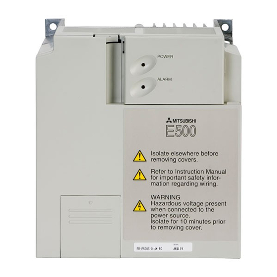
Page 12: Appearance And Structure
Connection RS485 or control unit POWER lamp (yellow) ALARM lamp (red) Inboard option mounting position Connector for connection of inboard option Control circuit terminal block SINK Control logic changing connector SOUR CE Main circuit terminal block Wiring cover MITSUBISHI ELECTRIC... -
Page 13: Wiring
Wiring Wiring Overview CAUTION: The terminals PC-SD of the 24V DC power supply must not be shorted. Otherwise the inverter will be damaged. Motor I> 3-phase main supply I> I> 24V DC Output Jumper must be removed if Reference point for control inputs a DC choke coil is connected! Start forward External brake resistor... -
Page 14: Wiring Of The Main Circuit
Please see the main frequency inverter manual for details on the required cable dimensions for your model. NOTE The inverter must be grounded using the dedicated ground terminal. 1-phase power supply 3-phase power supply FR-E 520S EC FR-E 540 EC Dedicated ground terminal MITSUBISHI ELECTRIC... - Page 15 Wiring NOTE It is recommended to use a shielded motor cable in order to reduce cable radiation. 1-phase 3-phase power supply power supply FR-E 520 S EC FR-E 540 EC − − The maximum wiring length of the motor cable Capacity Classes FR-E 500 0.4 k 0.75 k...
-
Page 16: Main Circuit Terminals
Wiring 4.2.2 Main Circuit Terminals Terminal assignment for 1-phase power supply − Screw size: M4 Screw tightening torque: 1.5Nm Terminal assignment for 3-phase power supply − Screw size: M4 Screw tightening torque: 1.5Nm MITSUBISHI ELECTRIC... -
Page 17: Wiring Of The Control Circuit
Wiring Wiring of the Control Circuit The following picture shows the arrangement of the terminal for the control circuit of the inverter: POW ER ALAR M SINK Jumper SOURC E Control logic The control signal level can be adjusted with the jumper. At the factory the jumper on the EC units is set to the “Source”... - Page 18 Frequency te. Switched high when be- detection low the detection frequency (*1). The maximum contact load is 24V DC / 0.1A. Reference potential for the Reference potential Signals RUN and FU for signal outputs MITSUBISHI ELECTRIC...
- Page 19 Wiring Signal Terminal Terminal name Description One of the following monito- ring functions can be selec- ted: output frequency, motor Factory setting current or motor voltage. of output item: E.g. a DC voltmeter can be output frequency connected. Analog output The max.
-
Page 20: Parameter
0 / 0.1–9998 Frequency at 5V (10V) input voltage 1–400Hz 50Hz Frequency at 20mA input current 1–400Hz 50Hz Up-to-frequency sensitivity 0–100% Setting of control out- Output frequency detection 0–400Hz puts Output frequency detection for reverse rotation 0–400Hz / 9999 9999 MITSUBISHI ELECTRIC... - Page 21 Parameter Func- Para- Meaning Setting range Default tion meter Second acceleration/deceleration time 0–360s / 0–3600s 5s / 10s 0–360s / 0–3600s / Second deceleration time 9999 9999 Second 0–30% / 9999 9999 functions Second torque boost Second V/F (base frequency) 0–400Hz / 9999 9999 Second stall prevention operation current...
- Page 22 0 / 1 Rated motor slip 0–50% / 9999 9999 functions Slip compensation response time 0.01–10s 0.5s Constant output region slip 0 / 9999 9999 compensation selection Stop 0–100s / selection Stop selection 1000–1100s / 9999 function 8888 / 9999 MITSUBISHI ELECTRIC...
- Page 23 Parameter Func- Para- Meaning Setting range Default tion meter Output phase failure protection selection 0 / 1 Analog polarity reversible lower limit 0–100% / 9999 9999 Operation command write 0 / 1 Additional functions Speed command write 0 / 1 Link start mode selection 0 / 1 E²PROM write selection...
-
Page 24: Error Messages And Remedies
O/Temp and halts inverter output. The cooling fan breaks down or Replace the cooling fan an operation different from the Fan breakdown setting of parameter 244 (coo- Failure ling fan operation selection) is performed. MITSUBISHI ELECTRIC... - Page 25 Error on access of the data me- Please contact your nearest mory of the inverter. MITSUBISHI ELECTRIC re- Corrupt Memory error Memry presentative if the error oc- curs again. A connection error between in-...
- Page 26 ON). you attempted to set any pa- rameter value while parame- ter write is being inhibited in Pr. 77 “parameter write inhi- bit selection” The stall prevention operation level (Pr. 22) is adjustable. It is factory-set to 150%. MITSUBISHI ELECTRIC...
-
Page 27: Dimensions Of The Frequency Inverters
Dimensions Dimensions Dimensions of the Frequency Inverters FR-E 520S-0.4 k bis 2.2 k EC and FR-E 540-0.4 k to 3.7 k EC Type FR-E 520S-0.4 k / 0.75 k EC FR-E 520S-1.5 k / 2.2 k EC FR-E 540-0.4 k / 0.75 k EC FR-E 540-1.5 k bis 3.7 k EC ø... - Page 28 NL-7051 HS Varsseveld e mail: sales.info@meir.mee.com Fax: +359 (0)2 / 97 44 061 Phone: +31 (0)315 / 257 260 ELEKTROSTYLE RUSSIA MITSUBISHI ELECTRIC . e mail: — Fax: +31 (0)315 / 257 269 ITALY ul. Garschina 11 EUROPE B.V e mail: —...