Sharp LC-32D62U Service Manual
Lcd color television
Hide thumbs
Also See for LC-32D62U:
- Operation manual (65 pages) ,
- Specifications (2 pages) ,
- Operation manual (60 pages)
Table of Contents
Advertisement
TopPage
[1]
SPECIFICATIONS ................................. . ....... 1-1
[1]
OPERATION MANUAL .......................... . ....... 2-1
[1]
DIMENSIONS ........................................ . ....... 3-1
[1]
REMOVING OF MAJOR PARTS ........... . ....... 4-1
CHAPTER 5. ADJUSTMENT
[1]
ADJUSTMENT PROCEDURE ............... . ....... 5-1
[1]
TROUBLE SHOOTING TABLE.............. . ....... 6-1
[1]
MAJOR IC INFORMATIONS.................. . ....... 7-1
[1]
OVERALL WIRING DIAGRAM (LC-
Parts marked with "
" are important for maintaining the safety of the set. Be sure to replace these parts with specified ones for maintaining the
safety and performance of the set.
SERVICE MANUAL
DRAFT
In the interests of user-safety (Required by safety regulations in some countries) the set should
be restored to its original condition and only parts identical to those specified should be used.
CONTENTS
LC-32D62U/LC-37D62U 1st
No. S17A9LC32D62U
LCD COLOR TELEVISION
LC-32D62U
LC-37D62U
32D62U) ........................................................8-1
[2]
37D62U) ........................................................8-3
[3]
SYSTEM BLOCK DIAGRAM .........................8-5
[4]
MAIN BLOCK DIAGRAM...............................8-7
[1]
MAIN Unit ......................................................9-1
[2]
TERMINAL Unit .............................................9-9
[3]
R/C, LED Unit ..............................................9-15
[4]
KEY Unit ......................................................9-16
[1]
DESCRIPTION OF SCHEMATIC DIA-
[2]
R/C, LED Unit ..............................................10-2
[3]
MAIN Unit ....................................................10-3
[4]
TERMINAL Unit .........................................10-49
[5]
KEY Unit ....................................................10-53
This document has been published to be used for
after sales service only.
The contents are subject to change without notice.
Advertisement
Table of Contents
Troubleshooting

Related Manuals for Sharp LC-32D62U


Summary of Contents for Sharp LC-32D62U
-
Page 1: Table Of Contents
TopPage LC-32D62U/LC-37D62U 1st SERVICE MANUAL No. S17A9LC32D62U LCD COLOR TELEVISION LC-32D62U LC-37D62U DRAFT In the interests of user-safety (Required by safety regulations in some countries) the set should be restored to its original condition and only parts identical to those specified should be used. -
Page 2: Safety Precaution Important Service Safety Pre- Caution
LC-32D62U/LC-37D62U 1st LC-32D62U/LC-37D62U 1st SAFETY PRECAUTION Service Manual IMPORTANT SERVICE SAFETY PRECAUTION Service work should be performed only by qualified service technicians who are thoroughly familiar with all safety checks and the servicing guidelines which follow: WARNING • Use an AC voltmeter having with 5000 ohm per volt, or higher, sen- sitivity or measure the AC voltage drop across the resistor. -
Page 3: Precautions A Prendre Lors De La Reparation
LC-32D62U/LC-37D62U 1st PRECAUTIONS A PRENDRE LORS DE LA REPARATION Ne peut effectuer la réparation qu' un technicien spécialisé qui s'est parfaitement accoutumé à toute vérification de sécurité et aux conseils suivants. AVERTISSEMENT • A l'aide de deux fils à pinces, brancher une résistance de 1.5 kΩ... -
Page 4: Precautions For Using Lead-Free Solder
LC-32D62U/LC-37D62U 1st PRECAUTIONS FOR USING LEAD-FREE SOLDER Employing lead-free solder • “PWBs” of this model employs lead-free solder. The LF symbol indicates lead-free solder, and is attached on the PWBs and service manuals. The alphabetical character following LF shows the type of lead-free solder. -
Page 5: Chapter 1. Specifications
The dimensional drawings are shown on the inside back cover. As part of policy of continuous improvement, SHARP reserves the right to make design and specification changes for product improvement without prior notice. The performance specification figures indicated are nominal values of production units. -
Page 6: Part Names
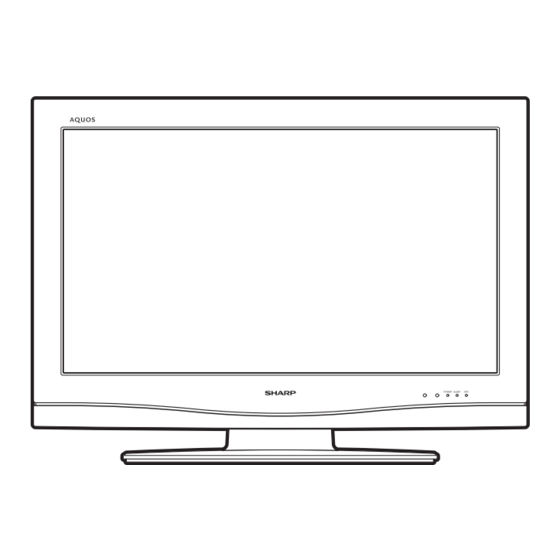
LC-32D62U/LC-37D62U 1st CHAPTER 2. LC-32D62U/LC-37D62U 1st OPERATION MANUAL Service Manual [1] OPERATION MANUAL Part names TV (Front) Remote control sensor OPC indicator* OPC sensor* SLEEP indicator** POWER indicator** TV (Rear) Channel buttons INPUT button HDMI terminal (INPUT 4) Volume POWER button... - Page 7 LC-32D62U/LC-37D62U 1st Part names TV POWER: Switch the TV power on or enters Remote control unit standby. DISPLAY: Display the channel information. SOURCE POWER: Turns the power of the external equipment on and off. External equipment operational buttons: Operate the external equipment.
-
Page 8: Removing The Stand
Setting the TV on the wall CAUTION This TV should be mounted on the wall only with the AN-37AG2 (SHARP) wall mount bracket. The use of other wall mount brackets may result in an unstable installation and may cause serious injuries. -
Page 9: Troubleshooting
LC-32D62U/LC-37D62U 1st Appendix Troubleshooting Problem Possible Solution • • No power Check if you pressed TV POWER on the remote control unit. If the indicator on the TV does not light up, press POWER on the TV. • Is the AC cord disconnected? •... -
Page 10: Connecting A Pc
LC-32D62U/LC-37D62U 1st Preparation Connecting a PC When connecting to a PC with an HDMI terminal. (INPUT 4 or 5) Example HDMI cable (commercially available) NOTE • The HDMI terminals only support digital signal. PC compatibility chart It is necessary to set the PC correctly to display XGA and WXGA signal. -
Page 11: Basic Adjustment Settings
LC-32D62U/LC-37D62U 1st Basic adjustment settings Menu items for TV/INPUT 1/2/3 Menu items for HDMI Picture Picture Backlight Backlight Contrast Contrast Brightness Brightness Color Color Tint Tint Sharpness Sharpness Advanced Advanced Color Temp. Color Temp. Black Black Monochrome 3D-Y/C Film Mode... -
Page 12: Chapter 3. Dimensions Dimensions
LC-32D62U/LC-37D62U 1st CHAPTER 3. LC-32D62U/LC-37D62U 1st DIMENSIONS Service Manual [1] DIMENSIONS Unit: Inch/(mm) LC-32D62U 797) (701.4) (507) (200) (88) (97) (273) LC-37D62U (919) (822.6) (540) (116) (97) (200) (292) 3 – 1... -
Page 13: Chapter 4. Removing Of Major Parts
2. Remove the 4 lock screws and detach the Stand Base Ass'y. 3. Remove the 9 lock screws, 3 lock screws and detach the Rear Cabinet. (LC-32D62U) Remove the 9 lock screws, 4 lock screws and detach the Rear Cabinet. (LC-37D62U) - Page 14 LC-32D62U/LC-37D62U 1st 4. Remove the 2 lock screws and detach the Stand Assist Angle. 5. Remove the 4 lock screws and detach the Center Angle-L and R. 6. Remove the 1 lock screw and detach the Stand Area Cover. 7. Remove the 4 lock screws and detach the Stand Fix Angle.
- Page 15 LC-32D62U/LC-37D62U 1st 9. Disconnect all the connectors from all the PWBs. 10.Remove the Top Cover Ass'y. Remove the 2 lock screws from the Top Cover Ass'y and detach the KEY Unit. Top Cover [KM] KEY Unit [CN5] (32D62U) [CN4] (32D62U)
- Page 16 LC-32D62U/LC-37D62U 1st 11.Remove the 4 lock screws and detach the Speaker-L and R. 12.Remove the 2 lock screws and detach the R/C, LED Unit. 13.Remove the 5 lock screws and detach the Tray Chassis. Tray Chassis Speaker-R Speaker-L R/C, LED Unit...
- Page 17 LC-32D62U/LC-37D62U 1st 14.Remove the 2 lock screws and detach the Jack Angle. 15.Remove the 6 lock screws and detach the POWER Unit. 16.Remove the 4 lock screws and detach the TERMINAL Unit. 17.Remove the 5 lock screws, 2 lock rivets and detach the MAIN PWB Radiator and MAIN Unit.
- Page 18 LC-32D62U/LC-37D62U 1st 18.Remove the 6 lock screws and detach the Rug Angle Top-L and R. (LC-32D62U) Remove the 4 lock screws and detach the Rug Angle Top-L and R. (LC-37D62U) 19.Remove the 6 lock screws and detach the Rug Angle Bottom-L and R.
- Page 19 LC-32D62U/LC-37D62U 1st CHAPTER 5. LC-32D62U/LC-37D62U 1st ADJUSTMENT Service Manual [1] ADJUSTMENT PROCEDURE The adjustment values are set to the optimum conditions at the factory before shipping. If a value should become improper or an adjustment is required due to part replacement, make an adjustment according to the following procedure.
- Page 20 LC-32D62U/LC-37D62U 1st 2. When the formatting is over, the following window appears. Click [OK]. 3. Click [Exit] to finish the formatting. NOTE: When you are done, take out the SD card once to make sure it is finished, and then insert it again.
- Page 21 LC-32D62U/LC-37D62U 1st 5. If any of the procedures fails, the following upgrade failure screen shows up. For the failing procedure, the “NG” marking turns red. NOTE: In such case, try to upgrade the software again. If it still fails, the hardware may be in trouble.
- Page 22 LC-32D62U/LC-37D62U 1st 4. A couple to dozen seconds after the set starts, the upgrade screen below shows up. The upgrade progress is indicated on screen. The power LED indicator goes out once and then starts flashing in green. (It takes 2-3 minutes to get the monitor microprocessor software upgraded.) 5.
- Page 23 LC-32D62U/LC-37D62U 1st 3. Entering and exiting the adjustment process mode 1) Before entering the adjustment process mode, the AV position RESET in the video adjustment menu. 2) While holding down the “VOL (–)” and “INPUT” keys at a time, plug in the AC cord of the main unit to turn on the power.
- Page 24 LC-32D62U/LC-37D62U 1st 5. List of adjustment process mode menu The character string in brackets [ ] will appear as a page title in the adjustment process menu header. Page Line Item Description Remarks (adjustment detail, etc.) [INFO] MAIN Version Main software version...
- Page 25 LC-32D62U/LC-37D62U 1st Page Line Item Description Remarks (adjustment detail, etc.) [FR DDRTEST] DDRA TEST1 DDRA TEST2 DDRB TEST1 DDRB TEST2 DDRB TEST3 [M GAMMA IN] MONITOR GAMMA IN 1 Standard value 1(WBI10184) Adjustment gradation setting. MONITOR GAMMA IN 2 Standard value 2(WBI20352)
- Page 26 LC-32D62U/LC-37D62U 1st Page Line Item Description Remarks (adjustment detail, etc.) [SOUND 3] PEQ1_F0 PEQ1_Q PEQ1_GAIN PEQ2_F0 PEQ2_Q PEQ2_GAIN PEQ3_F0 PEQ3_Q PEQ3_GAIN PEQ4_F0 PEQ4_Q PEQ4_GAIN [SOUND 4] PEQ5_F0 PEQ5_Q PEQ5_GAIN VIRTUALIZER_LEVEL BASS_BOOST_LEVEL SLICER_LEVEL HPF_SW HPF_LR LPF_SW SW_MIXING_LEVEL [M OPC1] BRIGHTNESS DA0...
- Page 27 LC-32D62U/LC-37D62U 1st Page Line Item Description Remarks (adjustment detail, etc.) [M ADL1] OPC33 ADLEVEL 0 OPC33 ADLEVEL 1 OPC33 ADLEVEL 2 OPC33 ADLEVEL 3 OPC33 ADLEVEL 4 OPC33 ADLEVEL 5 OPC33 ADLEVEL 6 OPC33 ADLEVEL 7 OPC33 ADLEVEL 8 OPC33 ADLEVEL 9...
- Page 28 LC-32D62U/LC-37D62U 1st Page Line Item Description Remarks (adjustment detail, etc.) [MEMORY CLR] KEY LOCK(1217) KOUTEI AREA ALL CLEAR A MODE AREA CLEAR BACKUP AREA CLEAR B MODE AREA CLEAR EXECUTION [ETC] EEP SAVE Writing setting values to EEPROM. EEP RECOVER Reading setting values from EEPROM.
-
Page 29: Adjustment Procedure
7. Video signal adjustment procedure 7.1. Signal adjustment 1. Checking the Device Before starting the adjustment, make sure the adjustment tool and signal generator are set for Sharp LCD US. Checking the signal generator level adjustment (Set to the standard level.) • Composite signal 0.714 Vp-p ±... - Page 30 LC-32D62U/LC-37D62U 1st 5. Component 33K signal adjustment Adjustment item Adjustment conditions Adjustment procedure Setting 1080i signal Feed the 100% color bar signal to VIDEO 1 COMPONENT input. 1080i 100% Color saturation 100% color bar 100% white 0% black Automatic adjust- Move the cursor to [ HDTV ADJ] and press the [ENTER] key.
- Page 31 (This is because the adjustment is made to achieve the same remainder of RGB setting / Point 5 4 at each point.) WBI50800 [Adjustment value] •As per the “standard set” submitted by Engineering Department MG5G**** MG5B**** “LC-32D62U/LC-37D62U” Teaching set MG5R**** [Adjustment reference] Instrument: Minolta CA-210 Engineering instrument Point 4 Level Reference Adj. spec Ins. spec ±0.0025...
- Page 32 LC-32D62U/LC-37D62U 1st 7.3. Adjusting procedure by use of [RS-232C] 1. Get ready the PC with COM port (RS-232C) running on Windows 95/98/ME/2000/XP operating system, as well as the RS-232C cross cable. 2. Start the unit with the RS-232C cable connected.
-
Page 33: Chapter 6. Trouble Shooting Table
LC-32D62U/LC-37D62U 1st CHAPTER 6. LC-32D62U/LC-37D62U 1st TROUBLE SHOOTING TABLE Service Manual [1] TROUBLE SHOOTING TABLE No video (1) COMPOSITE: No external input video COMPOSITE: No external input video [INPUT-1] [INPUT-2] Is INPUT-1 selected on the Select INPUT-1 on the input... - Page 34 LC-32D62U/LC-37D62U 1st No video (2) COMPONENT: No external input video COMPONENT: No external input video S-VIDEO: No external input video [INPUT-1] [INPUT-3] [INPUT-2] Is INPUT-1 selected on the input select Is INPUT-3 selected on the input select Is INPUT-2 selected on the input select menu...
- Page 35 LC-32D62U/LC-37D62U 1st No video (3) No video at UHF/VHF broadcast signal reception No video at digital broadcast signal reception Is the specified TV signal selected on the input select menu screen? Is there the analog video Check the tuner, IC8601...
- Page 36 LC-32D62U/LC-37D62U 1st [HDMI signal input] No video (4) No external input video [INPUT-4] Is INPUT-4 selected on the input select menu screen? Select INPUT-4 on the input select menu screen for the right input signal. Does the HOT PLUG detection function? Check the line between SC1501 and IC9101 (CPLD) (Q1506, Q1508, etc.).
- Page 37 LC-32D62U/LC-37D62U 1st [HDMI signal input] No video (4) No external input video [INPUT-5] Is INPUT-5 selected on the input select menu screen? Select INPUT-5 on the input select menu screen for the right input signal. Does the HOT PLUG detection function? Check the line between SC1502 and IC9101 (CPLD) (Q1505, Q1507, etc.).
- Page 38 LC-32D62U/LC-37D62U 1st No audio (1) [Audio signal] INPUT-1 No audio [Audio signal] INPUT-2 No audio [Audio signal] INPUT-3 No audio [INPUT-1 input] [INPUT-2 input] [INPUT-3 input] Is INPUT-1 selected on the input select menu Is INPUT-2 selected on the input select menu...
- Page 39 LC-32D62U/LC-37D62U 1st Is there the audio signal input at pins (5) (L) and (3) (R) of IC2701 (STEREO_AMP)? Check the line between P2704 and IC2701, and their peripheral circuits (AMP_MUTE line). Is the audio output from IC2701 as specified? Check IC2701 and its periph- eral circuits.
- Page 40 LC-32D62U/LC-37D62U 1st No Audio (1) [Audio signal] INPUT-5 No audio (HDMI analog input) [HDMI analog input] Is the audio output selected Is INPUT-5 selected on the for “VARIABLE” on the input select menu screen? menu screen? Set the audio output to “FIXED”...
- Page 41 LC-32D62U/LC-37D62U 1st [with HDMI connected] No audio (2) No audio in all modes (3) [Audio signal] INPUT-4 No audio (HDMI connected) [Audio signal] INPUT-5 No audio (HDMI connected) [INPUT-4 input] Is INPUT-4 selected Is the audio output selected for on the input select menu screen? “VARIABLE”...
- Page 42 LC-32D62U/LC-37D62U 1st No audio (4) No audio at digital broadcast signal reception No audio at UHF/VHF broadcast signal reception Move the sound volume key. Set the audio output to Is the audio output selected Set the audio output to Does the volume icon indi- “FIXED”.
- Page 43 LC-32D62U/LC-37D62U 1st No audio signal at DIGITAL AUDIO OUTPUT terminal (Analog sound heard) No INPUT-4/5 (HDMI) audio No audio at digital broadcast signal reception If no video appears, refer to Are there the IF_OUT_N Check the tuner (TU1101) “No external input video and IF_OUT_P signal out- and its peripheral circuits.
- Page 44 LC-32D62U/LC-37D62U 1st No monitor audio Is the audio output from the monitor set at “VARIABLE” or Check the bus line (SCL0_5/SDA0_5) and IC1404. Replace “FIXED” on the menu screen? as required. Are the audio signal outputs at pins (40) (L) and (41) (R) of Check IC1404 and its peripheral circuits.
- Page 45 LC-32D62U/LC-37D62U 1st LED flashing timing chart for error notification. 250ms 1sec 1) Power LED (The power LED (Green) which lights during TV reception flashes.) Error type Power green LED operation (1 cycle) Pins are microprocessor (IC2002) pins. Lamp failure ERR_PNL (pin 43): L failure. Confirmed after 10 consecutive...
- Page 46 LC-32D62U/LC-37D62U 1st Error type Notification LED operation (1 cycle) Pins are microprocessor pins unless otherwise specified. PANEL_POW DET_PNL_5V (pin 58) failure (L). Panel power is not applied. PNL_5V failure If error is detected during operation, error standby is activated H: On Flashes 5 times by polling.
-
Page 47: Chapter 7. Major Ic Informations
LC-32D62U/LC-37D62U 1st CHAPTER 7. LC-32D62U/LC-37D62U 1st MAJOR IC INFORMATIONS Service Manual [1] MAJOR IC INFORMATIONS 1. IC501 (MM3151XQ) This I2C bus-controlled video switch is designed to switch between tow-system color difference (component) signal, one-system S video signal and three-system composite signal. - Page 48 LC-32D62U/LC-37D62U 1st 11. IC8101 (RH-iXB281WJZZQ) This LSI with MPEG-2 system decoder performs back-end processing for digital broadcasting. It is equipped with a CPU (processor core: AM33-3), de scrambler (DES), transport stream de-multiplexer, video decoder (MPEG-2 MP@HL compatible), graphic processor, audio decoder (AC3 compat- ible), and an NTSC video encoder.
- Page 49 LC-32D62U/LC-37D62U 1st MEMO 7 – 3...
-
Page 50: Overall Wiring Diagram (Lc 32D62U)
LC-32D62U/LC-37D62U 1st CHAPTER 8. LC-32D62U/LC-37D62U 1st OVERALL WIRING/BLOCK DIAGRAM Service Manual [1] OVERALL WIRING DIAGRAM (LC-32D62U) 32" LCD Pan 1920×1080 KEY Unit D910 LCD Cont Unit CPWBX3520TPZ HDMI 1 HDMI 2 MAIN Unit E028 Optical HDMI Audio L/R Analog RF IN... - Page 51 LC-32D62U/LC-37D62U 1st 32" LCD Panel 1920×1080 LCD Cont Unit CPWBX3520TPZC INV-1 Unit RUNTKA283WJZZ POWER Unit RDENCA203WJQZ INV-2 Unit RUNTKA284WJZZ AC Socket (2pin) 8 – 2...
-
Page 52: Overall Wiring Diagram (Lc-37D62U)
LC-32D62U/LC-37D62U 1st [2] OVERALL WIRING DIAGRAM (LC-37D62U) 37" LCD Pan 1920×1080 KEY Unit D910 LCD Cont Uni CPWBX3520TP HDMI 1 MAIN Unit HDMI 2 E028 Optical HDMI Audio L/R Analog RF IN Digital Tuner TU1101 Card TERMINAL Unit D999 S-Video... - Page 53 LC-32D62U/LC-37D62U 1st 37" LCD Panel 1920×1080 LCD Cont Unit CPWBX3520TPZC INV-1 Unit RUNTKA275WJZZ POWER Unit RDENCA203WJQZ INV-2 Unit RUNTKA276WJZZ AC Socket (2pin) 8 – 4...
-
Page 54: System Block Diagram
LC-32D62U/LC-37D62U 1st [3] SYSTEM BLOCK DIAGRAM Connec Debugg Voice multiplex decoder Connector for Debugging Connector for CPLD writing Connector for writing Connector for software writing 8 – 5... - Page 55 LC-32D62U/LC-37D62U 1st Connector for Connector for software writing Debugging /emulator Connector for model type 8 – 6...
-
Page 56: Main Block Diagram
LC-32D62U/LC-37D62U 1st [4] MAIN BLOCK DIAGRAM D1308 D1308 D1307 1,14,6,10,15,12 16,17,18,23,13 C1.Y 21 CY1 D1304 C1.PLUG 38 SW1 COMP3 C1.PB 23 PB1 C1.PR 25 PR1 D1305 D1306 D1304 S3.C Q1307 S3.F 80 S2-3 DVP3.3V MUTE S3.Y IC1408 Q1308 NJM4565V MUTE BUFF.AMP. - Page 57 LC-32D62U/LC-37D62U 1st C1.Y 21 CY1 38 SW1 C1.PLUG COMP3 C1.PB 23 PB1 C1.PR 25 PR1 S3.C S3.F 80 S2-3 13:Vcc,77:Vcc S3.Y S-VIDEO2 POW_SW BUSY BUSY S3.PLUG 42 SW3 CNVss S3.V IXB986WJ VIDEO2 S3.PLUG C2.Y 27 CY2 C2.PLUG 40 SW2 C2.PB...
-
Page 58: Chapter 9. Printed Wiring Board Assemblies
LC-32D62U/LC-37D62U 1st CHAPTER 9. LC-32D62U/LC-37D62U 1st PRINTED WIRING BOARD ASSEMBLIES Service Manual [1] MAIN Unit MAIN Unit (Side-A) 9 – 1... - Page 59 LC-32D62U/LC-37D62U 1st 9 – 2...
- Page 60 LC-32D62U/LC-37D62U 1st P2601 P9002 P2603 P2602 R2611 R2612 C9601 R9623 FB2609 C9604 R9627 R3515 R9611 R9612 R3522 C9613 Q9607 C9603 C2601 IC9603 L9602 R9617 MAIN Unit IC3501 FB3501 R9649 C9602 R9614 C3501 (Side-A Chip) R9621 R3538 R3531 C9621 C3429 C9652...
- Page 61 LC-32D62U/LC-37D62U 1st R9008 C1301 R1310 P1401 R1347 LUG1102 R1172 P2603 P9701 P9702 R1174 R1173 R2611 R2613 IC1301 R2612 C9701 FDC1 C9703 C9702 FB1301 R1319 R9624 R1316 FB9702 R1321 R1324 L9602 R1350 R1320 R1323 C1306 C9609 C1309 R1407 C9619 C9615 L9601...
- Page 62 LC-32D62U/LC-37D62U 1st MAIN Unit (Side-B) 9 – 5...
- Page 63 LC-32D62U/LC-37D62U 1st 9 – 6...
- Page 64 LC-32D62U/LC-37D62U 1st TL1404 TL1406 TL1407 TL9704 TL2619 TL9714 TL9719 TL1405 TL1403 TL9713 R1351 R1303 R9707 Q1301 R9708 TL9712 TL9703 TL9711 TL9708 TL9716 TL9705 R1306 Q1303 TL9706 FL9703 TL9702 TL1320 R1326 TL9715 TL9717 TL9718 TL9710 TL9707 FL9702 R1307 FB9710 FB9709 FB9711...
- Page 65 LC-32D62U/LC-37D62U 1st TP2603 TL2636 R2620 C2605 TL2633 FL2614 FB2603 TL2602 TP2601 TL2610 TL2609 IC9003 IC2601 R2619 TL2632 TL2628 TL2623 TP2602 TP2604 D9003 R2628 TL2650 TL2637 TL2638 TL2603 TL2649 TL2622 TL2601 TL2621 TL9004 R2618 TL9017 TL9045 TL9015 R2603 TL2651 R2616 TP2606...
-
Page 66: Terminal Unit
LC-32D62U/LC-37D62U 1st [2] TERMINAL Unit TERMINAL Unit (Side-A) 9 – 9... - Page 67 LC-32D62U/LC-37D62U 1st 9 – 10...
- Page 68 LC-32D62U/LC-37D62U 1st TERMINAL Unit (Side-A Chip) IC502 SC502 SC501 C531 FB525 FB526 C591 R663 R665 C595 R586 R664 FB502 C599 C590 C589 C2749 R27 R600 C584 R562 C600 R598 R599 C587 IC504 R597 C554 C598 R606 IC503 R571 C552 R577...
- Page 69 LC-32D62U/LC-37D62U 1st D2703 R2724 LUG2702 C2718 P2704 C2749 R2725 R2719 C554 FB2704 C2708 L2703 R2706 C2745 R2711 C2706 L2702 C546 C2723 C2751 C2709 C2707 C2729 C2724 IC2701 R2726 R2716 C2725 C547 C2748 C2710 C2711 C2728 C2726 C2736 C2727 C2716 C2715...
- Page 70 LC-32D62U/LC-37D62U 1st TERMINAL Unit (Side-B) 9 – 13...
- Page 71 LC-32D62U/LC-37D62U 1st 9 – 14...
-
Page 72: R/C, Led Unit
LC-32D62U/LC-37D62U 1st [3] R/C, LED Unit R/C, LED Unit (Side-A) R/C, LED Unit (Side-A Chip) R101 C105 R136 R102 R110 R105 R137 R108 Q103 R109 Q102 R106 R104 R107 R123 D113 R111 R124 R112 R114 R127 R113 9 – 15... -
Page 73: Key Unit
LC-32D62U/LC-37D62U 1st [4] KEY Unit KEY Unit (Side-A) KEY Unit (Side-A Chip) S157 P151 S153 S151 D151 R151 S152 S154 D152 R153 S155 9 – 16... -
Page 74: Chapter 10. Schematic Diagram
LC-32D62U/LC-37D62U 1st CHAPTER 10. LC-32D62U/LC-37D62U 1st SCHEMATIC DIAGRAM Service Manual [1] DESCRIPTION OF SCHEMATIC DIAGRAM 1. VOLTAGE MEASUREMENT CONDITION: 1) The voltages at test points are measured on exclusive AC adaptor and the stable supply voltage of AC 120V. Signals are fed by a color bar signal generator for servicing purpose and the above voltages are measured with a 20k ohm/V tester. -
Page 75: R/C, Led Unit
LC-32D62U/LC-37D62U 1st [2] R/C, LED Unit 10 – 2... -
Page 76: Main Unit
LC-32D62U/LC-37D62U 1st [3] MAIN Unit • MAIN Unit-1/23 10 – 3... - Page 77 LC-32D62U/LC-37D62U 1st 10 – 4...
- Page 78 LC-32D62U/LC-37D62U 1st • MAIN Unit-2/23 10 – 5...
- Page 79 LC-32D62U/LC-37D62U 1st 10 – 6...
- Page 80 LC-32D62U/LC-37D62U 1st • MAIN Unit-3/23 10 – 7...
- Page 81 LC-32D62U/LC-37D62U 1st 10 – 8...
- Page 82 LC-32D62U/LC-37D62U 1st • MAIN Unit-4/23 10 – 9...
- Page 83 LC-32D62U/LC-37D62U 1st 10 – 10...
- Page 84 LC-32D62U/LC-37D62U 1st • MAIN Unit-5/23 10 – 11...
- Page 85 LC-32D62U/LC-37D62U 1st 10 – 12...
- Page 86 LC-32D62U/LC-37D62U 1st • MAIN Unit-6/23 10 – 13...
- Page 87 LC-32D62U/LC-37D62U 1st 10 – 14...
- Page 88 LC-32D62U/LC-37D62U 1st • MAIN Unit-7/23 10 – 15...
- Page 89 LC-32D62U/LC-37D62U 1st 10 – 16...
- Page 90 LC-32D62U/LC-37D62U 1st • MAIN Unit-8/23 10 – 17...
- Page 91 LC-32D62U/LC-37D62U 1st 10 – 18...
- Page 92 LC-32D62U/LC-37D62U 1st • MAIN Unit-9/23 10 – 19...
- Page 93 LC-32D62U/LC-37D62U 1st 10 – 20...
- Page 94 LC-32D62U/LC-37D62U 1st • MAIN Unit-10/23 10 – 21...
- Page 95 LC-32D62U/LC-37D62U 1st 10 – 22...
- Page 96 LC-32D62U/LC-37D62U 1st • MAIN Unit-11/23 All capacitor of this page is 25V, unless otherwise noted. 10 – 23...
- Page 97 LC-32D62U/LC-37D62U 1st 10 – 24...
- Page 98 LC-32D62U/LC-37D62U 1st • MAIN Unit-12/23 10 – 25...
- Page 99 LC-32D62U/LC-37D62U 1st 10 – 26...
- Page 100 LC-32D62U/LC-37D62U 1st • MAIN Unit-13/23 10 – 27...
- Page 101 LC-32D62U/LC-37D62U 1st 10 – 28...
- Page 102 LC-32D62U/LC-37D62U 1st • MAIN Unit-14/23 10 – 29...
- Page 103 LC-32D62U/LC-37D62U 1st 10 – 30...
- Page 104 LC-32D62U/LC-37D62U 1st • MAIN Unit-15/23 All capacitor of this page is 10V, unless otherwise noted. 10 – 31...
- Page 105 LC-32D62U/LC-37D62U 1st 10 – 32...
- Page 106 LC-32D62U/LC-37D62U 1st • MAIN Unit-16/23 10 – 33...
- Page 107 LC-32D62U/LC-37D62U 1st 10 – 34...
- Page 108 LC-32D62U/LC-37D62U 1st • MAIN Unit-17/23 10 – 35...
- Page 109 LC-32D62U/LC-37D62U 1st 10 – 36...
- Page 110 LC-32D62U/LC-37D62U 1st • MAIN Unit-18/23 10 – 37...
- Page 111 LC-32D62U/LC-37D62U 1st 10 – 38...
- Page 112 LC-32D62U/LC-37D62U 1st • MAIN Unit-19/23 10 – 39...
- Page 113 LC-32D62U/LC-37D62U 1st 10 – 40...
- Page 114 LC-32D62U/LC-37D62U 1st • MAIN Unit-20/23 10 – 41...
- Page 115 LC-32D62U/LC-37D62U 1st 10 – 42...
- Page 116 LC-32D62U/LC-37D62U 1st • MAIN Unit-21/23 10 – 43...
- Page 117 LC-32D62U/LC-37D62U 1st 10 – 44...
- Page 118 LC-32D62U/LC-37D62U 1st • MAIN Unit-22/23 10 – 45...
- Page 119 LC-32D62U/LC-37D62U 1st 10 – 46...
- Page 120 LC-32D62U/LC-37D62U 1st • MAIN Unit-23/23 10 – 47...
- Page 121 LC-32D62U/LC-37D62U 1st 10 – 48...
-
Page 122: Terminal Unit
LC-32D62U/LC-37D62U 1st [4] TERMINAL Unit • TERMINAL Unit-1/2 10 – 49... - Page 123 LC-32D62U/LC-37D62U 1st 10 – 50...
- Page 124 LC-32D62U/LC-37D62U 1st • TERMINAL Unit-2/2 10 – 51...
- Page 125 LC-32D62U/LC-37D62U 1st 10 – 52...
-
Page 126: Key Unit
LC-32D62U/LC-37D62U 1st [5] KEY Unit 10 – 53... -
Page 127: Parts Guide
LC-32D62U/LC-37D62U 1st PartsGuide PARTS GUIDE No. S17A9LC32D62U LC-32D62U Note: The reference numbers on the PWB LC-37D62U are arranged in alphabetical order. MODELS CONTENTS PRINTED WIRING BOARD DUNTKE028FM06 (MAIN Unit) ASSEMBLIES (NOT REPLACEMENT ITEM) CABINET AND MECHANICAL PARTS (LC-32D62U) PRINTED WIRING BOARD... - Page 128 LC-32D62U/LC-37D62U 1st PRICE PARTS CODE PART DESCRIPTION RANK MARK DELIVERY [1] PRINTED WIRING BOARD ASSEMBLIES (NOT REPLACEMENT ITEM) R/C, LED Unit DUNTKD909FM02 KEY Unit DUNTKD910FM02 TERMINAL Unit DUNTKD999FM07 [2] PRINTED WIRING BOARD ASSEMBLY MAIN Unit DUNTKE028FM06 RDENCA203WJQZ POWER Unit LCD CONTROL Unit...
- Page 129 LC-32D62U/LC-37D62U 1st PRICE PARTS CODE PART DESCRIPTION RANK MARK DELIVERY [6] DUNTKD999FM07 (TERMINAL Unit) C526 Capacitor, 0.1 25V Ceramic VCKYCY1EF104ZY C527 Capacitor, 0.1 25V Ceramic VCKYCY1EF104ZY C528 Capacitor, 22 16V Electrolytic VCERML1CN226MY C529 Capacitor, 0.1 25V Ceramic VCKYCY1EF104ZY C530 Capacitor, 0.1 25V Ceramic...
- Page 130 LC-32D62U/LC-37D62U 1st PRICE PARTS CODE PART DESCRIPTION RANK MARK DELIVERY [6] DUNTKD999FM07 (TERMINAL Unit) C2739 Capacitor, 0.1 50V Ceramic VCKYCY1HB104KY C2740 Capacitor, 0.1 50V Ceramic VCKYCY1HB104KY C2741 Capacitor, 150p 50V Ceramic VCCCCY1HH151JY C2742 Capacitor, 150p 50V Ceramic VCCCCY1HH151JY C2744 Capacitor, 10 25V Electrolytic...
- Page 131 LC-32D62U/LC-37D62U 1st PRICE PARTS CODE PART DESCRIPTION RANK MARK DELIVERY [6] DUNTKD999FM07 (TERMINAL Unit) Q510 Transistor, 2SC2735JC21TL VS2SC2735//-1Y Q511 Transistor, 2SC2735JC21TL VS2SC2735//-1Y Q512 Transistor, 2SC2735JC21TL VS2SC2735//-1Y Q516 Transistor, 2SC2735JC21TL VS2SC2735//-1Y Q518 Transistor, 2SC2735JC21TL VS2SC2735//-1Y Q520 VS2SC2735//-1Y Transistor, 2SC2735JC21TL R501 Resistor, 75 1/8W Metal Oxide...
- Page 132 LC-32D62U/LC-37D62U 1st PRICE PARTS CODE PART DESCRIPTION RANK MARK DELIVERY [6] DUNTKD999FM07 (TERMINAL Unit) R597 Resistor, 100 1/16W Metal Oxide VRS-CY1JF101JY R598 Resistor, 100 1/16W Metal Oxide VRS-CY1JF101JY R599 Resistor, 100 1/16W Metal Oxide VRS-CY1JF101JY R600 Resistor, 100 1/16W Metal Oxide...
- Page 133 LC-32D62U/LC-37D62U 1st PRICE PARTS CODE PART DESCRIPTION RANK MARK DELIVERY [7] DUNTKE028FM06 (MAIN Unit) C1308 Capacitor, 0.1 25V Ceramic VCKYCZ1EF104ZY C1309 Capacitor, 10 25V Ceramic RC-KZA383WJZZY C1313 Capacitor, 10 16V Ceramic RC-KZA510WJPZY C1314 Capacitor, 0.1 25V Ceramic VCKYCZ1EF104ZY C1315 Capacitor, 10 16V Ceramic...
- Page 134 LC-32D62U/LC-37D62U 1st PRICE PARTS CODE PART DESCRIPTION RANK MARK DELIVERY [7] DUNTKE028FM06 (MAIN Unit) C1543 Capacitor, 0.1 25V Ceramic VCKYCZ1EF104ZY C1544 Capacitor, 1000p 50V Ceramic VCKYCZ1HB102KY C1545 Capacitor, 0.1 25V Ceramic VCKYCZ1EF104ZY C1546 Capacitor, 1000p 50V Ceramic VCKYCZ1HB102KY C1547 Capacitor, 0.1 25V Ceramic...
- Page 135 LC-32D62U/LC-37D62U 1st PRICE PARTS CODE PART DESCRIPTION RANK MARK DELIVERY [7] DUNTKE028FM06 (MAIN Unit) C1632 Capacitor, 1000p 50V Ceramic VCKYCZ1HB102KY C1633 Capacitor, 10 16V Ceramic RC-KZA510WJPZY C1634 Capacitor, 10 16V Ceramic RC-KZA510WJPZY C1635 Capacitor, 0.1 25V Ceramic VCKYCZ1EF104ZY C1636 Capacitor, 100 6.3V Electrolytic...
- Page 136 LC-32D62U/LC-37D62U 1st PRICE PARTS CODE PART DESCRIPTION RANK MARK DELIVERY [7] DUNTKE028FM06 (MAIN Unit) C3340 Capacitor, 1000p 50V Ceramic VCKYCZ1HB102KY C3341 Capacitor, 0.1 10V Ceramic VCKYCZ1AB104KY C3342 Capacitor, 1000p 50V Ceramic VCKYCZ1HB102KY C3343 Capacitor, 0.1 10V Ceramic VCKYCZ1AB104KY C3344 Capacitor, 10 16V Ceramic...
- Page 137 LC-32D62U/LC-37D62U 1st PRICE PARTS CODE PART DESCRIPTION RANK MARK DELIVERY [7] DUNTKE028FM06 (MAIN Unit) C3428 Capacitor, 0.1 10V Ceramic VCKYCZ1AB104KY C3429 Capacitor, 100 6.3V Electrolytic VCAAPE0JJ107MY C3430 Capacitor, 100 6.3V Electrolytic VCAAPE0JJ107MY C3432 Capacitor, 0.01 25V Ceramic VCKYCZ1EB103KY C3501 Capacitor, 100 6.3V Electrolytic...
- Page 138 LC-32D62U/LC-37D62U 1st PRICE PARTS CODE PART DESCRIPTION RANK MARK DELIVERY [7] DUNTKE028FM06 (MAIN Unit) C8302 Capacitor, 0.1 25V Ceramic VCKYCZ1EF104ZY C8303 Capacitor, 0.1 25V Ceramic VCKYCZ1EF104ZY C8304 Capacitor, 0.1 25V Ceramic VCKYCZ1EF104ZY C8305 Capacitor, 0.1 25V Ceramic VCKYCZ1EF104ZY C8306 Capacitor, 0.1 25V Ceramic...
- Page 139 LC-32D62U/LC-37D62U 1st PRICE PARTS CODE PART DESCRIPTION RANK MARK DELIVERY [7] DUNTKE028FM06 (MAIN Unit) C8619 Capacitor, 0.1 10V Ceramic VCKYCZ1AB104KY C8620 Capacitor, 56p 50V Ceramic VCCCCZ1HH560JY C8621 Capacitor, 56p 50V Ceramic VCCCCZ1HH560JY C8622 Capacitor, 0.1 10V Ceramic VCKYCZ1AB104KY C8623 Capacitor, 0.1 10V Ceramic...
- Page 140 LC-32D62U/LC-37D62U 1st PRICE PARTS CODE PART DESCRIPTION RANK MARK DELIVERY [7] DUNTKE028FM06 (MAIN Unit) C9602 Capacitor, 0.1 10V Ceramic VCKYCZ1AB104KY C9603 Capacitor, 2200p 50V Ceramic VCKYCZ1HB222KY C9604 Capacitor, 220p 50V Ceramic VCKYCZ1HB221KY C9605 Capacitor, 2700p 50V Ceramic VCKYCZ1HB272KY C9606 Capacitor, 0.1 25V Ceramic...
- Page 141 LC-32D62U/LC-37D62U 1st PRICE PARTS CODE PART DESCRIPTION RANK MARK DELIVERY [7] DUNTKE028FM06 (MAIN Unit) D9008 Zener Diode, 3.6V RH-EX1234CEZZY D9601 Diode, MA2J11100L VHDMA111+++-1Y D9602 Zener Diode, 2.4V RH-EX1226CEZZY D9603 Diode, D1FH3 VHDD1FH3+++-1Y D9604 Diode, DG1M3-5063R VHDDG1M3+++-1Y D9605 RH-EX0256TAZZY Zener Diode...
- Page 142 LC-32D62U/LC-37D62U 1st PRICE PARTS CODE PART DESCRIPTION RANK MARK DELIVERY [7] DUNTKE028FM06 (MAIN Unit) IC1401 IC, AN5832SA-E1V VHIAN5832SA-1Y IC1403 IC, 24LC256-I/SN-G-GW1007T RH-IXB991WJQZY IC1404 IC, AK4683EQ VHIAK4683EQ-1Q IC1407 IC, TAS3108DCPR VHITAS3108D-1Y IC1408 IC, NJM4565V-TE1 VHINJM4565V-1Y IC1501 RH-IXC037WJQZS IC, BQC (HDMI EDID)
- Page 143 LC-32D62U/LC-37D62U 1st PRICE PARTS CODE PART DESCRIPTION RANK MARK DELIVERY [7] DUNTKE028FM06 (MAIN Unit) L8603 Coil, Peaking 0.33µH VPMKMR33JR50VY L8604 Coil, Peaking 0.68µH VPMKMR68JR84VY L8605 Coil, Peaking 0.68µH VPMKMR68JR84VY L8606 Coil, Peaking 0.22µH VPMKMR22JR37VY L8607 Coil, Peaking 0.22µH VPMKMR22JR37VY L8608 VPMKMR33JR50VY Coil, Peaking 0.33µH...
- Page 144 LC-32D62U/LC-37D62U 1st PRICE PARTS CODE PART DESCRIPTION RANK MARK DELIVERY [7] DUNTKE028FM06 (MAIN Unit) R1118 Resistor, 0 1/10W Metal Oxide VRS-TV1JD000JY R1119 Resistor, 0 1/10W Metal Oxide VRS-TV1JD000JY R1120 Resistor, 0 1/10W Metal Oxide VRS-TV1JD000JY R1121 Resistor, 0 1/10W Metal Oxide...
- Page 145 LC-32D62U/LC-37D62U 1st PRICE PARTS CODE PART DESCRIPTION RANK MARK DELIVERY [7] DUNTKE028FM06 (MAIN Unit) R1442 Resistor, 47k 1/16W Metal Oxide VRS-CZ1JF473FY R1443 Resistor, 47k 1/16W Metal Oxide VRS-CZ1JF473FY R1445 Resistor, 22 x2 1/16W Metal Oxide VRS-CJ1JF220JY R1446 Resistor, 4.7 1/16W Metal Oxide...
- Page 146 LC-32D62U/LC-37D62U 1st PRICE PARTS CODE PART DESCRIPTION RANK MARK DELIVERY [7] DUNTKE028FM06 (MAIN Unit) R1612 Resistor, 1M 1/16W Metal Oxide VRS-CZ1JF105JY R1614 Resistor, 4.7k 1/16W Metal Oxide VRS-CZ1JF472JY R1615 Resistor, 22k 1/16W Metal Oxide VRS-CZ1JF223FY R1616 Resistor, 10 1/16W Metal Oxide...
- Page 147 LC-32D62U/LC-37D62U 1st PRICE PARTS CODE PART DESCRIPTION RANK MARK DELIVERY [7] DUNTKE028FM06 (MAIN Unit) R2101 Resistor, 1k 1/16W Metal Oxide VRS-CZ1JF102FY R2103 Resistor, 1k 1/16W Metal Oxide VRS-CZ1JF102FY R2105 Resistor, 1k 1/16W Metal Oxide VRS-CZ1JF102FY R2107 Resistor, 10k 1/16W Metal Oxide...
- Page 148 LC-32D62U/LC-37D62U 1st PRICE PARTS CODE PART DESCRIPTION RANK MARK DELIVERY [7] DUNTKE028FM06 (MAIN Unit) R3332 Resistor, 22 1/16W Metal Oxide VRS-CZ1JF220JY R3333 Resistor, 22 1/16W Metal Oxide VRS-CZ1JF220JY R3334 Resistor, 22 1/16W Metal Oxide VRS-CZ1JF220JY R3335 Resistor, 22 1/16W Metal Oxide...
- Page 149 LC-32D62U/LC-37D62U 1st PRICE PARTS CODE PART DESCRIPTION RANK MARK DELIVERY [7] DUNTKE028FM06 (MAIN Unit) R3575 Resistor, 33 1/16W Metal Oxide VRS-CZ1JF330JY R3576 Resistor, 33 1/16W Metal Oxide VRS-CZ1JF330JY R3577 Resistor, 33 1/16W Metal Oxide VRS-CZ1JF330JY R8101 Resistor, 3.9k x8 1/16W Metal Composition...
- Page 150 LC-32D62U/LC-37D62U 1st PRICE PARTS CODE PART DESCRIPTION RANK MARK DELIVERY [7] DUNTKE028FM06 (MAIN Unit) R8185 Resistor, 0 1/16W Metal Oxide VRS-CZ1JF000JY R8186 Resistor, 47 1/16W Metal Oxide VRS-CZ1JF470JY R8187 Resistor, 47 1/16W Metal Oxide VRS-CZ1JF470JY R8188 Resistor, 10k 1/16W Metal Oxide...
- Page 151 LC-32D62U/LC-37D62U 1st PRICE PARTS CODE PART DESCRIPTION RANK MARK DELIVERY [7] DUNTKE028FM06 (MAIN Unit) R8391 Resistor, 150 1/16W Metal Oxide VRS-CZ1JF151JY R8392 Resistor, 22 1/16W Metal Oxide VRS-CZ1JF220JY R8393 Resistor, 22 1/16W Metal Oxide VRS-CZ1JF220JY R8394 Resistor, 22 1/16W Metal Oxide...
- Page 152 LC-32D62U/LC-37D62U 1st PRICE PARTS CODE PART DESCRIPTION RANK MARK DELIVERY [7] DUNTKE028FM06 (MAIN Unit) R8726 Resistor, 10k 1/16W Metal Oxide VRS-CZ1JF103FY R8727 Resistor, 100 1/16W Metal Oxide VRS-CZ1JF101FY R8728 Resistor, 100 1/16W Metal Oxide VRS-CZ1JF101FY R8801 Resistor, 47 1/16W Metal Oxide...
- Page 153 LC-32D62U/LC-37D62U 1st PRICE PARTS CODE PART DESCRIPTION RANK MARK DELIVERY [7] DUNTKE028FM06 (MAIN Unit) R9616 Resistor, 10k 1/16W Metal Oxide VRS-CZ1JF103FY R9617 Resistor, 10k 1/16W Metal Oxide VRS-CZ1JF103FY R9619 Resistor, 15k 1/16W Metal Oxide VRS-CZ1JF153FY R9621 Resistor, 27k 1/16W Metal Oxide...
- Page 154 LC-32D62U/LC-37D62U 1st [8] CABINET AND MECHANICAL PARTS (LC-32D62U) KEY Unit 1-11 1-11 R/C, LED Unit 1-10 POWER Unit MAIN Unit 54-1 TERMINAL Unit 54-3 54-2 54-4 54-3 54-5 54-4 54-3 54-3...
- Page 155 LC-32D62U/LC-37D62U 1st PRICE PARTS CODE PART DESCRIPTION RANK MARK DELIVERY [8] CABINET AND MECHANICAL PARTS (LC-32D62U) Front Cabinet Ass'y CCABAB691WJ02 Front Cabinet Not Available LED Cover GCOVAB821WJSA Front Cover GCOVAC045WJKA Badge, SHARP Not Available Shaine Trim HDECSA008WJSB SP-Net HPNLSA122WJSA Spacer, x2...
- Page 156 LC-32D62U/LC-37D62U 1st PRICE PARTS CODE PART DESCRIPTION RANK MARK DELIVERY [8] CABINET AND MECHANICAL PARTS (LC-32D62U) 54-2 Base Angle LANGKA956WJZZ 54-3 Leg Cushion-A, x4 PSPAZA949WJZZ 54-4 Leg Cushion-B, x2 PSPAZA950WJZZ 54-5 Screw (for COVER/ANG), x6 XEBS940P10000...
- Page 157 LC-32D62U/LC-37D62U 1st [9] CABINET AND MECHANICAL PARTS (LC-37D62U) KEY Unit 1-11 1-11 R/C, LED Unit 1-10 POWER Unit MAIN Unit 54-1 TERMINAL Unit 54-3 54-2 54-4 54-3 54-5 54-4 54-3 54-3...
- Page 158 LC-32D62U/LC-37D62U 1st PRICE PARTS CODE PART DESCRIPTION RANK MARK DELIVERY [9] CABINET AND MECHANICAL PARTS (LC-37D62U) Front Cabinet Ass'y CCABAB690WJ02 Front Cabinet Not Available LED Cover GCOVAB821WJSA Front Cover GCOVAC044WJKA Badge, SHARP Not Available Shaine Trim HDECSA007WJSB SP-Net HPNLSA123WJSA Spacer, x2...
- Page 159 LC-32D62U/LC-37D62U 1st PRICE PARTS CODE PART DESCRIPTION RANK MARK DELIVERY [9] CABINET AND MECHANICAL PARTS (LC-37D62U) 54-2 Base Angle LANGKA955WJZZ 54-3 Leg Cushion-A, x4 PSPAZA949WJZZ 54-4 Leg Cushion-B, x2 PSPAZA950WJZZ 54-5 Screw (for COVER/ANG), x6 XEBS940P10000 Wire Holder, x2 LHLDWA139WJKZ...
- Page 160 LC-32D62U/LC-37D62U 1st [11] PACKING PARTS (NOT REPLACEMENT ITEM)
- Page 161 LC-32D62U/LC-37D62U 1st PRICE PARTS CODE PART DESCRIPTION RANK MARK DELIVERY [11] PACKING PARTS (NOT REPLACEMENT ITEM) Packing Case [LC32D62U] SPAKCD303WJZZ Packing Case [LC37D62U] SPAKCD302WJZZ Stand Case [LC32D62U] SPAKFB167WJZZ Stand Case [LC37D62U] SPAKFB165WJZZ Stand Pad [LC32D62U] SPAKFB168WJZZ Stand Pad [LC37D62U] SPAKFB166WJZZ...
- Page 162 LC-32D62U/LC-37D62U 1st COPYRIGHT 2007 BY SHARP CORPORATION ALL RIGHTS RESERVED. No part of this publication may be reproduced, stored in a retrieval system, or transmitted in any form or by any means, electronic, mechanical, photocopying, recording, or otherwise, without prior written permission of the publisher.