Motorola MC3000 Operating And Installation Manual
Digital deskjet
Hide thumbs
Also See for MC3000:
- User manual (146 pages) ,
- User manual (152 pages) ,
- Quick start manual (2 pages)

Related Manuals for Motorola MC3000


Summary of Contents for Motorola MC3000
- Page 1 MC3000™ Digital Deskset L3223 Operator and Installation Manual 6880309L15-A 21 June 2002...
- Page 2 Motorola, at its option, will either repair or replace the product or refund the purchase price thereof, MC3000™ is a trademark of Motorola. and such action on the part of Motorola shall be the full Microsoft, Windows, and Windows NT are registered extent of Motorola’s liability hereunder.
-
Page 3: Table Of Contents
Programing Multiple Digital Desksets for Takeover Privileges 2-13 Configuring and Testing Deskset Functions 2-14 Tests 2-14 1) Buttons 2-15 2) LED / LCD Display Test 2-15 3) Data Test 2-15 4) Busy Test 2-16 MC3000 Digital Deskset Operator and Installation Manual (6880309L15-A) - Page 4 Initiating or Answering a Radio Channel Transmission 3-18 Initiating or Answering an Intercom Transmission 3-20 Adjusting the Volume 3-20 Adjusting the LCD Display Contrast 3-21 Chapter 4 Troubleshooting, Circuit Board and Schematics Introduction Troubleshooting Circuit Board Layout Schematics MC3000 Digital Deskset Operator and Installation Manual (6880309L15-A)
- Page 5 Contents Appendix A The “Labels” Program About the Labels Program Starting the Labels Program Help Feature Toolbar Creating a New Label File Adding and/or Editing Label Text Producing Labels Glossary Glossary-1 MC3000 Digital Deskset Operator and Installation Manual (6880309L15-A)
- Page 6 Contents MC3000 Digital Deskset Operator and Installation Manual (6880309L15-A)
-
Page 7: Introduction To This Manual
Introduction to this Manual About this Manual The purpose of this manual is to help you install and operate the MC3000 Digital Deskset. It is written for operators and for the technicians who are responsible for installing and troubleshooting the MC3000 Digital Deskset and related equipment. It provides reference information for technicians and Motorola field support engineers and technicians. - Page 8 (or L3239 for LTR radio). The maximum aggregate cable length between desksets and the master Digital Junction Box is 5000 ft. The MC3000 Deskset operates on +12 VDC using an external in-line 120 - 240 V 50/60 Hz power supply.
-
Page 9: Model Information
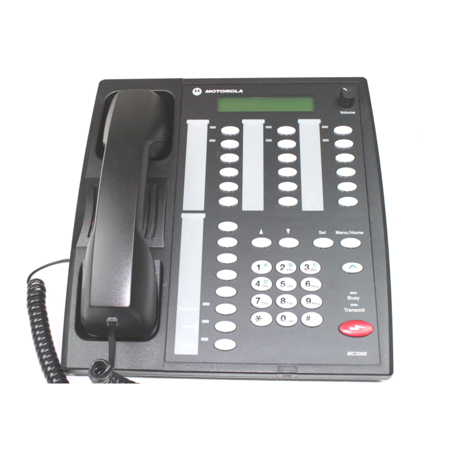
Introduction to this Manual Model Information Model Information TWO LINE x 20 Volume Menu/Home Busy Takeover Transmit Speaker Intercom MC3000 Figure 1-1: MC3000 Digital Deskset MC3000 Digital Deskset Operator and Installation Manual (6880309L15-A) -
Page 10: Mc3000 Digital Deskset Specifications
80mV nominal, auto leveled, - 10 dB to Receive Audio Input + 6dB nominal (with autolevel) 0.78 V or 80mV nominal into 600Ω Transmit Audio Output 31 in parallel Max. Number of consoles MC3000 Digital Deskset Operator and Installation Manual (6880309L15-A) -
Page 11: Mc3000 Accessories And Replacement Items
Failure to comply with these precautions or with specific warnings elsewhere in this manual violates safety standards of design, manufacture and intended use of the product. Motorola assumes no liability for the customer’s failure to comply with these requirements. -
Page 12: Do Not Service Or Adjust Alone
As a minimum, grounded wrist straps should be used at all times when handling circuit modules. See Section 11.9 of the Motorola R56—Standards and Guidelines for Communications Sites for more detailed information. Do Not Substitute Parts or Modify the Product Because of the danger of introducing additional hazards, do not install substitute parts or perform any unauthorized modification to the product. -
Page 13: Dangerous Procedure Warnings
Related Information • Motorola R56—Standards and Guidelines for Communications Sites (6881089E50); also available on CD-ROM (9882904Y01). • User documentation for the digital radio types: ASTRO, MCS2000, iDEN and LTR... - Page 14 Introduction to this Manual Related Information MC3000 Digital Deskset Operator and Installation Manual (6880309L15-A)
-
Page 15: Installation
Installation Introduction The purpose of this chapter is to help you install the MC3000 Digital Deskset. It is written for technicians who are responsible for the installation and troubleshooting of a MC3000 Digital Deskset system. It provides reference information for technicians and Motorola field support engineers and technicians. -
Page 16: Preparing For Installation
Optionally, an RF service monitor or tone generator Documentation and Software • MC3000 deskset schematics—in Chapter 4 • MC3000 deskset digital radio function buttons cross-referenced to the four radio types—in Chapter 3 • Deskset/s installation plan—specific to the location •... -
Page 17: Using Digital Junction Box To Connect A Single Deskset
50 feet. A deskset cannot be connected directly to an LTR radio. RS-485 (Category 5 twisted pair) 50’ RJ-45 Digital radio (except LTR) MC3000 deskset Figure 2-2: Single Digital Deskset direct to Radio (except LTR) Installation MC3000 Digital Deskset Operator and Installation Manual (6880309L15-A) -
Page 18: Using Digital Junction Box To Connect Multiple Desksets
RJ-45 Operator consoles and/or desksets CHAMP RJ-45 Punch Block DDN6481 A + B = C = 5000’ maximum Operator consoles and/or desksets Figure 2-4: Multiple Digital Deskset and CommandSTAR Lite Console Installation MC3000 Digital Deskset Operator and Installation Manual (6880309L15-A) - Page 19 The Digital Junction Box connections use RS-485 links with a maximum distance of 5000 feet between the master and the end-slave Digital Junction Boxes. Figure 2-4 shows two Digital Junction Boxes connected in this way, where distance A+B = 5000’ or less. MC3000 Digital Deskset Operator and Installation Manual (6880309L15-A)
-
Page 20: Opening Deskset
3. Separate the front housing from the rear housing, starting at the top and opening the console toward you. The two sides have a ribbon cable connecting them at the bottom of the console housing. Figure 2-6: Separating Front from Rear Housing MC3000 Digital Deskset Operator and Installation Manual (6880309L15-A) -
Page 21: Connecting Deskset To Alarms
Position Function *= Default *Enable PTT control for Deskmic Enable PTT control for Headset *Enable Monitor for Deskmic Enable Monitor for Headset *Enable Deskmic Sense for Deskmic Enable Headset Sense for Headset MC3000 Digital Deskset Operator and Installation Manual (6880309L15-A) -
Page 22: Setting Dip Switches
Reserved for future use *OFF, ON Reserved for future use *OFF, ON Reserved for future use *OFF, ON Reserved for future use Back Panel Connector Layout Figure 2-7: MC3000 Deskset - Back panel MC3000 Digital Deskset Operator and Installation Manual (6880309L15-A) -
Page 23: Connecting To A Digital Junction Box
1 2 3 4 5 6 7 4 5 6 7 1 2 3 To Digital Junction Box To MC3000 Console/Deskset Port Deskset Figure 2-9: MC3000 Deskset to Digital Junction Box Cable MC3000 Digital Deskset Operator and Installation Manual (6880309L15-A) -
Page 24: Radio Pinouts
Table 2-5 shows the pinouts for following radios: • Motorola MCS 2000 (model III) • iDEN (LM3000) • Digital Spectra (model W9—ASTRO Consolette). Table 2-5: MC3000 RJ45 to ASTRO and MCS 2000/iDEN DB25 MCS 2000/iDEN Radio MC3000 ASTRO Consolette Pin # Pin # Function... -
Page 25: Connecting To An Rch Junction Box
2. Ensure the wiring of the cable is exactly as per Figure 2-10. 3. Connect the cable from the RCH Junction Box (Host port) to the 8-pin RJ45 connector labeled “Audio/Data” on the back left hand side of the MC3000 deskset. To MC3000... -
Page 26: Connecting Power Supply
The pins are numbered in ascending order from top to bottom and left to right. Table 2-7: J1 Footswitch 3-pin Connector Pinout Pin # Function Ground Monitor (not used) MC3000 Digital Deskset Operator and Installation Manual 2-12 (6880309L15-A) -
Page 27: Programing Multiple Digital Desksets For Takeover Privileges
“Configurations” on page 2-18. See option 13 ‘Enable Takeover’ of Table 2-10, “Parameters and Parameter Values,” on page 2-19 for parameter settings. MC3000 Digital Deskset Operator and Installation Manual 2-13 (6880309L15-A) -
Page 28: Configuring And Testing Deskset Functions
1. In the main menu, press the Sel button to exit the Configuration and Test program. Note: Once in the Configuration and Test program, the following options (1 - 7) on the menu are tests: MC3000 Digital Deskset Operator and Installation Manual 2-14 (6880309L15-A) -
Page 29: Buttons
Digital Junction Box is not connected, the deskset will generate a data message sig- nal every 10 seconds. In this case, the second line of the LCD display will show “001 Messages” after 10 seconds, and “002 Messages” after 20 seconds and so on. MC3000 Digital Deskset Operator and Installation Manual 2-15 (6880309L15-A) -
Page 30: Busy Test
“Audio Test” which is the fifth test option. The first line of the LCD Display will show “Test Audio”. The second line of the LCD Display will show ”Press Menu”. MC3000 Digital Deskset Operator and Installation Manual 2-16... -
Page 31: Sw Number Test
“SW Number Test” which is the sixth test option. The first line of the LCD display will show “Sw Number”. The second line of the LCD display will show ”<actual software ver- sion number to maximum of 14 digits>”. MC3000 Digital Deskset Operator and Installation Manual 2-17 (6880309L15-A) -
Page 32: Headset Sense Test
Once in the Configuration and Test program, the following options (8 -18) on the menu are deskset parameters that you can configure: • 8) Configure Radio Type • 9) Configure Busy Polarity • 10) Configure Parallel Unit Mode • 11) Configure Auto-Level MC3000 Digital Deskset Operator and Installation Manual 2-18 (6880309L15-A) - Page 33 Option 16 is used by the deskset operators to “Dial Up” and connect to a radio through a modem. For instructions on the “Dial Up” process, see Chapter 3. iv. Used when connecting the deskset directly to the radio (except LTR) without the use of a Digital Junction Box. MC3000 Digital Deskset Operator and Installation Manual 2-19 (6880309L15-A)
-
Page 34: Adjusting Potentiometers
2. Adjust R113 to increase or decrease the gain as measured by the multi-meter. The lower the resistance value, the higher the gain. The default value for R113 is approximately 22.7 K ohms. MC3000 Digital Deskset Operator and Installation Manual 2-20 (6880309L15-A) -
Page 35: Handset Microphone (Mouthpiece) To The Tx Line
To adjust R12: 1. Use a multi-meter to measure the resistance between point A and B of R12: 2. Adjust R12 to increase or decrease the gain as measured by the multi- meter. MC3000 Digital Deskset Operator and Installation Manual 2-21 (6880309L15-A) -
Page 36: Creating Labels For The Deskset Buttons
R12 is required. Creating Labels for the Deskset Buttons The MC3000 Digital Deskset requires the Labels software program to print labels for the deskset’s buttons. The software installation diskette includes a “Labels Program”. The labels program is a Windows application that allows you to produce and print labels for the operator module buttons on the MC3000 Digital Deskset console. - Page 37 7. Place a #8 screw at the appropriate height on the wall leaving the head 1/4 inch from flush to the wall. 8. Slide the deskset wall mount opening located at the top edge of the back housing, over the screw. MC3000 Digital Deskset Operator and Installation Manual 2-23 (6880309L15-A)
- Page 38 Installation Wall Mounting MC3000 Digital Deskset Operator and Installation Manual 2-24 (6880309L15-A)
-
Page 39: Operation
Operation Introduction The purpose of this chapter is help you use the MC3000 Digital Deskset. It contains infor- mation to acquaint you with the deskset and instructions for completing some of the most common tasks using this equipment. It also provides a description of the deskset controls, indicators and displays. -
Page 40: Deskset Overview
14. Digital Radio Function Buttons 15. Digital Radio Function LEDs 16. + 17. Menu/Home and Shift Button 18. Select (Sel) Button 19. + 20. Mode Up and Mode Down Buttons 21. Keypad 22. LCD Display MC3000 Digital Deskset Operator and Installation Manual (6880309L15-A) - Page 41 Operation Deskset Overview The MC3000 Digital Deskset shown in Figure 3-1, has the following twenty-two features: 1. Handset—for audio transmit and receive with a microphone in the mouthpiece and audio speaker in the ear piece. 2. Internal Microphone—for audio transmit without lifting the handset.
-
Page 42: Communication Options
To turn the internal speaker off with the handset off-hook, press the Speaker button again. The Speaker LED turns off. Note: Returning the handset to the cradle (on-hook) will turn the Speaker LED off. MC3000 Digital Deskset Operator and Installation Manual (6880309L15-A) -
Page 43: Internal Speaker And Microphone Operation
Always allow a short delay after pressing the Transmit button, and before speaking, to allow time for the radio channel to be established. For the best transmit audio quality, maintain a speaking distance of 18 inches from the desk microphone. MC3000 Digital Deskset Operator and Installation Manual (6880309L15-A) -
Page 44: Headset
The operator jackbox accommodates a standard dual-jack headset connector. Microphones Figure 3-3: Desk microphone (HMN3000) Each deskset includes an internal condenser microphone, and a jack for an external desk- microphone. MC3000 Digital Deskset Operator and Installation Manual (6880309L15-A) -
Page 45: Takeover Button Operation
The left hand side, both top and bottom lines are fourteen characters in length. The right hand side, both top and bottom lines, are six characters in length. The eight radio icons are: Monitor, Secure, Scan, Talkaround, Low/High Power, Companding and Option Board. MC3000 Digital Deskset Operator and Installation Manual (6880309L15-A) -
Page 46: Keypad Operation
• dial up and connect through modems to a radio remotely • send outbound Stat Alert signals Please refer to your specific digital radio’s user documentation for specific instructions. MC3000 Digital Deskset Operator and Installation Manual (6880309L15-A) -
Page 47: Monitoring The Radio Channel
Box the radio is connected to, must have a dial-up modem connection. The dial-up modem requires two phone lines, one for data communication and one for voice communication (audio). Thus, you must enter two phone numbers to connect the MC3000 Digital Deskset Operator and Installation Manual (6880309L15-A) - Page 48 8. Enter the site-specific telephone number for the voice (audio) link with the keypad number keys (0 - 9). The numbers you enter will be displayed in the bottom left hand MC3000 Digital Deskset Operator and Installation Manual 3-10 (6880309L15-A)
-
Page 49: Digital Remote Control Radio Operation
Menu/Home button. 7. To exit the Configuration and Test program, press the Menu/Home button again. Digital Remote Control Radio Operation The digital deskset emulates one of four types of Motorola digital remote control radios: • ASTRO Digital Spectra (model W9) •... -
Page 50: Lcd Display
Figure 3-7, “MC3000 to MCS 2000 (model III)” on page 3-14 • Figure 3-8, “MC3000 to iDEN (model M470)” on page 3-15 • Figure 3-9, “MC3000 to LTR (model CDM 1550, LS, LS+)” on page 3-16 MC3000 Digital Deskset Operator and Installation Manual 3-12 (6880309L15-A) - Page 51 Operation Digital Remote Control Radio Operation ASTRO Menu / Home Busy Takeover Speaker Intercom MENU Mode The function buttons are shaded. Figure 3-6: MC3000 to ASTRO Digital Spectra (model W9) MC3000 Digital Deskset Operator and Installation Manual 3-13 (6880309L15-A)
- Page 52 Operation Digital Remote Control Radio Operation Menu / Home Busy Takeover Speaker Intercom MENU The function buttons are shaded. Figure 3-7: MC3000 to MCS 2000 (model III) MC3000 Digital Deskset Operator and Installation Manual 3-14 (6880309L15-A)
- Page 53 Operation Digital Remote Control Radio Operation iDEN Menu / Home Busy Takeover Speaker Intercom MENU The funtion buttons are shaded Figure 3-8: MC3000 to iDEN (model M470) MC3000 Digital Deskset Operator and Installation Manual 3-15 (6880309L15-A)
- Page 54 Operation Digital Remote Control Radio Operation Menu / Home Busy Takeover Speaker Intercom Menu / Home The function buttons are shaded. Figure 3-9: MC3000 to LTR (model CDM 1550, LS, LS+) MC3000 Digital Deskset Operator and Installation Manual 3-16 (6880309L15-A)
- Page 55 Mode Down Used to scroll down through a list of dig- Consult your radio’s user ital remote control radio menu of documentation. modes, channels or functions that appear on the LCD display. MC3000 Digital Deskset Operator and Installation Manual 3-17 (6880309L15-A)
-
Page 56: Initiating Or Answering A Radio Channel Transmission
Note: The procedure for making a telephone call from a conventional radio versus a trunked radio differ. Please refer to the specific digital radio’s user documentation for specific instructions. MC3000 Digital Deskset Operator and Installation Manual 3-18 (6880309L15-A) - Page 57 2. Press and hold the Transmit button. The Transmit LED turns on while the button is pushed. 3. Speak in the direction of the internal microphone (located at the bottom center of the console). MC3000 Digital Deskset Operator and Installation Manual 3-19 (6880309L15-A)
-
Page 58: Initiating Or Answering An Intercom Transmission
You can only hear the receive audio if the Intercom but- ton has been released. Adjusting the Volume There are three speakers that you can adjust the volume on: MC3000 Digital Deskset Operator and Installation Manual 3-20 (6880309L15-A) -
Page 59: Adjusting The Lcd Display Contrast
At any time you can press and hold the Shift button and the Keypad * (decrease) or Key- pad # (increase) button to adjust the LCD display contrast. Note: Adjusting the LCD contrast is the same as adjusting the LCD viewing angle. MC3000 Digital Deskset Operator and Installation Manual 3-21 (6880309L15-A) - Page 60 Operation Adjusting the LCD Display Contrast MC3000 Digital Deskset Operator and Installation Manual 3-22 (6880309L15-A)
-
Page 61: Chapter 4 Troubleshooting, Circuit Board And Schematics
Chapter 4 Troubleshooting, Circuit Board and Schematics Introduction This chapter provides suggestions for preliminary verifications on the MC3000 Digital Deskset in the event of operational problems during radio or intercom operations. Circuit Board Layouts and Schematic Diagrams are included for reference. -
Page 62: Troubleshooting, Circuit Board And Schematics
Circuit Board Layout The MC3000 deskset has two circuit boards. The top circuit board is attached to the top housing and the bottom circuit board is attached to the bottom housing. The following dia- grams show the component side of the top and bottom circuit boards and the key side of the top circuit board. - Page 63 Troubleshooting, Circuit Board and Schematics Circuit Board Layout Figure 4-1: MC3000 Top Circuit Board (component side) MC3000 Digital Deskset Operator and Installation Manual (6880309L15-A)
- Page 64 Troubleshooting, Circuit Board and Schematics Circuit Board Layout Figure 4-2: MC3000 Top Circuit Board (key side) MC3000 Digital Deskset Operator and Installation Manual (6880309L15-A)
- Page 65 Troubleshooting, Circuit Board and Schematics Circuit Board Layout Figure 4-3: MC3000 Bottom Circuit Board (component side) MC3000 Digital Deskset Operator and Installation Manual (6880309L15-A)
- Page 66 MC3000 Digital Deskset Bottom Board Schematics...
- Page 67 MC3000 Digital Deskset Bottom Board...
- Page 68 MC3000 Digital Deskset Bottom Board...
- Page 69 MC3000 Digital Deskset Bottom Board...
- Page 70 MC3000 Digital Deskset Top Board...
- Page 71 MC3000 Digital Deskset Top Board...
- Page 72 MC3000 Digital Deskset Top Board...
- Page 73 MC3000 Digital Deskset Top Board...
- Page 74 MC3000 Digital Deskset Top Board...
- Page 75 MC3000 Digital Deskset Top Board...
- Page 76 MC3000 Digital Deskset Top Board...
- Page 77 The Labels program is a Windows application that allows you to produce label files and print the labels for the operator module buttons on MC3000 deskset. You can use the Labels program on the installation diskette to create a new label file.
- Page 78 This button allows you to print the labels. This button allows you to select a module from a list. These buttons allow to select the previous and next module in the list. MC3000 Digital Deskset Operator and Installation Manual (6880309L15-A)
- Page 79 , or the New label file command from the File menu. The “Labels Sys- tem Information” dialog box appears. Figure A-2: System Information Dialog Box 2. Add the system name and system part number. 3. Press the OK button. , and become active. MC3000 Digital Deskset Operator and Installation Manual (6880309L15-A)
- Page 80 6. Press the OK button. The selected “Deskset (6 buttons)” or “Deskset (8 buttons)” module label dialog box will appear. See “Deskset Label (6 buttons) Dialog Box” on page A-6 or the “Default Deskset Label (8 buttons) Dialog Box” on page A-7for screen captures. MC3000 Digital Deskset Operator and Installation Manual (6880309L15-A)
- Page 81 Label” dialog box appears. Note: The Labels program is used for many types of desksets. The option you selected in the “Labels Add Module” dialog box, when first creating the desired file, MC3000 Digital Deskset Operator and Installation Manual (6880309L15-A)
- Page 82 “Module Label” dialog box will open. For Digital Deskset labels files, the “Deskset (6 buttons)” or “Deskset (8 buttons)” dialog box should appear. Figure A-5: Deskset Label (6 buttons) Dialog Box Figure A-6: Deskset Label (8 buttons) Dialog Box - Default MC3000 Digital Deskset Operator and Installation Manual (6880309L15-A)
- Page 83 The “Label Name” field allows you to add or modify the name of the module’s label. The label name will be printed with the labels. 4. Press the OK button. The “Labels” screen appears. The screen will display a print pre- view of the module label. MC3000 Digital Deskset Operator and Installation Manual (6880309L15-A)
- Page 84 The “Labels” Program Adding and/or Editing Label Text Figure A-8: Label (6 buttons) Dialog Box Figure A-9: Label (8 buttons) Dialog Box MC3000 Digital Deskset Operator and Installation Manual (6880309L15-A)
- Page 85 Select the “Selected Module” button to print the module currently selected on the combo list box (directly below the “Selected Module” button). 2. Press the Print button. The Labels print (see Figure A-6). MC3000 Digital Deskset Operator and Installation Manual (6880309L15-A)
- Page 86 The “Labels” Program Producing Labels 3. Use scissors to cut out the labels. 4. Insert the labels into the slots provided on the deskset. MC3000 Digital Deskset Operator and Installation Manual A-10 (6880309L15-A)
- Page 87 Kilograms; a metric unit of measurement of weight, that is, one thou- sand grams Kilohertz; that is, one thousand Hertz (thousand cycles per second) pounds, an imperial unit of measurement of weight label MC3000 Digital Deskset Operator and Installation Manual Glossary-1 (6880309L15-A)
- Page 88 RX, Rx receive /received /receiving total harmonic distortion trimmer TX, Tx transmit/transmitted/transmitting volts, alternating current volts, direct current volume volts, root mean square visual volume display unit MC3000 Digital Deskset Operator and Installation Manual Glossary-2 (6880309L15-A)