Table of Contents
Advertisement
Quick Links
Advertisement
Table of Contents

Related Manuals for JVC DZ-VCA3U


Summary of Contents for JVC DZ-VCA3U
- Page 1 MICRO HD CAMERA DZ-VCA3U Instructions Model No. Serial No. LYT1053-001A...
-
Page 2: Table Of Contents
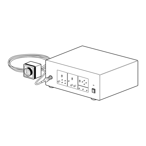
AC Inlet cable Camera control unit Feature Thank you for purchasing the DZ-VCA3U MICRO HD CAMERA. • Compact, lightweight design Thanks to the incorporation of 1/3-inch CCDs, the camera head’s outer dimensions have been reduced to a compact 44 (W) x 51.4 (H) x 57.7 (D) mm and its weight to only 100g. -
Page 3: Applications
Before use, please read the safety information and precautions contained in the following pages to ensure safe use of your new MICRO HD CAMERA. Importer’s name & address J.P.C.: JVC PROFESSIONAL PRODUCTS COMPANY 1700 Valley Road, Wayne NJ 07470 TEL: (973) 317-5000 FAX: (973) 317-5030 Cart information (1) Cart should meet with UL2601-1. -
Page 4: Safety Precautions
WARNING: This MICRO HD CAMERA should be used with a power supply of AC 120 V , 60 Hz only. To prevent electric shocks and fire hazards, DO NOT use any other power supply. WARNING: This camera head with camera cable and camera control unit are not sterilized. -
Page 5: Important Product Safety Instructions
INSTALLATION AND DISPOSAL 1. Grounding or Polarization Precautions should be taken so that the grounding or polarization of an appliance is not defeated. 2. Power Sources Operate your product only from the type of power source indicated on the marking label. If you are not sure of the type of power supply to hospital, consult your product dealer or local power company. - Page 6 48 H) Notes: • Always follow the recommended procedure from the manufacturer of your EO sterilization system when sterilizing the DZ-VCA3U camera head with cable and adapter. • Never sterilize camera head without connecting endoscope adapter and connector cap.
-
Page 7: Precautions
L Whenever an anomaly (unusual noise, smell or smoke) occurs, immediately turn off the main unit’s power, unplug the power cord, and consult your nearest JVC dealer. L Never use digital equipment such as portable telephones or video cameras when using this unit as this may cause a malfunction. -
Page 8: Inspection And Maintenance
Inspection and maintenance The product and its components must be inspected regularly by a specialist. (The product should be inspected once a year). Camera Head Section 1. Leave installation of the product to a specially trained service personnel. 2. Connect the optional endoscope adapter DZ-E3U or DZ-E33U to lens mount of camera head. -
Page 9: Connections
L Connection example DT-V1900CG (Optional) SR-W7MAU (Optional) Video S(Y/C) Out NTSC OUT ~AC IN To each equipment Notes: • Use the above composition of device or its equivalent. • Do not connect this camera to equipment other than that depicted in these connection diagrams. •... -
Page 10: Names Of Parts And Their Functions
Camera control unit (front panel) CAMERA ADJUST [POWER] power switch and power indication When switching power on again after it is just switched off: Wait for more than 5 seconds before switching it on. [CAMERA] camera cable connector Connect to camera head. [OUTPUT LEVEL] output level controller section Set output level automatically or manually. -
Page 11: Camera Control Unit (Rear Panel)
Camera control unit (rear panel) ~AC IN [AC INPUT] power input connector To input AC120V. Equal-potential connector Cover for extension slot Remove the cover to install an optional device in this slot. [NTSC OUTPUT] NTSC output section Output of DV signals, Y/C(S) signals, VBS (compos- ite video signals). -
Page 12: Output Level Control Section
Output level control section OUTPUT LEVEL AUTO MANUAL ADJUST GAIN SHUTTER GAIN switch [AUTO] Adjusts gain automatically. In this mode, the [GAIN UP]/[GAIN DOWN] button [SHUTTER UP]/[SHUTTER DOWN] button disabled. [MANUAL] Set to this position when adjust the [GAIN] and [SHUTTER] manually. -
Page 13: White Balance Control Section
White balance control section OUTPUT LEVEL WHITE BALANCE AUTO MANUAL CAMERA SETTING ADJUST GAIN SHUTTER WHITE BALANCE switch SETTING button R/B button [AUTO] When set to this position, the camera is automatically set to a pre-adjusted white balance. To automatically readjust the while balance, use [SETTING] button [MANUAL] When adjusting the white balance manually, set to this... -
Page 14: Mode Control Section
Mode control section OUTPUT LEVEL AUTO MANUAL CAMERA ADJUST GAIN SHUTTER ENHANCE button To set enhance. By pressing this button, LED will light up, and the enhance will be functional. Press it again, then LED will light off and the emphasis will disappear. - Page 15 L MENU I N D I C A T I O N 1 I D / C O D E I N D I C A T I O N 2 G A I N & S H U T I N D I C A T I O N 3 O F F I D / C O D E...
- Page 16 [ID/CODE] menu Edit ID/CODE that can be displayed on the screen. • Select from INDICATION 1, 3 menu to see if it can be displayed. • Message is up to 24 alphanumeric characters. • Characters that can be used: A-Z, 0-9, ., :, -, /, and space. [DATE&TIME] menu To change date and time setting, and date display format.
-
Page 17: Basic Operation
White balance adjustment a AUTO SETTING button WHITE BALANCE AUTO MANUAL SETTING BLUE a MANUAL WHITE BALANCE switch WHITE BALANCE AUTO MANUAL SETTING BLUE R/B volume control While watching the monitor, shoot a white object with full screen under the same lighting condition as actual shooting. Set the WHITE BALANCE switch to [AUTO]. -
Page 18: Operation Of Micro Hd Camera
Check that picture taken by camera can be displayed on the monitor. 7. Operate each device according to its operating procedure. Note : Consult JVC service personnel or authorized dealer when connecting the system for the first time. AC 120V yourself. -
Page 19: Connector
a Camera cable connector input/output terminals (CCU side) Symbols indicated on this equipment have the following meanings Attention, consult ACCOMPANYING DOCUMENTS Alternating current Off (power: disconnection from the mains) On (power: connection to the mains) TYPE OF APPLIED CF EQUIPMENT 1. -
Page 20: Specifications
Design and specifications subject to change without notice. MICRO HD CAMERA DZ-VCA3U Camera head section L Image sensing device L Shooting system L Color separation optical system L Number of effective pixels L Camera output L Lens mount L Dimensions... - Page 21 L Outer dimensions Camera head (Front) Camera control unit OUTPUT LEVEL WHITE BALANCE AUTO MANUAL AUTO MANUAL CAMERA SETTING ADJUST GAIN SHUTTER (Front) NTSC OUT ~AC IN (Rear) (Top) 57.2 12.7 57.7 (Side) (Bottom) MENU SETTING POWER BLUE ENHANCE FREEZE GENLOCK SXGA OUT HD OUT...
-
Page 22: Optional Equipments
: Applicable for EO • Weight : 102g (3.6 oz) TECHNICAL AND SERVICE ASSISTANCE JVC offers technical and customer service assistance. Please contact us at the following address. Importer’s name & address J.P.C.: JVC PROFESSIONAL PRODUCTS COMPANY 1700 Valley Road, Wayne NJ 07470... -
Page 23: Warranty And After-Sales-Service
Warranty record confirmation and safekeeping This product is sold with a warranty card attached. Warranty card has been delivered to sales dealer of this product. Please check your particulars and the record after filling, and keep it properly. L Warranty period: Warranty period is one year from the date of purchase. - Page 24 VICTOR COMPANY OF JAPAN, LIMITED Printed in Japan COPYRIGHT 2002 VICTOR COMPANY OF JAPAN, LTD. 0902-MN-SW-SW...