JVC CD/DVD Library MC-8200LU Instructions Manual
Cd/dvd library
Hide thumbs
Also See for CD/DVD Library MC-8200LU:
- Instructions manual (138 pages) ,
- Service manual (71 pages) ,
- Instructions manual (138 pages)
Table of Contents
Advertisement
Available languages
Available languages
Quick Links
CD/DVD LIBRARY
BEDIENUGSANLEITUNG : CD/DVD BIBLIOTHEK
MANUEL D'INSTRUCTIONS : BIBLIOTHEQUE CD/DVD
CD/DVD
MC-8200LU
MC-8600LU
For Customer Use:
Enter below the Model No. and Serial
No. which is located on the rear of the
cabinet. Retain this information for
future reference.
Model No.
MC-8200LU / MC-8600LU
Serial No.
MC-8200LU
This instruction book is made from 100% recycled paper.
INSTRUCTIONS
MC-8600LU
LST0168-001B
Advertisement
Chapters
Table of Contents

Related Manuals for JVC CD/DVD Library MC-8200LU

Summary of Contents for JVC CD/DVD Library MC-8200LU
- Page 1 CD/DVD LIBRARY BEDIENUGSANLEITUNG : CD/DVD BIBLIOTHEK MANUEL D’INSTRUCTIONS : BIBLIOTHEQUE CD/DVD CD/DVD MC-8200LU MC-8600LU For Customer Use: Enter below the Model No. and Serial No. which is located on the rear of the cabinet. Retain this information for future reference. Model No.
- Page 2 These are general IMPORTANT SAFEGUARDS and certain items may not apply to all appliances. 1. Read all of these instructions. 2. Save these instructions for later use. 3. All warnings on the product and in the operating instructions should be adhered to. 4.
-
Page 3: Laser Product
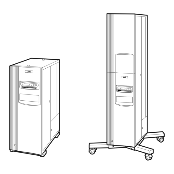
For Europe IMPORTANT The wires in this mains lead are coloured in accordance with the following code: GREEN - and - YELLOW: BLUE: BROWN: As the colours of the wires in the mains lead of this apparatus may not correspond with the coloured markings identifying the terminals in your plug. - Page 4 Thank you for purchasing the JVC MC-8200LU/8600LU CD/DVD Library Special Features The MC-8200LU/8600LU CD/DVD Library is a highly reliable and durable disc changer equipped with large capacity and high access speed to cope with the ever-changing needs of the rapidly developing information network age. This model is suitable for business as well as home use.
-
Page 5: Table Of Contents
CONTENTS 1. PRECAUTIONS ... 5 Installation and handling precautions ... 5 Disc handling precautions ... 5 2. NAMES AND FUNCTIONS OF PARTS ... 6 2-1.Front panel, right side panel, rear panel... 6 2-2. Interior ... 7 2-3. Magazine numbers, tray numbers, disc numbers ... 8 2-4. -
Page 6: Precautions
Please make sure to use the equipment in an appro- priate environment. (8) Backup • JVC cannot accept responsibility for any loss of data and/or any other direct and indirect damage caused by the use or malfunctioning of this equipment. We therefore strongly ad- vise that all important data should be fully backed up in case of unexpected loss. -
Page 7: Names And Functions Of Parts
2. NAMES AND FUNCTIONS OF PARTS 2-1. Front panel, right side panel, rear panel POWER switch ... Turns the main unit power on/off. " | ":ON. " POWER Indicator ... Lights up when the POWER switch is turned on. Blinks in case of error during operation. LCD Display Panel ... -
Page 8: Interior
2-2. Interior Mail slot ... Used for disc insertion/ejection. & Mail slot transport lock ... Locks the mail slot during transport. Magazines ... Each magazine contains 50 trays accommodating up to 50 discs. Drive bays ... Accommodation for up to 6 drive units is compatible with this product. The bays are num- bered 1, 2, 3,4 5 and 6 from the bottom. -
Page 9: Magazine Numbers, Tray Numbers, Disc Numbers
Names and Functions of Parts 2-3. Magazine numbers, tray numbers, disc numbers The internal layout of the magazine and the numbers assigned to the magazines, trays and discs are as shown below. Magazine number ... This is the number assigned to each of the 4 or 12 sets of magazines. The error message dis- played when a magazine is inserted incompletely refers to the magazine number. -
Page 10: Internal Scsi Cable
2-4. Internal SCSI cable The SCSI connections inside the main unit (the Changer) are explained below: The SCSI board, drive units and an SE (single-ended)/LVC (Low Voltage Differential) conversion board are daisy-chain connected by an internal SCSI cable. The length of the internal SCSI cable should be about 1.0 meter. Interior ●... -
Page 11: Setup
Execute the automatic drive detection mode. Completion A large number of discs can be loaded quickly(bulk load). Please have your dealer or nearest JVC service center perform this task. 3-1. Attaching the casters The MC-8600LU comes standard with designated casters. -
Page 12: Opening The Transport Lock
3-2. Opening the transport lock Open the door by inserting the key and turning it counterclockwise (90°) to unlock the door. Open the transport lock of the mail slot. • Using a philps screwdriver, continue to turn the lock counterclockwise until the lock is completely disen- gaged and moves outwards. -
Page 13: Removing The Transport Protective Materials
• In the case of re-transporting, it is necessary to remove all the discs and re-attach the protective transport materials using the reverse procedure to the above. When this operation is required, please consult your dealer or nearest JVC- authorized service agent. -
Page 14: Removing The Optional Carrier Transport Lock Screw
3-4. Removing the optional carrier transport lock screw When the MC-CF10U is installed, its special transport lock should be removed in addition to its being unlocked as detailed in "3-2. Opening the transport lock" on page E11. Use the following procedure when unlocking the optional carrier transport lock. -
Page 15: Connecting The Power Cord And Cables
SCSI host adapter: PCI SCSI-2U3WL by Antares Microsystems Co., Ltd. SCSI cable: ACK-68V-68HD-LVD (2 m) by ADAPTEC Co., Ltd. Please consult your local JVC service center if a cable of a length other than the above mentioned or one that has been supplied by another manufacturer has been fitted. -
Page 16: Control Panel Operations And Lcd Display
4. CONTROL PANEL OPERATIONS AND LCD DISPLAY The switch operation and LCD display system has three operation and display modes as described below. Normal display ... This mode includes two patterns, one of which is displayed automatically when the equipment starts up normally. -
Page 17: Event Display
Control Panel Operations and LCD Display 4-3. Event display Power on P O W E R During initialization I N I T I A L I Z I N G Error occurrence ( a See “10-2. Error code list” on page E31.) E R R O R O C C U R R E D ! During door opening ( a See “5. -
Page 18: Display And Operation Sequence
4-4. Display and operation sequence The sequence of display and operation after turning the power on is as shown below. Power On POWER ON INITIALIZING MODE Normal display Pattern 1 SELECT SELECT Pattern 2 1. TOTAL SELECT 2. CR SELECT SELECT 9. -
Page 19: Door Opening/Closing
5. DOOR OPENING/CLOSING Once the transport locks have been released and the power has been turned on for the first time, the door is locked by an internal safety lock in addition to the key so that the door cannot be opened with the key alone. In order to open the door with the key under these conditions, either maintain or turn on the power supply if it has not been turned on yet, and perform the following operations before inserting and turning the key. -
Page 20: Mail Slot
6. MAIL SLOT 6-1. Disc loading CAUTION Do not load or eject a disc before the mail slot has stopped completely. It may not only damage the disc but also cause the equipment to malfunction because of excessive force being applied during opening and closing. -
Page 21: Import/Export Operation
Mail Slot 6-2. Import/export operation When loading/ejecting discs from any chosen tray by the mail slot without the control of the host computer, follow the proce- dure shown below. • During the import/export operation, the host computer commands which include the carrier operations cannnot be ex- ecuted. - Page 22 When the mail slot automatically opens, place the desired disc on the tray (number is displayed on the LCD). ( a See "6-1. Disc loading" on page E19.) •To remove a disc, lift it out of the tray. •When the following message appears on the LCD display, it is possible that the transport lock of the mail slot has not been properly released.
-
Page 23: Drive Units
Be sure to read the instruction manuals of the drive units before proceeding to any of the following work. • Note that certain device drivers are incompatible with the simultaneous use of more than one type of drive (mixed use). Please consult your dealer or nearest JVC service center. 7-1. Removing the panel Open the door. -
Page 24: Setting The Scsi-Id Numbers, Etc
7-3. Setting the SCSI-ID Numbers, etc. s Procedure for setting the SCSI-ID No. and other jumper settings. Please refer to the specified section(s) of the corresponding drive instruction manual. s Make sure to turn the power OFF before starting the procedure. If the procedure is carried out with the power ON, it will cause malfunction. -
Page 25: Installing The Panels
Drive Units 7-5. Installing the panels CAUTION s Check the installation screws and cables before installing the panel. Insufficient connections may cause malfunctions. Attach rear and side panels. • Screw the panels on, following the procedure in "7-1 Removing the panel" on page E22 in the reverse order. Close the door ( a See "5. -
Page 26: Drive Type Display
7-7. Drive type display Check the types of the installed drives as follows. Press the MODE key while the LCD display is in nor- mal display mode (to display Menu display). Press the SELECT key 8 times (to display "9. DRIVE DISPLAY"). -
Page 27: Setting The Scsi-Id Numbers Of The Main Unit
8. SETTING THE SCSI-ID NUMBERS OF THE MAIN UNIT Perform the following operations when changing the setting of the SCSI-ID Nos. of the main unit (changer). In the normal display mode, press the MODE switch. (the menu display returns.) Press the SELECT key 5 times. ("6. -
Page 28: Magazines
9. MAGAZINES CAUTION • Do not use a magazine which has been damaged (e.g. dropped), as normal operation cannot be accomplished with such a magazine. In addition, the use of such a magazine may damage the internal mechanism. • The magazines and trays used with the MC-1000/2000 series CD-ROM Library and MC-7000 series DVD-RAM Library are not compatible with those used with the MC-8000 series CD/DVD Library. -
Page 29: Loading/Replacing The Discs
Magazines 9-2. Loading/replacing the discs CAUTION • When loading discs directly into the magazine trays without using the mail slot, be careful not to damage the magazines and trays. • A disc may become impossible to write/read due to dust, fingerprints, scratches, etc. adhering to the disc surface. Please handle it carefully. -
Page 30: Automatic Disc Checking Function
9-3. Automatic disc checking function If a magazine was removed and reinstalled after the power had been turned on, this function will automatically check the disc status inside the magazine. Checking the operation modes. Press and hold the MODE switch for more than 5 seconds. •... -
Page 31: Error Codes
• When an error occurs, write down the error code before turning the power off, except in the case of an urgent problem such as smoke. • When an error occurs, make sure not to turn off the power in order to prevent further problems such as disc damage, and contact your dealer or nearest JVC service center immediately. MODE SELECT... -
Page 32: Error Code List
These errors indicate that the disc is not being moved normally. As the errors cannot be canceled by turning the power off and then on again, please contact your dealer or local JVC-authorized service agent in order to restore normal operation. -
Page 33: Error History Display
Error Codes 10-4. Error history display The history of past errors can be displayed as described below. In the normal display mode, press the MODE key. (The menu display appears.) Press the SELECT key once. ("2. ERROR DISPLAY” appears.) Press the ENTER key. (Select “2. -
Page 34: Access Counts
11. ACCESS COUNTS Access counts of the main unit (changer) and each unit (carrier, drives 1 - 6 and color disc printer) can be checked using this function. In the normal display mode, press the MODE switch. (The menu display appears.) Press the SELECT key 6 times. -
Page 35: Specifications
• The production of a particular drive may be discontinued without prior notice. Therefore, a replacement drive may be changed to a different model. • JVC does not provide a warranty in the case of software not functioning correctly as a result of a drive being replaced or added. - Page 36 CD/DVD-BIBLIOTHEK MC-8200LU BEDIENUNGSANLEITUNG MC-8600LU...
- Page 37 ERLÄUTERUNG DER AUFKLEBER KLASSENSCHILD GEHÄUSERÜCKSEITE. CLASS 1 LASER PRODUCT Hinweis: (1) Der Klassifizierungsaufkleber befindet sich auf der Geräterückseite. WICHTIG FÜR LASERPRODUKTE 1. LASER KLASSE 1. 2. GEFAHR: Unsichtbare Laserstrahlung, falls die Sicherheitsverriegelung beim Öffnen des Laufwerks versagt oder abgestellt wird. Direkte Bestrahlung muß vermieden werden.
- Page 38 Vielen Dank für den Erwerb einer CD/DVD-Bibliothek MC-8200LU/MC-8600LU von JVC. Besonderheiten Die MC-8200LU/8600LU CD/DVD-Bibliothek ist ein äußerst zuverlässiger Disc-Wechsler mit hoher Aufnahmekapazität und hoher Zugriffgeschwindig-keit, um den sich stets ändernden Informationsnetzwerken gerecht zu werden. Dieses Modell kann im Büro sowie zu Haus eingesetzt werden.
- Page 39 INHALTSVERZEICHNIS 1. VORSICHTSMASSNAHMEN ... 5 Hinweise zum Aufbau und zur Handhabung ... 5 Vorsichtshinweise beim Umgang mit Discs ... 5 2. BEZEICHNUNG UND FUNKTION DER TEILE ... 6 2-1. Frontplatte, rechte Seitenwand und Rückseite ... 6 2-2. Innenansicht ... 7 2-3.
-
Page 40: Vorsichtsmassnahmen
Laufwerke stark verkürzen. Benutzen Sie das Gerät daher nur innerhalb der vorgeschriebenen Klimabedingungen. (8) Datensicherung (“Backups”) • JVC kann keine Haftung für den Verlust von Daten oder für andere direkte bzw. indirekte Schäden übernehmen, die sich aus evtl. Funktionsstörungen des Geräts ergeben. Wir empfehlen Ihnen daher dringend, von Zeit zu Zeit entsprechende Datensicherungen („Backups“) vorzunehmen. -
Page 41: Bezeichnung Und Funktion Der Teile
2. BEZEICHNUNG UND FUNKTION DER TEILE 2-1. Frontplatte, rechte Seitenwand und Rückseite Netzschalter (POWER) ... Schaltet die Spannungsversorgung der Haupteinheit ein/aus. " | ": Ein, " Betriebsanzeige ... Leuchtet auf, wenn der Netzschalter (POWER) eingeschaltet ist. Blinkt bei Fehlern während des Betriebs. -
Page 42: Innenansicht
2-2. Innenansicht Einlegeschublade ... Zum Einlegen/Entnehmen der Discs. & Transportverriegelung der Einlegeschublade ... Sichert die Einlegeschublade während des Transports. Magazin ... Jedes Magazin enthält 50 Träger und kann so bis zu 50 Discs aufnehmen. Laufwerkseinschübe ... Für dieses Produkt sind bis zu 6 Laufwerke möglich. Die Einschübe sind von unten nach oben mit 1, 2, 3, 4, 5 und 6 durchnumeriert. -
Page 43: Magazinnummern, Trägernummern, Disc-Nummern
Bezeichnung und Funktion der Teile 2-3. Magazinnummern, Trägernummern, Disc-Nummern Die interne Aufteilung eines Magazins und die Nummern, die den Magazinen, Trägern und Discs zugeordnet sind, sind in der Abbildung unten dargestellt. Magazinnummer: ... Nummer, die die 4 bzw. 12 eingesetzten Magazine bezeichnet. Fehlernachrichten bei nicht richtig eingelegten Magazinen beziehen sich auf die Magazinnummer. -
Page 44: Internes Scsi-Kabel
2-4. Internes SCSI-Kabel Die SCSI-Anschlüsse im Gerät (Disc-Wechsler) werden weiter unten erläutert: Die SCSI-Karte, die Laufwerke und die SE/LVD-Karte (Single-ended/Low Voltage Differential) sind geräteintern mittels eines SCSI-Kabels in Reihe geschaltet. Die Länge des internen SCSI-Kabels sollte ca. 1,0 m betragen. Innenansicht Laufwerk 6 Laufwerk 5... -
Page 45: Inbetriebnahme
Ende Mit der Initialisierung des Steuerungscomputers fortfahren Es kann eine große Zahl von Discs schnell geladen werden. Lassen Sie bitte den Einbau von Ihrem Händler oder beim nächstgelegenen JVC Kundendienstcenter ausführen. 3-1. Laufrollen anbringen MC-8600LU werden mit speziellen Laufrollen geliefert. -
Page 46: Transportverriegelung Lösen
3-2. Transportverriegelung lösen Schließen Sie die Tür auf, indem Sie den Schlüssel 90° gegen den Uhrzeigersinn drehen. Schließen Lösen Sie die Transportverriegelung der Einlegeschublade. • Drehen Sie die Verriegelung mit einem Kreuzschlitz- Schraubendreher gegen den Uhrzeigersinn; der Sicherungsstift ist dann gelöst. Lösen Sie die Transportverriegelung der Transportvorrichtung. -
Page 47: Transportschutzmaterial Entfernen
• Wenn Sie das Gerät erneut transportieren wollen, müssen Sie alle Discs entfernen und das Transportschutzmaterial in umgekehrter Reihenfolge wie oben beschrieben wieder anbringen. Falls dieser Eingriff notwendig sein sollte, wenden Sie sich bitte an Ihren JVC-Händler oder den nächstgelegenen JVC-Kundendienst. -
Page 48: Entfernung Der Transportverriegelungschraube Des Wahlweisen Wechselrobotiks
3-4. Entfernung der Transportverriegelungschraube des wahlweisen Wechselrobotiks Wenn der MC-CF10U installiert ist, sollte dessen spezielle Transportverriegelung nicht nur entriegelt sondern ebenfalls entsprechend "3-2. Transpotverriegelung lösen" auf Seite G11 entfernt werden. Folgendes Verfahren für Entriegelung der Transportverriegelung des wahlweisen Wechselrobotiks anwenden. Die Transportverriegelungschraube entfernen (für wahlweisen Wechselrobotik). -
Page 49: Netzkabel Und Andere Kabel Anschließen
SCSI-Hostadapter: PCI SCSI-2U3WL der Firma Antares Microsystems Co., Ltd. SCSI-Kabel: ACK-68V-68HD-LVD (2 m) der Firma ADAPTEC Co., Ltd. Bitte lassen Sie sich von Ihrer JVC Kundendienststelle beraten, wenn eine von den obigen Angaben abweichende Kabellänge oder ein Kabel eines anderen Herstellers installiert wurde. -
Page 50: Bedienkonsole Und Lcd-Anzeige
4. BEDIENKONSOLE UND LCD-ANZEIGE Für Tastenbedienung und LCD-Anzeige gibt es drei Betriebs- und Anzeigemodi (siehe Beschreibung unten). Normalmodus ... Dieser Modus umfaßt zwei Anzeigemuster; eines davon wird automatisch angezeigt, wenn das Gerät normal startet. Es zeigt die Nummern der gerade in den Laufwerken befindlichen Discs. Menümodus ... -
Page 51: Ereignismodus
Bedienkonsole und LCD-Anzeige 4-3. Ereignismodus Einschalten P O W E R Initialisierung läuft I N I T I A L I Z I N G Fehler ( a Siehe “10-2. Fehlercodeliste” auf Seite G31.) E R R O R O C C U R R E D ! Beim Öffnen der Tür ( a Siehe “5. -
Page 52: Anzeige Und Bedienungsablauf
4-4. Anzeige und Bedienungsablauf Der Ablauf von Anzeige und Bedienung nach dem Einschalten ist nachfolgend abgebildet. Einschalten POWER ON INITIALIZING Normalmodus Anzeigemuster 1 SELECT SELECT Anzeigemuster 2 1. TOTAL SELECT 2. CR SELECT SELECT 9. DR6 SELECT 10. FL *1. Wenn der wahlweise MC-CF10U Wechselrobotik installiert ist. -
Page 53: Tür Öffnen/Schliessen
5. TÜR ÖFFNEN/SCHLIESSEN Wenn die Transportverriegelung gelöst und das Gerät zum ersten Mal eingeschaltet wurde, ist die Tür zusätzlich mit einem internen Sicherheitsschloß gesichert, so daß sie nicht mit dem Schlüssel allein geöffnet werden kann. Um unter diesen Umständen die Tür zu öffnen, müssen Sie das Gerät einschalten oder eingeschaltet lassen und wie folgt vorgehen, bevor Sie den Schlüssel einstecken und umdrehen: Tür öffnen Drücken Sie im Normalmodus die Taste MODE. -
Page 54: Einlegeschublade
6. EINLEGESCHUBLADE 6-1. Disc einlegen ACHTUNG Die Einlegeschublade muß vollständig stillstehen, wenn Sie eine Disc einlegen oder entnehmen möchten. Die Disc könnte andernfalls beschädigt werden, und es können Fehler auftreten, wenn beim Öffnen und Schließen zuviel Kraft angewendet wird. Disc einlegen/entnehmen Wenn eine Ablage durch Hauptrechnersteuerung oder Import/Export-Operation ( a S.G20) zum Postschlitz transportiert wird, öffnet sich der Postschlitz nach... -
Page 55: Import/Export Von Discs
Einlegeschublade 6-1. Disc einlegen 6-2. Import/Export von Discs Um Discs eines beliebigen Trägers ohne Ansteuerung durch den Steuercomputer zu laden oder auszuwerfen, verfahren Sie wie folgt. • Während der Durchführung von Import oder Export können keine Befehle des Steuerungscomputers (einschließlich Transportoperationen) durchgeführt werden. - Page 56 Die Einlegeschublade öffnet sich automatisch. Die Nummer des gerade bearbeiteten Trägers erscheint auf der LCD- Anzeige. Legen Sie die gewünschte Disk auf den Träger. ( a Siehe “6-1. Disk einlegen” auf Seite G19.) •Um eine Disk zu entfernen, entnehmen Sie sie aus dem Träger. •Wenn die folgende Nachricht auf der LCD-Anzeige erscheint, kann es sein, daß...
-
Page 57: Laufwerke
Bedienungsanleitungen der Laufwerke durchlesen. • Beachten das bestimmten Einheitentreiber nicht kompatibel sind für die gleichzeitige Anwendung mit mehr als einem Laufwerktyp (Mischanwendung). Bitte wenden Sie sich in solch einem Fall an Ihren Händler oder das nächstgelegene JVC Kundendienstcenter. 7-1. Abdeckung entfernen Öffnen Sie die Tür... -
Page 58: Einstellen Der Scsi Id-Nr., Usw
7-3. Einstellen der SCSI ID-Nr., usw. s Die SCSI ID-Nr. für das Laufwerk usw. eingeben. Für die zur Eingabe erforderlichen Schritte sich auf die Bedienungsanleitung des als Sonderausstattung erhältlichen Laufwerks beziehen. s Vergewissern Sie sich, daß das Gerät ausgeschaltet ist, bevor Sie mit den Einstellungen beginnen. Eine Änderung der Einstellungen bei eingeschaltetem Gerät führt zu Störungen und Fehlfunktionen. -
Page 59: Abdeckungen Einbauen
Laufwerke 7-5. Abdeckungen einbauen s Überprüfen Sie den Sitz der Schrauben und der Kabelverbindungen, bevor Sie die Abdeckungen einbauen. Mangelhafter Kontakt kann zu Fehlfunktionen führen. Bringen Sie die Seiten- und Rückwand wieder an. • Schrauben Sie die Abdeckungen fest. Führen Sie dazu “7-1. Abdeckung entfernen” von Seite G21 in umgekehrter Reihenfolge aus. -
Page 60: Laufwerktypanzeige
7-7. Laufwerktypanzeige Überprüfen Sie die jeweilige Laufwerksausführung wie folgt.. Bei normalen Anzeigenbetrieb der LCD-Anzeige die MODE-Taste betätigen (für Einstellung der Menüanzeige). Die SELECT-Taste 8mal betätigen (für Anzeige von "9. DRIVE DISPLAY"). Die ENTER-Taste betätigen (für Einstellung von "9. DRIVE DISPLAY"). Der Laufwerktyp in jedem Laufwerkfach wird angezeigt. -
Page 61: Einstellen Der Scsi-Id-Nummern Der Haupteinheit
8. EINSTELLEN DER SCSI-ID-NUMMERN DER HAUPTEINHEIT Führen Sie zum Ändern der SCSI-ID-Nummern der Haupteinheit (Wechsler) die folgenden Schritte durch: Drücken Sie im Normalmodus die Taste MODE. (Die Menuanzeige erscheint.) Drücken Sie die Taste SELECT fünfmal. ("6. ID No. SET MODE" erscheint.) Drücken Sie die Taste ENTER. -
Page 62: Magazine
9. MAGAZINE ACHTUNG • Verwenden Sie kein Magazin, das durch Fall oder andere Einflüsse beschädigt wurde; mit solchen Magazinen ist kein normaler Betrieb möglich. Außerdem kann die Verwendung fehlerhafter Magazine den internen Mechanismus beschädigen. • Die Magazine und Ablagen der MC-1000/2000 Serie der CD-ROM-Bibliothek und der MC-7000 Serie der DVD-RAM- Bibliothek sind nicht kompatibel mit denen, die für die MC-8000 Serie verwendet werden. -
Page 63: Discs Einlegen/Wechseln
Magazine 9-2. Discs einlegen/wechseln ACHTUNG • Wenn Discs nicht über die Einlegeschublade, sondern direkt in die Magazinträger eingelegt werden, achten Sie darauf die Magazine und Träger nicht zu beschädigen. • Durch Kratzer, Staub, Fingerabdrücke und andere Oberflächenverschmutzungen kann das Lesen/Beschreiben einer Disc unmöglich werden. -
Page 64: Automatische Discs-Testfunktion
9-3. Automatische Discs-Testfunktion Wenn ein Magazin entfernt und nach Einschalten des Geräts wieder eingesetzt wurde, wird der Disc-Bestand in diesem Magazin automatisch überprüft. Feststellen der Betriebsart Drücken und halten Sie die Taste MODE für mindestens fünf Sekunden. • Ab Werk ist die automatische Discs-Testfunktion eingeschaltet. Automatische Discs-Testfunktion EIN A U T O D I S C... -
Page 65: Fehlercodes
• Schreiben Sie im Fehlerfall den Fehlercode auf, bevor Sie das Gerät ausschalten, außer in Notfällen wie etwa bei Rauchentwicklung usw. • Bei Betriebsstörungen sollten Sie unbedingt eine Ausschaltung vermeiden, um etwaigen Folgeschäden, wie Beschädigung des Speichermediums etc., entgegenzuwirken, und sich umgehend mit Ihrem JVC Fachhändler oder JVC Kundendienst in Verbindung setzen. MODE DISC = 124 CODE = CU - 07 Discs-Nr.: Zeigt die Nummer der Disc, auf die zum Zeitpunkt des Fehlers... -
Page 66: Fehlercodeliste
10-3. Aufhebung der Fehler “20”, “21” und “64” Diese Fehlercodes zeigen an, dass die Disc nicht einwandfrei transportiert wird. In diesem Fall ist die Fehlerbehebung durch Aus- und erneutes Einschalten nicht möglich. Wenden Sie sich zur Fehlerbehebung bitte an Ihren zuständigen JVC Kundendienst. Entriegelungsvorgang ACHTUNG Wenn die Entriegelung durchgeführt wird, ohne zuvor die im Träger vorhandene Disk oder das Diskfach zu entfernen, können... -
Page 67: Fehler Und Ihre Behebung
Fehlercodes 10-4. Anzeige des Fehlerprotokolls Eine Protokollierung früher aufgetretener Fehler läßt sich wie folgt anzeigen. Drücken Sie im Normalanzeigemodus die Taste MODE. (Die Menüanzeige erscheint.) Drücken Sie die Taste SELECT einmal. (“2. ERROR DISPLAY” wird angezeigt.) Drücken Sie die Taste ENTER. (Bestätigen Sie die Auswahl “2. -
Page 68: Zugriffszähler
11. ZUGRIFFSZÄHLER Die Zugriffszähler für die Haupteinheit (Wechsler) und für jede Untereinheit (Transportvorrichtung, Laufwerke 1-6 und Beschriftungsdrucker) können wie folgt abgelesen werden. Drücken Sie im Normalmodus die Taste MODE. (Die Menüanzeige erscheint.) Drücken Sie die Taste SELECT sechsmal. (“7. COUNT DISPLAY” erscheint.) Drücken Sie die Taste ENTER. -
Page 69: Technische Daten
• Der Herstellungsstopp von Laufwerkbaureihen ist ohne Vorankündigung vorbehalten. Bei einem Austausch kann daher ein Laufwerk aus einer anderen Baureihe zur Verwendung kommen. • JVC ist nicht haftbar für Software-Betriebsstörungen, wenn diese auf einen Austausch gegen Laufwerke anderer Baureihen oder auf eine Hinzufügung von Laufwerken anderer Baureihen zurück zuführen sind. - Page 70 BIBLIOTHEQUE CD/DVD MC-8200LU MANUEL D’INSTRUCTIONS MC-8600LU...
- Page 71 REPRODUCTION DES ETIQUETTES 1. ETIQUETTE DE CLASSIFICATION, SUR L'ARRIERE DU COFFRET. CLASS 1 LASER PRODUCT Remarque: (1) Le label de classification est placé sur le panneau arrière. IMPORTANT POUR LES PRODUITS LASER 1. PRODUIT LASER DE CLASSE 1 2. DANGER: Rayonnement laser invisible en cas d’ouverture et de défaillance.
- Page 72 Nous vous remercions d’avoir fait l’acquisition d’une bibliothèque CD/DVD JVC MC-8200LU et MC-8600LU. Particularités La bibliothèque CD/DVD MC-8200LU, MC-8600LU est un changeur de disques de haute fiabilité, grande capacité et vitesse d’accès élevée destiné à répondre aux besoins évolutifs de l’ère informatique. Ce modèle convient tant pour les applications professionnelles que privées.
- Page 73 SOMMAIRE 1. CONSIGNES ... 5 Conseils d’installation et de manipulation ... 5 Précautions à prendre pour manipuler les disques ... 5 2. NOMENCLATURE ET FONCTION DES COMPOSANTS ... 6 2-1. Panneau avant, côté droit, panneau arrière ... 6 2-2. Intérieur ... 7 2-3.
-
Page 74: Consignes
être sérieusement diminué e. Veillez à utiliser l’équipement dans un environnement approprié. (8) Sauvegarde • JVC ne peut accepter de responsabilité pour toute perte et/ou détérioration directe ou indirecte provoquée par l’utilisation ou la défaillance de cet appareil. Nous conseillons donc vivement de faire une sauvegarde de toutes les données importantes... -
Page 75: Nomenclature Et Fonction Des Composants
2. NOMENCLATURE ET FONCTION DES COMPOSANTS 2-1. Panneau avant, côté droit, Panneau arrière Interrupteur POWER ... Sert à la mise sous tension et hors tension de l'appareil . "I": marche; "O": arrêt. Témoin ... S'allume lorsque l'interrupteur POWER est sur MARCHE. Clignote s'il y a une erreur Affichage LCD ... -
Page 76: Intérieur
2-2. Intérieur Alvéole rectangulaire ... Sert à l’insertion/éjection des disques. & Verrouillage de transport du chargeur frontal ... Bloque l’alvéole pendant le transport. Magasin ... Chaque magasin contient 50 plateaux qui accueillent 50 disques. Emplacements pour les unités ... Accepte un maximum de 4 unités lecteurs. Les baies sont numérotées 1, 2, 3, Changeur ... -
Page 77: Numéros Des Magasins, Des Plateaux Et Des Disques
Nomenclature et fonction des composants 2-3. Numéros des magasins, des plateaux et des disques La disposition interne de chaque magasin et les numéros attribués aux magasins, plateaux et disques sont indiqués ci-dessous. Numéro de magasin .. Il s’agit du numéro attribué à chacun des 4 ou 12 jeux de magasins. Le message d’erreur qui s’affiche lorsque un magasin est incomplètement introduit se rapporte au numéro de ce magasin. -
Page 78: Câble Scsi Interne
2-4. Câble SCSI interne Les connexions SCSI à l’intérieur de l’unité principale (changeur) sont expliquées ci-dessous. La carte SCS, les unités et une carte de conversion SE (simple)/LVC (différentiel basse tension) sont raccordées en guirlande par un câble SCSI intérieur. La longueur de ce câble SCSI intérieur est d’environ 1,0 mètres. Inutilisé. -
Page 79: Installation
Exécutez le mode de détection d'unité lecteur automatique Un grand nombre de disques peut être chargé rapidement. Faites faire ce travail par votre revendeur ou le service technique JVC le plus proche. 3-1. Pose des pattes à roulettes Les modèle et MC-8600LU sont livrés avec des pattes à roulettes spéciales. -
Page 80: Déblocage Du Verrouillage De Transport
3-2. Déblocage du verrouillage de transport Ouvrez la porte en tournant la clé dans le sens anti-horaire (90°) pour la débloquer. Déverrouillé Verrouillé Débloquez le verrouillage de transport du chargeur fron- tal. • A l’aide d’un tournevis,dé vissez (dans le sens anti- horaire) pour faire sortir l’ergot. -
Page 81: Dépose Des Éléments De Protection De Transport
Répétez la même opération pour le magasin n° 2 et les suivants. • Pour tout nouveau transport, enlevez tous les disques et remettez les éléments de protection en procédant dans l’ordre inverse que ci-dessus. Dans ce cas, consultez votre revendeur ou le service technique JVC. -
Page 82: Retrait De La Vis De Verrouillage Du Chariot En Option
3-4. Retrait de la vis de verrouillage du chariot en option Quand le MC-CF10U est installé, sa vis de verrouillage doit être retirée en plus de son déverrouillage comme indiqué dans "3-2. Déblocage du verrouillage de transport" à la page F11. Procédez comme suit pour le déverrouillage du verrou de transport du chariot en option. -
Page 83: Branchement Du Cordon Secteur Et Des Câbles
Adaptateur hôte SCSI: PCI SCSI-2U3WL d’Antares Microsystems Co., Ltd. Câble SCSI: ACK-68V-68HD-LVD (2 m) d’ADAPTEC Co., Ltd. Veuillez consulter votre centre de service JVC local si un câble d’une longueur différente de celle précitée ou fourni par un autre fabricant a été installé. -
Page 84: Panneau De Commande Et Affichage Lcd
4. PANNEAU DE COMMANDE ET AFFICHAGE LCD Les touches et l'affichage LCD présentent trois fonctions et modes d’affichage comme indiqué ci-dessous : Affichage normal ... Ce mode compte deux écrans dont l'un est affiché automatiquement lorsque l'appareil est enclenché normalement. Les numéros des disques présents dans les unités sont affichés en temps réel. -
Page 85: Affichage Des Événements
Panneau de commande et affichage LCD 4-3. Affichage des événements Mise sous tension P O W E R Pendant l’initialisation I N I T I A L I Z I N G Apparition d’erreurs ( a Voir “10-2. Liste des codes d’erreurs” à la page F31.) E R R O R O C C U R R E D ! Pendant l’ouverture de la porte ( a Voir “5. -
Page 86: Affichage Et Succession Des Opérations
4-4. Affichage et succession des opérations La succession de l’affichage et des opérations après avoir mis l’appareil sous tension est indiquée ci-dessous. Mise sous tension POWER ON INITIALIZING Affichage normal Affichage 1 SELECT SELECT Affichage 2 1. TOTAL SELECT 2. CR SELECT SELECT 9. -
Page 87: Ouverture/Fermeture De La Porte
5. OUVERTURE/FERMETURE DE LA PORTE Après déblocage du verrouillage du transport et première mise sous tension, il subsiste un verrouillage supplémentaire de la porte. La clé mécanique ne suffit donc pas à l'ouvrir. Pour ouvrir la porte avec la clé dans ces conditions, mettez ou laissez l'appareil sous tension et effectuez les opérations suivantes avant d'introduire et de tourner la clé. -
Page 88: Chargeur Frontal
6. CHARGEUR FRONTAL 6-1. Chargement d'un disque ATTENTION Ne chargez ni n'éjectez de disque avant l'arrêt complet du chargeur frontal. Non seulement le disque risquerait d'être endommagé, mais l'équipement pourrait aussi tomber en panne en raison de la force excessive appliquée pendant l'ouverture et la fermeture. -
Page 89: Opération D'importation/Exportation
Chargeur frontal 6-2. Opération d'importation/exportation Pour le chargement/éjection de disque de l'un des plateaux par le chargeur frontal, sans commande de l'ordinateur, suivez la procédure indiquée ci-dessous. • Pendant l'opération d'importation/exportation, les commandes de l'ordinateur qui contrô lent les opérations du chariot ne peuvent pas être exécutées. - Page 90 Lorsque le chargeur s'ouvre , posez un disque sur le plateau (son nombre apparaît à l'affichage LCD). ( a Voir "6-1. Chargement d'un disque" à la page F19.) • Pour enlever un disque, soulevez-le du plateau. • Lorsque le message suivant apparaît à l’affichage LCD, il se peut que le verrouillage de transport de l’alvéole rectagulaire ne soit pas correctement débloqué.
-
Page 91: Unites Lecteurs
• Notez que certaines unités lecteurs sont incompatibles avec l'emploi simultané de plus d'un type de lecteur (utilisation combinée). Consultez votre revendeur ou le service technique JVC le plus proche. 7-1. Dépose du panneau •... -
Page 92: Détermination Des Numéros D'identification Scsi, Etc
7-3. Détermination des numéros d’identification SCSI, etc. s Régler le numé ro d'identification SCSI du lecteur. Consulter le mode d'emploi du lecteur pour les procédures de réglage. s N’oubliez pas de couper l’alimentation avant d’entamer la procédure. Si la procédure est effectuée avec l’alimentation enclenchée, il y a risque de perturbation. -
Page 93: Pose Des Panneaux
Unités lecteurs 7-5. Pose des panneaux sVérifiez les connexions de l'installation, les vis et les câbles avant de poser le panneau. Les connexions douteuses conduisent à des erreurs de fonctionnement. Posez les panneaux arrière et latéral. • Vissez les panneaux en inversant la procédure de “7-1 Dépose des panneaux” à la page F21. Fermez la porte. -
Page 94: Affichage Du Type De Lecteur
7-7. Affichage du type de lecteur Vérifiez le type des unités installées comme suit. Appuyez sur la touche MODE avec l'affichage LCD en mode d'affichage normal (pour afficher l'écran MENU). Appuyez 8 fois sur la touche SELECT (pour afficher "9. AFFICHAGE DES LECTEURS"). -
Page 95: Détermination Du Numéro D'identification Du Controleur Scsi Interne
8. DÉTERMINATION DU NUMÉRO D’IDENTIFICATION DU CONTROLEUR SCSI INTERNE Effectuez les opérations suivantes pour modifier les numéros d'identification SCSI de l'unité centrale (changeur). Sous l’affichage normal, appuyez sur MODE. (L'affichage menu apparaît.) Appuyez cinq fois sur SELECT. ("6. ID No. SET MODE" apparaît.) Appuyez sur ENTER. -
Page 96: Magasins
9. MAGASINS ATTENTION • N’utilisez pas de magasin endommagé par une chute ou autre choc; l’appareil ne peut pas fonctionner normalement avec de tels magasins. En outre, l’utilisation de tels magasins risquerait d’endommager le mécanisme interne. • Les magasins et plateaux utilisés dans la bibliothèque CD-ROM de série MC-1000/2000 et la bibliothèque DVD-RAM de série MC-7000 ne sont pas compatibles avec ceux utilisés avec la bibliothèque CD/DVD de série MC-8000. -
Page 97: Chargement/Remplacement Des Disques
Magasins 9-2. Chargement/remplacement des disques ATTENTION • Lorsque vous placez les disques directement sur les plateaux des magasins sans utiliser le chargeur frontal, veillez à n’endommager ni les magasins ni les plateaux. • Un disque peut devenir impossible à lire ou à écrire en raison de la poussière, de traces de doigts, de rayures, etc. sur sa surface. -
Page 98: Fonctionnement De Contrôle Automatique Des Disques
9-3. Fonctionnement de contrôle automatique des disques Si un magasin a été enlevé et réinstallé après mise sous tension, cette fonction vérifie automatiquement la situation des disques à l'intérieur du magasin. Vérification des modes de fonctionnement Maintenez MODE appuyé pendant plus de cinq secondes. •... -
Page 99: Codes D'erreur
• Quand une erreur survient, mettez bien hors tension pour éviter d’autres problèmes comme un dommage de disque, et contactez immédiatement votre revendeur ou le centre de service JVC le plus proche. MODE DISC = 124 CODE = CU - 07 N°... -
Page 100: Liste Des Codes D'erreur
Ces erreurs signifient que le disque ne bouge pas normalement. Comme elles ne peuvent pas être annulées en mettant hors tension puis sous tension, contacter le revendeur ou l’agent de service autorisé JVC pour rétablir le fonctionnement normal. Opération d’effacement ATTENTION Si l’opération d’effacement d’erreur est exécutée sans enlever le disque ou le tiroir à... -
Page 101: Affichage De L'historique Des Erreurs
Codes d’erreur 10-4. Affichage de l’historique des erreurs L’historique des erreurs antérieures peut être affiché comme indiqué ci-dessous. En affichage normal, appuyez sur MODE. (L’affichage du menu apparaît.) Appuyez une seule fois sur SELECT. (“2. ERROR DISPLAY” apparaît.) Appuyez sur ENTER. (Entrez la sélection “2. - Page 102 11. COMPTEURS D'ACCES Le nombre d'accès au changeur et à chaque unité (chariot, lecteurs et lecteurs-enregistreurs 1-6 et imprimante d'étiquettes) peut se vérifier à l'aide de cette fonction. En affichage normal, appuyez sur MODE. (Le menu apparaît.) Appuyez sur SELECT six fois. ("7.
-
Page 103: Caracteristiques Techniques
• Les spécifications pertinentes pour les unités se trouvent dans le mode d’emploi approprié. • Contactez le revendeur ou le centre de service JVC le plus proche à propos de la disponibilité/ compatibilité des unités qui ne figurent pas sur la liste. - Page 104 CD/DVD MC-8200LU MC-8600LU...
- Page 106 !"#$%&'(%) !"#$%&' !"#$ !"#$%& !"#$%& !"#$%&'()*+$,-.$/01/023456789:;,-.$"#<=>? !"#$%&'()* !"#$ !"#$% &'( )*+ ,-.,-/ 0123456 !"#$%&'( )*+,-.#$/0%&'1 %&'2#$3 453 67+8( 9:.;<= !" #$%&'()* !"#$ %&'()*&+,-./01234$ 56789:,-./$ ;<1234= !"#$%&'()*+,-./01 2 ➡ !"#$%&'$()* !" #$%&'()*+, -./012345678 9: !" #$%&'()*+$%,- ./01234 56789()*+ !" ∼ ! "#$%&' ( )*+,-./01 !"#OKR=ã...
- Page 107 !"#$%&' !"#$%&' !"#$%& !"#$ ! " !" !"#$% !"#$%&' !"#$%&'()*+ !"#$ !"# $%&' !"#$%&'()*+, !"# !"# !"# !"#$ !" !" !" !"# !"#$ !" !" ! "#$% !"#$% !"# !"# !" !"#$% !"#$% !"# !"#$% !"# !"#$%...
- Page 108 !"#$%&' !"#$% !"#$%&'()*+,-. /012345 !"#$%& !"#$%& '()& *+,-./0123 45 !"#$%&' !"#$%&'()*+ u !"#$%&'()*+,-./012 !"#$%&%'() *+,-./01) 23 !"#$%&!'()*+, -./01234 !"#$ !"#$%&' ()*+,- !"#$%&'()*+,&-./ '0120 !"#$!%&'()*+,- ./01(23 !"#$%&' ()O∼P !"#$%& !"#$% &'$% ()*+"$,+"-./ !"#$ %&'( )*#*+,-. !"#$%& !"#$%& '()"*+ ,-"#./012 !"# $%&'()*+, -.$/01234 !"#$ !"#$%&'()*#+,-#./0./1 !"#$%&'()*+,-.
- Page 109 !"#$%& !"#$ ! KKKKKKKKKKKKKKKKKKKKKKKKKKKKKKKKKKKKKKKKK KKKKKKKKKKKKKKKKKKKKKKKKKKKKKKKKKKKKKKKKKKKKKK !" KKKKKKKKKKKKKKKKKKKKKKKKKKKKKKKKKKKK !"#$% ∼ POWER !"#$ % & ' "( l !"#$% &'()*+,-."/0% !"#$%&'()*+ !"#$%&'()*+, !"#$%&#'()*+,- !"#$ !"#$%&'() !" #$%&'(" )*+ !"#$ !"# $ !"#$ %&'($ )*+,-./ !"#$%&'()*+,- !"# !" !"#$% !"# $ !"#$%&'() *#$+,-. !"#$%&'( MODE SELECT...
- Page 110 KKKKKKKKKKKKKKKKKKKKKKKKKKKKKKKKKKKKKKKKKKKKKK !"#$ KKKKKKKKKKKKKKKKKKKKKKKKKKK & KKKKKKKKKKKKKKKKKKKKKKKKKKKKKKKKKKKKKKKKKKKKKKKKKK !"# KKKKKKKKKKKKKKKKKKKKKKKKKKKKKKKK KKKKKKKKKKKKKKKKKKKKKKKKKKKKKKKKKKKKKKKKKKKKKK ⁄ !"#$ KKKKKKKKKKKKKKKKKKKKKKKKKKK ¤ !"#$%&' KKKKKKKKKKKKK ‹ !" !"#$%&' KKKKKKK › ! KKKKKKKKKKKKKKKKKKKKKKKKKKKKKKKKKKKKKKKKKKKKKKKKKKK ●= & ‹ ⁄ !"#$ !"#$%& !"# ! "#$ !"#$ !" #$%&'()*+ !"#$% &'()*+,- ./ 0 1 !"#$%&'() !"#$% !"#$%&'(%)*+ !"#$ !"#$%&'()*...
- Page 111 !"#$%& !" !"#$%&'()"#* +"* ,"-./012 !"#`OT MC-8200LU !"#$ !"#$ % !"# ! "#$%&'()*+,- ! "#$ %&'( !"#$ % "# !"#$%&'()*+,)-+.)/0 123/)*+ ! "#$%&'($%)*+,-./ ! 0 123 MC-8600LU &'()*+,- ./01234567# ./ 0.1 .23456 . !"#$%& ' ( !"...
- Page 112 p`pf !" #$%&p`pf !"#$ !"#pb páåÖäÉ=båÇÉÇ p`pf !"#$%&'( !"#$ ● !"#$%&"#%' ()*+, ● !"# !"#$% !"#isa içï=sçäí~ÖÉ=aáÑÑÉêÉåíá~ä !"#$%& !"#$%&'()*+,p`pf...
- Page 113 !"#$%&'( !" !"#$ %&'() *+,-.,/0123456 789:;<= >"#?%&@AB 6 !"#$%&'()*+,-./012 !"#$%&' !"#$%&'(#$) !"#$%& ※在操作过程中一定要将锁扣 扣好。 !"#$%& '()"*+,- !"#$% !"#$%&'(#)* MC-8200LU MC-8600LU !" !"#$%&' ()*+,-./0+1' .23 !"#$ %&'() == =W !"#$%&'( ! " # $ # % & !"#$%&'() !"#$%&'( !"#$%&'( !"#$%&'...
- Page 114 !"#$% !" !"#$%&'()* !"#$%& !"#$%&'( !" !"#$%& !"#$%&' !"#$%&'() !"#$ !"#$%&'( !"#$%&'()*+, - PJQ= !"#$%#&'()*+ ● !"#$% &'()*+,- !,./ !"#$ %&'() ! " # !"#$%& '()* !"#$%& !"#= !"#$% EQF= !"#$ ERF= !"#$% = a ESF= ! "#$ !"#$%&'( PJQ= !"#$%&'()*+,...
- Page 115 !"#$%&' !"#$%& '()*+,-./01.234 !"#$ a= ! `OT !"#$ !"#$ a= ! `OT !"#$%&'()!*+,-. ● !"#$% !"#$%& !"# !"# !"#$%&'()*!+,-.= !"#$ gs` !"#$...
- Page 116 !"#$%&'()*+ !"#$% !"# !"#$% !"#$%& '()*+,-./ !" #$% &'()*+,)#$- !"#$%&'()*+, !"#$%&'()*"#+,-./ ● !" !"#$%&!"'() !"#$p`pf !"# ! `OO !"#$%& p`pf !"#$% p`pf !"#$%&'()*+,- !" p`pf !"# a p`pf ● !" p`pf !"#$%&'( PJO= !"#$%&' PJO= !"# !" !"#$ p`pf !"#$%&'()* !"# $%&'( PJS= !"#$%&...
- Page 117 !"# $%&' !"#$%&'()*+,- ./0123456 !"#$%&'( )*+,-./ "0123 !"#$%&'() *+,-./ ● !"# ● !"#$ !" !"#$%&'()*+ !"#$%&'()*+,-./0 ● ● ● ● !"#$ !"#$%&'()*+, ● !"#$%&'()*+ ● !"# !" ! " ! " !"#$%&'()*+,-./0$ !"#$%&'()*+,-#./01"23456 47 !89:;<23=>45? 456789:/ ;<=>?@AB( = !"#$%"&'()*+,-./012345 !"#$%&'()* !"#$ ∼...
- Page 118 !"#$%&'()*+, !"#$%&'()*+,-./01 !"#$ !"#$%&' ()*+,-.$/!01+234 5623789:;+<.$=>?4 !"#$ !"#$%&' ()*+!,-' ./01!,-' 23456789!67./:;<= p ` p f !"#$%&'() *+, !"#$ !"#$%&' ()*+,$%&-./0123!45$%&6 789:;<=>6 ?@AB !"#$%&' !"# !"#!$%&'()*+ ,pbib`q !"# !"#$%&'()*+,%&'(- pbib`q jlab !"# !"#$ ! `PO ! `OS !"# =fa=kçK=pbq=jlab ! `OS p`pf ! `PP !"...
- Page 119 !"#$%&'()*+, !"# !" P O W E R !" I N I T I A L I Z I N G !" # a E R R O R O C C U R E D ! !"#$%& ' a E X E C U T I N G D O O R O P E N...
- Page 120 !"#$ !"#$%&'()*#+,- POWER ON INITIALIZING MODE SELECT SELECT SELECT 1. TOTAL SELECT 2. CR SELECT SELECT 7. DR4 SELECT 8. FL !" PUSH SEL. KEY SELECT PUSH SEL. KEY SELECT ENTER ENTER ● !"# !"#$%& ' ()*+"#,-./-0123-.4567p`pf ! " 1. NORMAL DISPLAY SELECT ENTER 2.
- Page 121 !" !"#$%&'()*+,-./012 3"452 !6%78&9:;0<2 =>&?@ABCDE2 FGH6%78 !"#$ !"#$%&'()*+,-./0 123"450 6789:;$%&'< !"#$%& jlab p b i b ` q jlab bkqbo RK=allo=lmbk=jlab !"#$ pbib`q !"#$%&' b u b ` r q f k d = a l l o lmbk=mol`bpp pbib`q !"#$% !"#$%&'() !"...
- Page 122 !" !"#$%&'()*+,-./01 234 56789 !"#$%& !"#$%!&'()* !"#$%&'( !"#$% !"#$%!&'() !"#$ !"#$%&'()*+,-( !"#$% & == =W !"#$%&'()*#+,-#./0./1 !"#$%&'()*+,-. == =W !"#$% & '()*+,-./01 !"#$ % POWER ● !"#$%&'( !"#$%&'()*+, ● !"#$%& !"#$%&'() !"#$%&'() *+,-./ 0123456789: !"#$%&'()$"#*+,-. /0123%&'*456 !"#$%&'()*+,-./0123456768#!"9:; < ! "#$%&'()*+,-./0123454678#$79:;<=> ? !"#$%&'()* + !, -./"01 !23456789:+ !2;<=>?@ !"#$%&'()*$+ ,-./012 4 :;<89'()1...
- Page 123 !"#$%"&!%' !"#$%&'()*+,-./01/23 ● ! "#$%&' ()*+,#-.,/0#12345 !"#$%& jlab UK=fjmloqLbumloq bkqbo UK=fjmloqLbumloq !"#$ pbib`q !"#$%&'()*+,- pbib`q !"#$%&'()* !"# !"#$%&'(P • !"#$%&'()* ! "#$%&'( )*+,-. • !"#$%& '()*+, bkqbo bkqbo !"#$% !"#$%&' !" #$%& !" ∼ !"#$% & !"#$% & ∼ ∼ &...
- Page 124 !"#$%& !"#$ %&$ !"# !"#$%!& • !"# !$%&'()* • PJO= C H E C K T H E P I N ! !"#$%&' jlab !"#= !"#$ !"# !"#$!"%&'()*+,-. / !" #$% &'()"*+,$%- . /"0123,4235 • T R A Y T R A Y N o .
- Page 125 ● !"#$ %&'()*+,-,./012!345678 9:;<=>?@8 !"#$%&'()*+,-./0123456 ● !"#$%&'() *+, !" !" a !" !"# !"#$ •= !"#$%&' p`pf •= !"# TJQ= ! pbJisa !"#$ p`pf pb •= !"# !"#$% &'()*+,-./-0-.1 2 a !"# !"#$%&'()*+,-. • !"#$%&'()* • = !"#$%&'()*+ • = !"#$%&'( !"#$%&'()* •...
- Page 126 !"#$ TJP p`pf !"#$%&'()*+,-.$/01234 !"#$%&'()*+,-. /012345 !"#$%&'()* !"#$%&'()*+ ,- !"# ∼ !"# $%&' ∼ !" !"#$%&'(#)*+,-./ • !" !"# !"#$%&'()*+,-./0 • ! " !"# j`JoQPQr ! isa !"#$% !"#$% • ! p`pf pb !"#$%&'( p`pf • p`pf pb ! p`pf isa !"#$%&...
- Page 127 !" !"#$%&'()*+,-./0 !"#$"% !"# • !" a ! "#$% !" #$%&'()*+,-.&/0123 456789&:;<= !"#$%& ' U !"# ! aofsb=abqb`qflk !"#$% `ljmibqba !"#$ 123045678,9 :;< => ?@ABCD0EF9 !"#$%&' !"# !"#$ D E T E C T I N G ..P L E A S E D R I V E D R I V E S W A I T...
- Page 128 !"#$% !"#$%&'()*+ !"#$%& jlab pbib`q bkqbo !"#$%& !'()*+ !"#$%&'()*+,- . pbib`q ! " # !"#$ !"#$%&'()*$%+!"#,- !"#$%&' ()*+#,*+ - !"#$%"&'()* +,-. !"#$%&' !"# $ !" D R 1 : D V D – R A M D R 2 : R O M / R SELECT D R 3 : R O M / R D R 6 : N O...
- Page 129 p`pf !"#$%&' ()*'+ ,p`pf !"#$%& jlab pbib`q SK=fa=klK=pbq=jlab bkqbo SK=fa=klK=pbq=jlab !"#$ pbib`q !"#$%&'()*+ !"#$% ∼ !"#$%&'( !"#$% !"#$%&'( !"# ∼ !"# $%&' ∼ !"#$%&'$()* !"#$%&'()* +, !"# !"#$%&'()*+,-./01 !"#$%& !"# $ ! ∼ ! "#$%&' ∼ !"# !"#$% 1 . N O R M A L 2 .
- Page 130 !"#$%&'()*+,- ./0*+, 1 234567 8.92/:;<=><?@A- !"#$%&'$()* !"#$%&'()* +,-./0123456789:7 !"#$%&'()*+,- ./012345$%6789:;%<=> !" !" a !"#$% !"#$%&'( !"#$%&'() !"#$%&' !" !"#$%&'()* !"#$%&'( !"#$%&'( !"#$% !"#$ %&xcqlmz !"#$%&'(!")*+,- !"#$%&'( !"#$%&'( !"#$ !"#$%&'(!)*+,-./0&'1 !"# $ !"#$ !"#$ !"#$%&'( ! ➡ !"# $%&'() *&+,-./01 %2345 ! "#$ !% !"lk !"#$...
- Page 131 !"#$% !"#$%&'()*+,-.,/01,234 567 89:,/;1,< !"#$%&'() *+,-./0123456578.9:; <=>?@ABC !"#$%&'() *+,-./012 !"#$%&'()*#+,-#./0./1 2345678+,-#!"9:;< !"#$% & '()*+,-./01 !"#$%&'() *+,-./ 0123456789: !"#$%&'()$"#*+,-. /0123%&'*456 !"#$%&'()*+,-./0123456768#!"9:; < ! "#$%&'()*+,-./0123454678#$79:;<=> ? !"#$%&'()* + !, -./"01 !23456789:+ !2;<=>?@ !"#$%&'()*$+ ,-./012 !" a ! `OT !"#$%&' a !" !" !"...
- Page 132 !"#$% !"# $%&'()*+,-.# /0123456,-78,+&9: !"#$%&' jlab !"#$%&'()*lk !"#$%&lk !"#$%&lcc A U T O D I S C C H E C K : A U T O D I S C C H E C K : O F F !"...
- Page 133 !"# $%&'()*+,-./0# 123+4(3+ !567 POWER !"# !"#$%&'( ERROR OCCURRED ! 没有解除机械手的运输用锁扣时显示 DISC = 124 CODE = CU E R R M G – 2 – – – – – – – – 1 – !"#$% !&' ∼ !"#$%&'()*+,-./ 012345)678,-9: !"#$%&'()*+, -. /01"# 23456789: ; <$%=>?@ABgs` MODE DISC = 124 CODE = CU - 07...
- Page 134 升降旋转式传感器没有变化。 左侧传感器没有变化。 右侧传感器没有变化。 升降马达不运转(可能是机械手运输用锁扣没有解除)。 升降马达驱动部分短路并检测出过电流。 升降时间超过规定时间(可能是机械手运输用锁扣没有解除)。 在升降期间上限或下限传感器导通。 不能打开托盘锁扣 托盘不能锁定,或不能转换通道 在机械手移动过程中托盘锁扣不能固定在初始位置 接受器从右到左的移动时间超过了预定时间。 接受器从左到右的移动时间超过了预定时间。 接受器从右到左的收敛时间超过了预定时间。 接受器从左到右的收敛时间超过了预定时间。 接受器从右到左时,托盘旋转传感器没有变化。 接受器从左到右时,托盘旋转传感器没有变化。 右侧接受器传感器不能导通 左侧接受器传感器不能导通。 接受器马达(从右到左)不运转。 接受器马达(从左到右)不运转。 没有托盘。 盘架没有完全插入或传感器不良。 接受器马达运转期间检测出过电流。 机械手上存在目的地不明确的托盘 托盘上没有光盘 无翻面用托盘 翻面动作上升时间过长 翻面动作下降时间过长 存取槽不能排出(可能是存取槽运输用锁扣没有解除) 存取槽不能加载 存取槽中存在目的地不明确的托盘 驱动器中存在目的地不明确的托盘或驱动器控制电缆没接好 在驱动器处托盘不能被卸下 驱动器的光盘夹不运转 (D#)* 驱动器不能排出 不能从驱动器中取出光盘 主轴马达不能停止(排出禁止状态) *1∶#表示驱动器安装槽编号。 *2∶请确认盘架的状态。(a请参考第C27页的 “...
- Page 135 !"#$%&'()*+ !"#$%& jlab pbib`q jlab !"#$%&' (kl=boolo=clrka !"#$%!"&'( )*+$%,- !"#$%&'( pbib`q (数字小的履历为新的故障) ER1 : 107 - CU08 - CC20 - CL10 - CU02 !"#$%&'()*+,- ./012345 !"#$% !"#$%&'()*+,-./0 !"# $%&'()*+(,- !"#$% &'()*+,-. ! "#$% !"#$%&'p`pf !"#$%& !"# ! $rkhkltk=aofsb=qvmb=abqbiqba !"#$% 1 . NORMAL DISPLAY 2 .
- Page 136 !"#$%&' ()*'+ ,-./ ('012 345 ∼ !"#$%& pbib`q bkqbo !pbib`q !"#$ %&'() !"#$%&'() !"#$%&' !"#$%&'()* +JJJJJJ !"#$%&' ( !"#$%&'()*+,- ./012345 !"#$ !"#$% 1 . N O R M A L 2 . E R R O R 7 . C O U N T 8 .
- Page 137 温度∶5 ℃至35 ℃ 交流120V至240V 50 Hz/60 Hz 2.4 A至1.4 A ( 最大值 ) , 1.4 A至0.8 A ( 安装了六台驱动器时 ) 140 W(参考值,安装了六台DVD-RAM驱动器时。) 68脚外部SCSI接口 12 cm小型光盘 零售驱动器 DVD-RAM/R驱动器 • 上述各驱动器的规格请参考驱动器的使用说明书。 • 有关上述未列出的驱动器请向各销售商店或JVC维修中心咨询。 • 各种零售驱动器可能停止生产,恕不另行通知。出现故障后需要修理或更换这些驱动器时可能会换成 其他型号的产品。 • 正在使用的光盘库更换或追加了其他型号的驱动器后,软件可能不能正常工作,本公司不承担这一类 责任。 可使用单面/双面光盘的机械手∶ 58kg(除光盘及其他零售件之外) MC-8600LU 600张 12台...
- Page 138 is a registered Trademark owned by Victor Company of Japan, Limited. is a registered Trademark in Japan, the U.S.A., the U.K. and many other countries. © 2004 Victor Company of Japan, Limited Printed in Japan LST0168-001B...