Cisco Catalyst 3560-C Hardware Installation Manual
Hide thumbs
Also See for Catalyst 3560-C:
- Installation manual (37 pages) ,
- Getting started manual (25 pages)
Table of Contents
Advertisement
Advertisement
Table of Contents

Related Manuals for Cisco Catalyst 3560-C


Summary of Contents for Cisco Catalyst 3560-C
- Page 1 Catalyst 3560-C and 2960-C Switch Hardware Installation Guide March 2013 Americas Headquarters Cisco Systems, Inc. 170 West Tasman Drive San Jose, CA 95134-1706 http://www.cisco.com Tel: 408 526-4000 800 553-NETS (6387) Fax: 408 527-0883 Text Part Number: OL-23803-02...
- Page 2 DEALING, USAGE, OR TRADE PRACTICE. Cisco and the Cisco logo are trademarks or registered trademarks of Cisco and/or its affiliates in the U.S. and other countries. To view a list of Cisco trademarks, go to this URL: www.cisco.com/go/trademarks. Third-party trademarks mentioned are the property of their respective owners. The use of the word partner does not imply a partnership relationship between Cisco and any other company.
-
Page 3: Table Of Contents
1-15 PD LED 1-15 Dual-Purpose Port LEDs 1-15 Rear Panel 1-16 Internal Power Supply 1-17 Auxiliary Power Adapter 1-17 Security Slots 1-18 Reset Button 1-18 Management Options 1-18 Network Configurations 1-19 Catalyst 3560-C and 2960-C Switch Hardware Installation Guide OL-23803-02... - Page 4 Connecting to the 10/100 and 10/100/1000 Ports 2-33 Connecting to the PoE Ports 2-34 Where to Go Next 2-35 Troubleshooting C H A P T E R Diagnosing Problems Switch POST Results Catalyst 3560-C and 2960-C Switch Hardware Installation Guide OL-23803-02...
- Page 5 Installing the Cisco Microsoft Windows XP USB Driver Installing the Cisco Microsoft Windows 2000 USB Driver Installing the Cisco Microsoft Windows Vista and Windows 7 USB Driver Uninstalling the Cisco Microsoft Windows USB Drivers Catalyst 3560-C and 2960-C Switch Hardware Installation Guide...
- Page 6 Contents Uninstalling the Cisco Microsoft Windows XP and 2000 USB Driver Uninstalling the Cisco Microsoft Windows Vista and Windows 7 USB Driver Entering the Initial Configuration Information IP Settings Completing the Setup Program Catalyst 3560-C and 2960-C Switch Hardware Installation Guide...
-
Page 7: Preface
Preface This guide describes the hardware features of the Catalyst 3560-C and 2960-C switches. It describes the physical and performance characteristics of the switch, explains how to install it, and provides troubleshooting information. This guide does not describe system messages that you might receive or how to configure your switch. -
Page 8: Related Publications
Obtaining Documentation and Submitting a Service Request For information on obtaining documentation, submitting a service request, and gathering additional information, see the monthly What’s New in Cisco Product Documentation, which also lists all new and revised Cisco technical documentation, at: http://www.cisco.com/en/US/docs/general/whatsnew/whatsnew.html... -
Page 9: Chapter 1 Product Overview
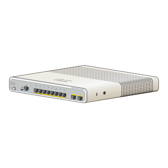
C H A P T E R Product Overview The Catalyst 3560-C and 2960-C of switches, also referred to as the switch, are Ethernet switches to which you can connect devices such as Cisco IP Phones, Cisco Wireless Access Points, workstations, and other network devices such as servers, routers, and other switches. -
Page 10: Front Panel
USB Type A port (available on the Catalyst 3560CPD-8PT-S, 2960CG-8TC-L, 3560CG-8PC-S, and • 3560CG-8TC-S switches) LEDs • All the 8-port and 12-port switches have similar components. See Figure 1-1, Figure 1-2, Figure 1-3, Figure 1-4, and Figure 1-5 for examples. Catalyst 3560-C and 2960-C Switch Hardware Installation Guide OL-23803-02... - Page 11 PO W ER O VE R ET H ER N ET Mode button LEDs USB Type A port 10/100/1000 PoE+ ports USB mini-Type B (console) port Dual-purpose ports RJ-45 console port Catalyst 3560-C and 2960-C Switch Hardware Installation Guide OL-23803-02...
- Page 12 Po E Po E CO NS OL PO W ER OV ER ET HE RN Mode button LEDs USB mini-Type B (console) port 10/100 PoE ports RJ-45 console port Dual-purpose ports Catalyst 3560-C and 2960-C Switch Hardware Installation Guide OL-23803-02...
-
Page 13: 10/100 And 10/100/1000 Fast Ethernet Downlink Ports
The PoE and PoE+ ports provide PoE support for devices compliant with 802.3af and 802.3at and also provide Cisco prestandard PoE and PoE+ support for Cisco IP Phones and Cisco Aironet Access Points. All 8 downlink ports on the Catalyst 2960CPD-8PT-L, 2960C-8PC-L, 2960C-12-PC-L, and the 3560CPD-8PT-S and are PoE-capable. -
Page 14: Poe Pass-Through
Category 6 unshielded twisted pair (UTP) cable. The 10BASE-T traffic can use Category 3 or Category 4 UTP cable. Cisco intelligent power management capabilities include enhanced power negotiation, power reservation, and per-port power policing. For information about configuring and monitoring PoE ports, see the switch software configuration guide on Cisco.com. - Page 15 IP phone receiving power from the PoE the PoE+ switch downlink port Catalyst 2960-C switch The available switch PoE budget depends upon the PoE sent from the uplink switch. See Table 1-2. Catalyst 3560-C and 2960-C Switch Hardware Installation Guide OL-23803-02...
-
Page 16: Poe Uplink Ports (Catalyst 2960Cpd-8Tt-L, 2960Cpd-8Pt-L, And 3560Cpd-8Pt-S)
– 22.4 W (30.8 1. The second UPOE uplink is a backup. 2. When the Auxiliary AC input is used as a backup to a Cisco UPOE powered switch. Table 1-3 PoE Budgeting for the Catalyst 3560CPD-8PT-S Switch Powering Options on the... -
Page 17: Poe-Capable Downlink Ports (Catalyst 2960Cpd-8Pt-L, 3560Cg-8Pc-S, 3560Cpd-8Pt-S, 2960C-8Pc-L, 2960C-12Pc-L, 3560C-8Pc-S, And 3560C-12Pc-S)
2-4. USB Type A Port Some models have an USB Type A port. This port provides access to external Cisco USB flash devices (also known as thumb drives or USB keys). The port supports Cisco USB flash drives with capacities from 64 MB to 1 GB. -
Page 18: Management Ports
The USB-mini console interface speeds are the same as the RJ-45 console interface speeds. To use the USB-mini console port, you must install the Cisco Windows USB device driver on the device that is connected to the USB-mini console port and that is running Microsoft Windows. -
Page 19: Leds
STAT LED (status) PD LED (powered device) DPLX LED (duplex) Port LEDs 1. Applicable to switches with PoE ports. 2. Only the Catalyst 2960CPD-8PT-L and 3560PD-8PT-S switches have the PD LED. Catalyst 3560-C and 2960-C Switch Hardware Installation Guide 1-11 OL-23803-02... -
Page 20: System Led
USB-mini console port is active. USB-mini console port Green USB-mini console port is active. RJ-45 console port LED is not active. Port is not active. RJ-45 console port is active. Catalyst 3560-C and 2960-C Switch Hardware Installation Guide 1-12 OL-23803-02... -
Page 21: Modes For Port Leds
Port is blocked by Spanning Tree Protocol (STP) and is not forwarding data. After a port is reconfigured, the port LED is amber for up to 30 seconds as STP searches for loops. Catalyst 3560-C and 2960-C Switch Hardware Installation Guide 1-13 OL-23803-02... -
Page 22: Poe Led
The ports can autonegotiate, or you can manually configure each dual-purpose port as either 10/100/1000 with copper connectors or as an SFP-module port, but not as both types at the same time. Table 1-7 for LED descriptions. Catalyst 3560-C and 2960-C Switch Hardware Installation Guide 1-14 OL-23803-02... -
Page 23: Rear Panel
Heat sink fins (Catalyst 3560CG-8PC-S, 2960C-8PC-L, 2960C-12PC-L, 3560C-8PC-S, and • 3560C-12PC-S switches) Figure 1-10 Catalyst 2960CPD-8PT-L Switch Rear Panel R E S E T A U X 53 , 1. 5A Security slot Power adapter connector Reset button Catalyst 3560-C and 2960-C Switch Hardware Installation Guide 1-15 OL-23803-02... -
Page 24: Internal Power Supply
You can power the switch through either the 10/100/1000 uplink ports or through an auxiliary power adapter. You can order the auxiliary power adapter (PWR-ADPT) with the switch, or you can order it (PWR-ADPT=) later from your Cisco representative. Figure 1-12... -
Page 25: Security Slots
Network Assistant is available at no cost and can be downloaded from this URL: http://www.cisco.com/en/US/products/ps5931/tsd_products_support_series_home.html For information on starting Network Assistant, see the Getting Started with Cisco Network Assistant guide on Cisco.com. See the switch release notes for information on CNA support. -
Page 26: Network Configurations
Cisco IOS CLI • The switch CLI is based on Cisco IOS software and supports desktop-switching features. You can configure and monitor the switch and switch cluster members from the CLI. You can access the CLI either by connecting your management station directly to the switch console port or by using Telnet from a remote management station. -
Page 27: Switch Installation
• Warnings These warnings are translated into several languages in the Regulatory Compliance and Safety Information for the Catalyst 3560-C and the 2960-C Switches guide. Warning Before working on equipment that is connected to power lines, remove jewelry (including rings, necklaces, and watches). -
Page 28: Preparing For Installation
Statement 1024 Warning Ultimate disposal of this product should be handled according to all national laws and regulations. Statement 1040 Catalyst 3560-C and 2960-C Switch Hardware Installation Guide OL-23803-02... -
Page 29: Installation Guidelines
(4 cm) of empty rack space above each switch. • Catalyst 3560CG-8PC-S, 2960C-8PC-L, 2960C-12PC-L, 3560C-8PC-S, and 3560C-12PC-S switches: Allow at least 1.75 in. (4 cm) clearance from the ends of the external heat sink fins. Catalyst 3560-C and 2960-C Switch Hardware Installation Guide OL-23803-02... -
Page 30: Equipment That You Supply
Drill with a #27 drill bit (0.144-inch [3.7 mm]) Box Contents The switch getting started guide on Cisco.com describes the box contents. If any item is missing or damaged, contact your Cisco representative or reseller for support. Powering the Switch Before installing the switch in a rack, on a desk, a shelf, or a wall, you should power on the switch and verify that it passes POST. -
Page 31: Verifying Switch Operation
If a switch fails POST, the System LED turns amber. POST failures are usually fatal. Call Cisco technical support representative if your switch fails POST. After a successful POST, unplug the power cord from the switch. Mount the switch in a rack on a desk or shelf, under a desk or shelf, or on a wall, as described in the “Mounting the Switch”... -
Page 32: On A Desk Or Shelf (Without Mounting Screws)
2-1. This ensures that the power cord faces the rear of the desk or shelf after the switch is installed. Wait before you attach the screw template to the desk or shelf. Note Catalyst 3560-C and 2960-C Switch Hardware Installation Guide OL-23803-02... - Page 33 Place the switch onto the mounting screws, and slide it forward until it locks in place. See Figure 2-2. Step 7 Warning To prevent airflow restriction, allow clearance around the ventilation openings to be at least: 3 in. (7.6 cm) Statement 1076 Catalyst 3560-C and 2960-C Switch Hardware Installation Guide OL-23803-02...
-
Page 34: Under The Desk- Or Shelf-Mounting
Peel the adhesive strip off the bottom of the screw template, and attach it to the underside of the desk or Step 3 shelf. Catalyst 3560-C and 2960-C Switch Hardware Installation Guide OL-23803-02... - Page 35 Place the switch upside down onto the mounting screws, and slide it forward until it locks in place. See Step 7 Figure 2-4. To prevent airflow restriction, allow clearance around the ventilation openings to be at least: Warning 3 in. (7.6 cm) Statement 1076 Catalyst 3560-C and 2960-C Switch Hardware Installation Guide OL-23803-02...
-
Page 36: Wall-Mounting
Do not wall-mount the switch with its front panel facing up. Following safety regulations, wall-mount Caution the switch with its front panel facing down or to the side to prevent airflow restriction and to provide easier access to the cables. Catalyst 3560-C and 2960-C Switch Hardware Installation Guide 2-10 OL-23803-02... - Page 37 Step 7 Figure 2-5 Location of the Mounting Holes on the Switch 1.77 in. (4.49 cm) 2.67 in. (6.78) 3.72 in. (9.44 cm) 2.46. in. (6.24) 3.62 in. (9.19 cm) Switch Catalyst 3560-C and 2960-C Switch Hardware Installation Guide 2-11 OL-23803-02...
- Page 38 T R Y Figure 2-7 Installing the Switch on a Wall Place the switch onto the mounting screws, and slide it down until it locks in place. See Figure 2-7. Step 8 Catalyst 3560-C and 2960-C Switch Hardware Installation Guide 2-12 OL-23803-02...
-
Page 39: With A Mounting Tray
Mounting the Switch With a Mounting Tray The mounting kit (part number CMP-MGNT-TRAY=) is optional. You can order it when you order your switch, or you can order it later from your Cisco representative. The mounting kit ships contents: •... - Page 40 STA T DP LX MO DE SP D Se rie s Po E CO NS OL PO WE R OVE R ET HE RN Switch Mounting tray Sliding direction Desk Catalyst 3560-C and 2960-C Switch Hardware Installation Guide 2-14 OL-23803-02...
-
Page 41: Mounting Tray With A Magnet
This example shows you how to mount the switch on a metal wall. You can use a similar procedure to mount the switch under a metal desk or on a metal desk. Catalyst 3560-C and 2960-C Switch Hardware Installation Guide 2-15... - Page 42 Number-10 Phillips pan-head screws Place one side of the magnet against the bottom of the mounting tray, as shown in Figure 2-13. Mount Step 3 the magnet and switch on a metal wall. Catalyst 3560-C and 2960-C Switch Hardware Installation Guide 2-16 OL-23803-02...
- Page 43 To prevent airflow restriction, allow clearance around the ventilation openings to be at least: 3 in. (7.6 cm) Statement 1076 After you mount the switch, see the “After Installing the Switch” section on page 2-31 for information about configuring the switch. Catalyst 3560-C and 2960-C Switch Hardware Installation Guide 2-17 OL-23803-02...
-
Page 44: In A Rack
SYS T STA T D PLX M O D E Se ri es P oE C O N SO PO W ER O VER ETH ER N ET Phillips flat-head screw Catalyst 3560-C and 2960-C Switch Hardware Installation Guide 2-18 OL-23803-02... - Page 45 O VER ETH ER N ET Phillips machine screws After you mount the switch, see the “After Installing the Switch” section on page 2-31 for information about the switch configuration. Catalyst 3560-C and 2960-C Switch Hardware Installation Guide 2-19 OL-23803-02...
-
Page 46: On A Din Rail
Mounting the Switch On a DIN Rail The DIN-mount kit (part number CMP-DIN-MNT=) is optional. You can order it when you order your switch, or you can order it later from your Cisco representative. The DIN-mount kit contains: • Two number-10 Phillips pan-head screws •... - Page 47 Position the switch directly in front of the DIN rail, making sure that the top of the DIN rail mount clip Step 1 hooks over the top of the DIN rail. See Figure 2-19. Catalyst 3560-C and 2960-C Switch Hardware Installation Guide 2-21 OL-23803-02...
- Page 48 Lift lightly on the bottom of the switch to ensure that it is firmly locked in place. After you install the switch, see the “After Installing the Switch” section on page 2-31 for information about the switch configuration. Catalyst 3560-C and 2960-C Switch Hardware Installation Guide 2-22 OL-23803-02...
- Page 49 Pull down on the DIN rail mount release tabs. As the clips release, lift the bottom of the switch. Step 2 Figure 2-20. Figure 2-20 Switch Removal Switch Catalyst 3560-C and 2960-C Switch Hardware Installation Guide 2-23 OL-23803-02...
-
Page 50: Installing A Cover For The Reset Button (Optional)
Figure 2-22 Reset Cover on the Catalyst 2960CG-8PC-S Switch R E S E T R E S E T E S E T E S E T Switch Reset button cover Catalyst 3560-C and 2960-C Switch Hardware Installation Guide 2-24 OL-23803-02... -
Page 51: Installing The Power Cord Retainer (Optional)
The power cord retainer part number (PWR-CLP=) is optional. You can order it when you order your switch, or you can order it later from your Cisco representative. Choose the sleeve size of the power cord retainer based on the thickness of the cord. The smaller sleeve Step 1 can be snapped off and used for thin cords. - Page 52 (Optional) Use the small sleeve for thin power cords. Use the small sleeve to provide greater stability for Step 5 thin cords. Detach the sleeve, and slide it over the power cord. See Figure 2-26. Catalyst 3560-C and 2960-C Switch Hardware Installation Guide 2-26 OL-23803-02...
- Page 53 Sleeve for thin power cords AC power cord Step 6 Secure the AC power cord by pressing on the retainer. See Figure 2-27. Figure 2-27 Securing the Power Cord in the Retainer Catalyst 3560-C and 2960-C Switch Hardware Installation Guide 2-27 OL-23803-02...
-
Page 54: Installing The Cable Guard (Optional)
Installing the Cable Guard (Optional) The cable guard prevents tampering with the cables after the cables are installed. The cable guard (CMP-CBLE-GRD=) is not included with the switch, but you can order it from your Cisco representative. You can use the cable guard when the switch is mounted on a desk, under a desk, or on a wall. - Page 55 Ca ta lys t 29 60 -C Se rie s CO NS OL Cable guard Pivot direction for cable guard pivots Attach the cables to the switch. See Figure 2-31. Catalyst 3560-C and 2960-C Switch Hardware Installation Guide 2-29 OL-23803-02...
- Page 56 Guide the connected cables through the slots in the front of the cable guard. Slide the cable guide in as Step 4 shown in Figure 2-33. Tighten the screws. Figure 2-32 Guiding the Cables through the Guard Catalyst 3560-C and 2960-C Switch Hardware Installation Guide 2-30 OL-23803-02...
-
Page 57: After Installing The Switch
• module more often than is absolutely necessary. To prevent ESD damage, follow your normal board and component handling procedures when • connecting cables to the switch and other devices. Catalyst 3560-C and 2960-C Switch Hardware Installation Guide 2-31 OL-23803-02... -
Page 58: Removing Sfp Modules
Step 5 Grasp the SFP module, and carefully remove it from the slot. Place the module in an antistatic bag or other protective environment. Step 6 Catalyst 3560-C and 2960-C Switch Hardware Installation Guide 2-32 OL-23803-02... -
Page 59: Connecting Devices To The Ethernet Ports
See the switch software configuration guide or the switch command reference on Cisco.com for more information about autonegotiation and auto-MDIX. -
Page 60: Connecting To The Poe Ports
The ports provide PoE support for 802.3af-compliant devices and also provide Cisco prestandard PoE support for Cisco IP Phones and Cisco Aironet Access Points. On a per-port basis, you can control whether or not a port automatically provides power to a connected IP phone or an access point. -
Page 61: Management Options
Where to Go Next To change the switch settings, you can use the switch default configuration or use any of the management options described in the “Management Options”section. Catalyst 3560-C and 2960-C Switch Hardware Installation Guide 2-35 OL-23803-02... - Page 62 Chapter 2 Switch Installation Where to Go Next Catalyst 3560-C and 2960-C Switch Hardware Installation Guide 2-36 OL-23803-02...
-
Page 63: Chapter 3 Troubleshooting
You can also get statistics from the device manager, the CLI, or an SNMP workstation. See the software configuration guide, the switch command reference guide on Cisco.com, or the documentation that came with your SNMP application for details. Switch POST Results See the “Verifying Switch Operation”... -
Page 64: Switch Leds
Appendix B, “Connector and Cable • Specifications” for information. Look for loose connections. Sometimes a cable appears to be seated but is not. Disconnect the cable, • and then reconnect it. Catalyst 3560-C and 2960-C Switch Hardware Installation Guide OL-23803-02... -
Page 65: 10/100 And 10/100/1000 Port Connections
Cisco prestandard IP Phones, and wireless access points, or 802.3af-compliant devices. SFP Module Use only Cisco SFP modules. Each Cisco module has an internal serial EEPROM that is encoded with security information. This encoding verifies that the module meets the requirements for the switch. -
Page 66: Spanning Tree Loops
If the port statistics show excessive FCS, late-collision, or alignment errors, verify that the cable distance from the switch to the connected device meets the recommended guidelines. See the “Cables and Adapters” section on page B-3. Catalyst 3560-C and 2960-C Switch Hardware Installation Guide OL-23803-02... -
Page 67: Resetting The Switch
Alternatively, you can press the Reset button on the rear of the switch to power cycle the switch. Finding the Switch Serial Number If you contact Cisco Technical Assistance, you need to know the switch serial number. Figure 3-1 Figure 3-2 show the serial number locations. - Page 68 Finding the Switch Serial Number Figure 3-2 Serial Number Location for the Catalyst 3560CG-8PC-S, 3560CG-8PC-S, and the 3560CG-8TC-S SN: XXXNNNNXXXX Figure 3-3 Serial Number Location for the Catalyst 3560CPD-8PT-S Switch SN: XXXNNNNXXXX Catalyst 3560-C and 2960-C Switch Hardware Installation Guide OL-23803-02...
- Page 69 Chapter 3 Troubleshooting Finding the Switch Serial Number Figure 3-4 Serial Number Location for the Catalyst 2960C-8TC-L, 2960C-8TC-S, 2960C-8PC-L, 2960C-12PC-L, 3560C-8PC-S, and 3560C-12PC-S Switches SN: XXXNNNNXXXX Catalyst 3560-C and 2960-C Switch Hardware Installation Guide OL-23803-02...
- Page 70 Chapter 3 Troubleshooting Finding the Switch Serial Number Catalyst 3560-C and 2960-C Switch Hardware Installation Guide OL-23803-02...
-
Page 71: Appendix
A P P E N D I X Technical Specifications Table A-1 Environmental and Physical Specifications for the Catalyst 3560-C and 2960-C Switches Environmental Ranges Operating temperature Catalyst 2960CPD-8TT-L 23 to 113°F (–5 to 45°C) up to 5000 ft (1524 m) - Page 72 Appendix A Technical Specifications Table A-1 Environmental and Physical Specifications for the Catalyst 3560-C and 2960-C Switches Environmental Ranges Physical Specifications Weight Catalyst 2960CPD-8TT-L 2.4 lb (1.08 kg) Catalyst 2960CPD-8PT-L 2.4 lb (1.08 kg) Catalyst 2960CG-8TC-L 3.0 lb (1.35 kg) Catalyst 2960C-8TC-L 2.8 lb (1.27 kg)
- Page 73 Catalyst 2960CPD-8TT-L: 37 to 57 VDC, 0.01 to 0.3 A • Catalyst 2960CPD-8PT-L: 37 to 57 VDC, 0.01 to 0.6 A Catalyst 3560CPD-8PT-S: 37 to 57 VDC, 0.01 to 0.6 A • Catalyst 3560-C and 2960-C Switch Hardware Installation Guide OL-23803-02...
- Page 74 Catalyst 3560CPD-8PT-S: 0.05 KVA • Catalyst 3560C-8PC-S: 0.16 KVA • Catalyst 3560C-12PC-S: 0.16 KVA • 1. BTU values are switch dissipation only (excludes PoE which is dissipated at the end device). Catalyst 3560-C and 2960-C Switch Hardware Installation Guide OL-23803-02...
- Page 75 19.1 W 159 W 123.2 W 1. Requires both the uplink ports to be connected to PoE+ inputs. 2. Reguires the uplink port to be connected to Cisco UPOE switch input. Catalyst 3560-C and 2960-C Switch Hardware Installation Guide OL-23803-02...
- Page 76 Appendix A Technical Specifications Catalyst 3560-C and 2960-C Switch Hardware Installation Guide OL-23803-02...
-
Page 77: Appendix
The 10/100 and 10/100/1000 Ethernet ports on switches use RJ-45 connectors and Ethernet pinouts with internal crossovers. Figure B-1 Figure B-2 show the pinouts. Figure B-1 10/100 Port Pinouts Label 4 5 6 7 8 Catalyst 3560-C and 2960-C Switch Hardware Installation Guide OL-23803-02... -
Page 78: Sfp Module Connectors
Dual-Purpose Ports The 10/100/1000 Ethernet ports on the dual-purpose ports use RJ-45 connectors. Figure B-4 10/100/1000 Port Pinouts Label 4 5 6 7 8 TP0+ TP0- TP1+ TP2+ TP2- TP1- TP3+ TP3- Catalyst 3560-C and 2960-C Switch Hardware Installation Guide OL-23803-02... -
Page 79: Cables And Adapters
SFP module and the MMF cable on both the sending and receiving ends of the link. The mode-conditioning patch cord is required for link distances greater than 984 feet (300 m). Catalyst 3560-C and 2960-C Switch Hardware Installation Guide OL-23803-02... -
Page 80: Cable Pinouts
1 TP0+ 1 TP0+ 2 TP0- 2 TP0- 3 TP1+ 3 TP1+ 6 TP1- 6 TP1- 4 TP2+ 4 TP2+ 5 TP2- 5 TP2- 7 TP3+ 7 TP3+ 8 TP3- 8 TP3- Catalyst 3560-C and 2960-C Switch Hardware Installation Guide OL-23803-02... -
Page 81: Console Port Adapter Pinouts
RJ-45-to-DB-9 adapter cable, and the console device. Table B-2 Console Port Signaling Using a DB-9 Adapter Switch Console RJ-45-to-DB-9 Console Port (DTE) Terminal Adapter Device Signal DB-9 Pin Signal Catalyst 3560-C and 2960-C Switch Hardware Installation Guide OL-23803-02... - Page 82 The RJ-45-to-DB-25 female DTE adapter is not supplied with the switch. You can order this adapter from Note Cisco (part number ACS-DSBUASYN=). Table B-3 Console Port Signaling Using a DB-25 Adapter Switch Console RJ-45-to-DB-25 Console Port (DTE) Adapter Device Signal DB-25 Pin Signal Catalyst 3560-C and 2960-C Switch Hardware Installation Guide OL-23803-02...
-
Page 83: Appendix
This appendix provides a command-line interface (CLI) setup procedure for a standalone switch. To set up the switch by using Express Setup, see the Catalyst 3560-C and 2960-C Switch Getting Started Guide. Before connecting the switch to a power source, review the safety warnings in Chapter 2, “Switch... - Page 84 Step 4 The PC or terminal displays the bootloader sequence. Press Enter to display the setup prompt. Follow Step 5 the steps in the “Completing the Setup Program” section on page C-7. Catalyst 3560-C and 2960-C Switch Hardware Installation Guide OL-23803-02...
-
Page 85: Usb Mini-Type B Console Port
Choose Start > Control Panel > Systems. Click the Hardware tab and choose Device Manager. Expand the Ports section. The assigned COM port appears in parenthesis at the end of the line with this entry: Cisco USB System Management Console. -
Page 86: Installing The Cisco Microsoft Windows Usb Device Drivers
Obtain the file Cisco_usbconsole_driver.zip from Cisco.com, and unzip it. Step 1 You can download the driver file from the Cisco.com software download site. Note If using 32-bit Windows XP, double-click the setup.exe file in the Windows_32 folder. If using 64-bit Step 2 Windows XP, double-click the setup(x64).exe file in the Windows_64 folder. -
Page 87: Installing The Cisco Microsoft Windows 2000 Usb Driver
Accessing the CLI Through the Console Port Installing the Cisco Microsoft Windows 2000 USB Driver Obtain the file Cisco_usbconsole_driver.zip from Cisco.com, and unzip it. Step 1 You can download the driver file from the Cisco.com software download site. Note Double-click the setup.exe file. Step 2 The Cisco Virtual Com InstallShield Wizard begins. -
Page 88: Uninstalling The Cisco Microsoft Windows Usb Drivers
Step 4 When the InstallShield Wizard Completed window appears, click Finish. Step 5 Uninstalling the Cisco Microsoft Windows Vista and Windows 7 USB Driver Disconnect the switch console terminal before uninstalling the driver. Note Run setup.exe for 32-bit Windows or setup(x64).exe for 64-bit Windows. Click Next. -
Page 89: Entering The Initial Configuration Information
On a command switch, the host name is limited to 28 characters and on a member switch to 31 characters. Do not use -n, where n is a number, as the last character in a host name for any switch. Enter host name [Switch]: host_name Catalyst 3560-C and 2960-C Switch Hardware Installation Guide OL-23803-02... - Page 90 The following configuration command script was created: hostname switch1 enable secret 5 $1$Ulq8$DlA/OiaEbl90WcBPd9cOn1 enable password enable_password line vty 0 15 password terminal-password no snmp-server no ip routing interface Vlan1 no shutdown ip address 10.4.120.106 255.0.0.0 interface FastEthernet1/0/1 Catalyst 3560-C and 2960-C Switch Hardware Installation Guide OL-23803-02...
- Page 91 After you complete the setup program, the switch can run the default configuration that you created. To change this configuration or to perform other management tasks, enter commands at the Switch> prompt Catalyst 3560-C and 2960-C Switch Hardware Installation Guide OL-23803-02...
- Page 92 Appendix C Configuring the Switch with the CLI Setup Program Entering the Initial Configuration Information Catalyst 3560-C and 2960-C Switch Hardware Installation Guide C-10 OL-23803-02...