Acer Aspire one Series Service Manual
(ao751h)
Hide thumbs
Also See for Aspire one Series:
- User manual (1960 pages) ,
- Generic user manual (1454 pages) ,
- Quick manual (319 pages)

Related Manuals for Acer Aspire one Series


Summary of Contents for Acer Aspire one Series
-
Page 1: Aspire One Series
Aspire one (AO751h)Series Service Guide Service guide files and updates are available on the ACER/CSD web; for more information, please refer to http://csd.acer.com.tw PRINTED IN TAIWAN... -
Page 2: Revision History
Revision History Please refer to the table below for the updates made on this service guide. Date Chapter Updates... - Page 3 Copyright Copyright © 2009 by Acer Incorporated. All rights reserved. No part of this publication may be reproduced, transmitted, transcribed, stored in a retrieval system, or translated into any language or computer language, in any form or by any means, electronic, mechanical, magnetic, optical, chemical, manual or otherwise, without the prior written permission of Acer Incorporated.
- Page 4 Conventions The following conventions are used in this manual: Denotes actual messages that appear SCREEN MESSAGES on screen. NOTE Gives bits and pieces of additional information related to the current topic. WARNING Alerts you to any damage that might result from doing or not doing specific actions.
- Page 5 DIFFERENT part number code to those given in the FRU list of this printed Service Guide. You MUST use the list provided by your regional Acer office to order FRU parts for repair and service of customer machines.
-
Page 7: Table Of Contents
Your Acer Notebook tour ........ - Page 8 Table of Contents Removing the CRT Board ......... .66 Removing the LAN Board .
- Page 9 Aspire one Series ........
- Page 10 Table of Contents...
-
Page 11: System Specifications
Supports 512 MB / 1 GB soDIMMs for total system memory of up to 1 GB Display and graphics • 11.6" HD WXGA high-brightness (typical 200-nit) Acer CrystalBrite™ TFT LCD, 1366 x 768 pixel resolution Storage subsystem •... -
Page 12: Privacy Control
• WWAN: UMTS/HSPA at 850/1900/2100 MHz and quad-band GSM/GPRS/EDGE (850/900/1800/ 1900 MHz) (for 3G models) Privacy control • Kensington lock slot Dimensions and Weight • 284 (W) x 198 (D) x 25.4 (H) mm (11.18 x 7.79 x 1 inches) •... -
Page 13: System Block Diagram
System Block Diagram CPU FSB (133MHz) PCB STACK UP SCH FSB (133MHz) SCH PCIE (100MHz) LAYER 1 : TOP SCH DA (96MHz) LAYER 2 : GND CLOCK GEN CK505 SCH DB (100MHz) (ICS9LPRS365BKLFT) Intel@Atom(Silverthorne) LAYER 3 : IN1 SCH CLK14 (14.31818MHz) Z520/Z530 LAYER 4 : IN2 14 x 13 mm 441 Balls... -
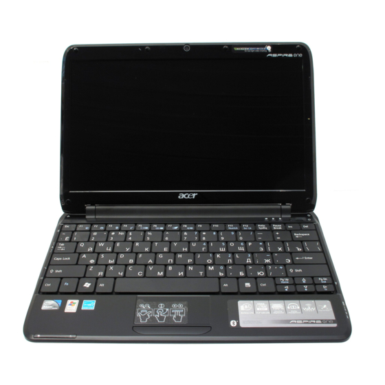
Page 14: Your Acer Notebook Tour
Your Acer Notebook tour After learning about your computer features, let us show you around your new computer. Front View Icon Item Description Acer Crystal Eye Web camera for video communication. Webcam Microphone Internal microphone for sound recording. Display screen Also called Liquid-Crystal Display (LCD), displays computer output. -
Page 15: Closed Front View
Icon Item Description Status indicators Light-Emitting Diodes (LEDs) that light up to show the status of the computer's functions and components. Power button/ Turns the computer on and off while indicating the indicator computer’s power status. Closed Front View Icon Item Description Bluetooth... -
Page 16: Right View
Right View Icon Item Description Multi-in-1 card Accepts Secure Digital (SD), MultiMediaCard reader (MMC), Memory Stick (MS), Memory Stick PRO (MS PRO), xD-Picture Card (xD). Note: Push to remove/install the card. Only one card can operate at any given time. USB 2.0 port Connects to USB 2.0 devices (e.g. -
Page 17: Rear And Base View
Rear and Base View Icon Item Description 3G SIM card slot Accepts a 3G SIM card for 3G connectivity. Note: Insert a 3G SIM card to enable 3G communication. The SIM card connectors need to face away from the cover. (only for certain models). Battery bay Houses the computer's battery pack. -
Page 18: Indicators
Indicators The computer has several easy-to-read status indicators. The battery indicator is visible even when the computer cover is closed. Icon Function Description Bluetooth Indicates the status of Bluetooth communication. Wireless LAN Indicates the status of Wireless LAN communication. 3G communication Indicates the status of 3G communication. -
Page 19: Touchpad Basics
TouchPad Basics The following items show you how to use the TouchPad: • Move your finger across the TouchPad (1) to move the cursor. • Press the left (2) and right (3) buttons located beneath the TouchPad to perform selection and execution functions. -
Page 20: Using The Keyboard
Using the Keyboard Your Aspire one has a close-to-full-sized keyboard and an embedded numeric keypad, separate cursor, lock, function and special keys. Lock Keys and embedded numeric keypad The keyboard has three lock keys which you can toggle on and off. Lock key Description Caps Lock... -
Page 21: Windows Keys
Windows Keys The keyboard has two keys that perform Windows-specific functions. Description Windows key Pressed alone, this key has the same effect as clicking on the Windows Start button; it launches the Start menu. It can also be used with other keys to provide a variety of functions: : Open or close the Start menu <... -
Page 22: Hot Keys
Hot Keys The computer employs hotkeys or key combinations to access most of the computer's controls like screen brightness and volume output. To activate hotkeys, press and hold the <Fn> key before pressing the other key in the hotkey combination. Hotkey Icon Function... -
Page 23: Special Keys
Special Keys You can locate the Euro symbol and the US dollar sign at the upper-center and/or bottom-right of your keyboard. The Euro symbol Open a text editor or word processor. Hold <Alt Gr> and then press the <5> key at the upper-center of the keyboard. NOTE: Some fonts and software do not support the Euro symbol. -
Page 24: Hardware Specifications And Configurations
Mobile Intel® US15W Express Chipset Features • Hyper-Threading Technology • Intel® Virtualization Technology • Execute Disable Bit Processor Specifications Cache Core Item Cores Package Acer P/N Speed Speed Tech Size Voltage Z520 1.33 GHz 533 MHz 45 nm Micro- 0.75- FCBGA 1.1V Z530 1.6 GHz... - Page 25 System Memory Item Specification Memory controller Intel Poulsbo AF82US15W Memory size DIMM socket number Supports memory size per socket Supports maximum memory size Supports DIMM type DDR2 Supports DIMM Speed 667MHz/533MHz Hard Disk Drive Interface Item Specification Vendor & Seagate Seagate Hitachi Hitachi...
- Page 26 LED 11.6” Item Specifications Vendor/model name Samsung B11.6XW02 N116B6-L02 LP116WH1- LTN116AT01- TLA1 Screen Diagonal (mm) 11.6” 11.6” 11.6” 11.6” Active Area (mm) 256.125 x 256.125 x 144 256.13 x 144 256.125 x 144 Display resolution (pixels) 1366 x 768 1366 x 768 1366 x 768 1366 x 768 Pixel Pitch (mm)
- Page 27 Audio Codec and Amplifier Item Specification Audio Realtek ALC272 Azalia Codec and Amplifier G1454 Controller Features • HD Audio • SNR > 85,High-performance DACs with 95dB SNR (A-Weighting), ADCs with 85dB SNR (A-Weighting) • Internal Digital Microphone • Two speakers, max. 1W output for each •...
- Page 28 LAN Interface Item Specification LAN Chipset Realtek RTL8103A-GR Package 48pin-LQFP package Features • Integrated 10/100 BASE -T transceiver • PCIe V1.1 compliant supports • Wake on LAN and remote wake-up support Modem Item Specification Modem Module D-1156U#/A9B soft modem Package 20-pin TSSOP package Features •...
- Page 29 Keyboard Item Specification Type New Acer flat keyboard Total number of keypads 86/87/91 Windows logo key Internal & external keyboard work simultaneously Features • Support Application keys for Windows XP version Mini Card Item Specification Number Supported Features • 1 for 3G/ WiMAX (full size) •...
- Page 30 Item Specification Channel Numbers • 1---11 channels for active channels • 12---13 channels for passive channels Data Rate 54Mbps with fall back rates of 48, 36, 24, 18, 12, 9 and 6Mbps Media Access Protocol CSMA/CA with ACK Transmitter Output Power Typical 13.5 dBm for 54Mbps 802.11b Radio Technology...
-
Page 31: System Utilities
Chapter 2 System Utilities BIOS Setup Utility The BIOS Setup Utility is a hardware configuration program built into your computer’s BIOS (Basic Input/ Output System). Your computer is already properly configured and optimized, and you do not need to run this utility. However, if you encounter configuration problems, you may need to run Setup. -
Page 32: Information
Information The Information screen displays a summary of your computer hardware information. P h o e n i x S e c u r e C o r e ( t m ) S e t u p U t i l i t y Information Main Intel... -
Page 33: Main
Main The Main screen allows the user to set the system time and date as well as enable and disable boot option and recovery. P h o e n i x S e c u r e C o r e ( t m ) S e t u p U t i l i t y Information Main Intel... -
Page 34: Intel
Intel The Intel screen allows the user to control various CPU and graphics processor parameters. P h o e n i x S e c u r e C o r e ( t m ) S e t u p U t i l i t y Information Main Intel... - Page 35 Parameter Description Format/Option Poulsbo Control Enter the Poulsbo control menu. • PCI Express Control Sub-Menu Sub-Menu • Poulsbo USB Control Sub-Menu • Azalia - Device 27, Function 0: • SDIO - Device 30, Function 0/1/2: • PCI Clock Run: • Serial IRQ Quiet Mode: •...
-
Page 36: Security
Security The Security screen contains parameters that help safeguard and protect your computer from unauthorized use. P h o e n i x S e c u r e C o r e ( t m ) S e t u p U t i l i t y Information Main Intel... -
Page 37: Setting A Password
Setting a Password Follow these steps as you set the user or the supervisor password: Use the ↑ and ↓ keys to highlight the Set Supervisor Password parameter and press the Enter key. The Set Supervisor Password box appears: S e t S u p e r v i s o r P a s s w o r d E n t e r N e w P a s s w o r d C o n f i r m N e w P a s s w o r d Type a password in the “Enter New Password”... -
Page 38: Changing A Password
Changing a Password Use the ↑ and ↓ keys to highlight the Set Supervisor Password parameter and press the Enter key. The Set Password box appears. S e t S u p e r v i s o r P a s s w o r d E n t e r C u r r e n t P a s s w o r d E n t e r N e w P a s s w o r d C o n f i r m N e w P a s s w o r d... -
Page 39: Boot
Boot This menu allows the user to decide the order of boot devices to load the operating system. Bootable devices includes the USB diskette drives, the onboard hard disk drive and the DVD drive in the module bay. P h o e n i x S e c u r e C o r e ( t m ) S e t u p U t i l i t y Information Main Security... -
Page 40: Exit
Exit The Exit screen allows you to save or discard any changes you made and quit the BIOS Utility. P h o e n i x S e c u r e C o r e ( t m ) S e t u p U t i l i t y Information Main Security... -
Page 41: Bios Flash Utility
BIOS Flash Utility The BIOS flash memory update is required for the following conditions: • New versions of system programs • New features or options • Restore a BIOS when it becomes corrupted. Use the Phlash utility to update the system BIOS flash ROM. NOTE: If you do not have a crisis recovery diskette at hand, then you should create a Crisis Recovery Diskette before you use the Phlash utility. - Page 42 The flash process begins as shown. In flash BIOS, the message Please do not remove AC Power Source displays. Chapter 2...
- Page 43 NOTE: If the AC power is not connected, the following message displays. Plug in the AC power to continue. Flash is complete when the message Flash programming complete displays. Chapter 2...
-
Page 44: Winflash Utility
WinFlash Utility Perform the following steps to use the WinFlash Utility: Double click the WinFlash executable. Click OK to begin the update. A progress screen displays. When the process is complete, close all programs and applications and reboot the system. Chapter 2... -
Page 45: Remove Hdd/Bios Password Utilities
Remove HDD/BIOS Password Utilities This section provides you with details about removing HDD/BIOS password methods: Removing HDD Password: If you key in the wrong HDD password three times, an error code is generated. To reset the HDD password, perform the following steps: On a different machine, run the HDD_PW.EXE file along with the error code generated. - Page 46 Removing BIOS Passwords: If you key in the wrong Supervisor password three times, an error code is generated and system is disabled. To unlock the BIOS, perform the following steps: On a different machine, run the BIOS_PW.EXE file along with the error code generated. For example: bios_pw 14452 0 Four ASCII strings are generated as output.
-
Page 47: Miscellaneous Utilities
Miscellaneous Utilities Using Boot Sequence Selector Boot Sequence Selector allows the boot order to be changes without accessing the BIOS. To use Boot Sequence Selector, perform the following steps: Enter into DOS. Execute BS.exe to display the usage screen. Select the desired boot sequence by entering the corresponding sequence, for example, enter BS2 to change the boot sequence to HDD|CD ROM|LAN|Floppy. - Page 48 Manufacturer (Type1, Offset04h): Acer Product Name (Type1, Offset05h): Aspire one xxxxx Serial Number (Type1, Offset07h): 01234567890123456789 UUID String (Type1, Offset08h): xxxxxxxx-xxxx-xxxx-xxxx-xxxxxxxxxxxx Asset Tag (Type3, Offset04h): Acer Asstag Example 2: Write Product Name to EEPROM Input: dmitools /wp Acer Example 3: Write Serial Number to EEPROM...
- Page 49 Chapter 2...
- Page 50 Chapter 2...
-
Page 51: Machine Disassembly And Replacement
Chapter 3 Machine Disassembly and Replacement This chapter contains step-by-step procedures on how to disassemble the notebook computer for maintenance and troubleshooting. Disassembly Requirements To disassemble the computer, you need the following tools: Wrist grounding strap and conductive mat for preventing electrostatic discharge •... -
Page 52: General Information
General Information Pre-disassembly Instructions Before proceeding with the disassembly procedure, make sure that you do the following: 1. Turn off the power to the system and all peripherals. 2. Unplug the AC adapter and all power and signal cables from the system. 3. -
Page 53: External Module Disassembly Process
External Module Disassembly Process NOTE: The product previews seen in the disassembly procedures may not represent the final product color or configuration. External Modules Disassembly Flowchart Turn off system and peripherals power Disconnect power and signal cables from system Remove Battery Remove Lower Covers... -
Page 54: Removing The Battery Pack
Removing the Battery Pack 1. Turn the computer over. 2. Slide the battery lock/unlock latch to the unlock position. 3. Slide and hold the battery release latch to the release position (1), then slide out the battery pack from the main unit (2). -
Page 55: Removing The Lower Covers
Removing the Lower Covers 1. See “Removing the Battery Pack” on page 44. 2. Loosen the six captive screws in the HDD, Memory, and 3G Covers. 3. Lift the HDD cover up to remove. Chapter 3... - Page 56 4. Lift the Memory cover up to remove. 5. Lift the 3G cover up to remove. Chapter 3...
-
Page 57: Removing The Hard Disk Drive Module
Removing the Hard Disk Drive Module 1. See “Removing the Lower Covers” on page 45. 2. Remove the single screw securing the HDD Module in place. 3. Slide the HDD in the direction of the arrow to disconnect the HDD from the interface connector. 4. - Page 58 5. Remove the four screws (two each side) securing the hard disk to the carrier. Step Size Quantity Screw Type HDD Carrier M3*3 6. Remove the HDD from the carrier. Chapter 3...
-
Page 59: Removing The Dimm Module
Removing the DIMM Module 1. See “Removing the Lower Covers” on page 45. 2. Push out the release latches on both sides of the DIMM socket to release the DIMM module. 3. Remove the DIMM module. Chapter 3... -
Page 60: Removing The Wlan Board
Removing the WLAN Board 1. See “Removing the Lower Covers” on page 45. 2. Disconnect the Antenna cables from the WLAN Board. NOTE: Cable placement is Black to the MAIN terminal (right) and White to the AUX terminal (left). 3. Remove the single screw securing the WLAN Board in place. Step Size Quantity... - Page 61 4. Remove the WLAN Board from the Mainboard. Chapter 3...
-
Page 62: Removing The 3G Module
Removing the 3G Module IMPORTANT: 3G functionality is not supported by all models. 1. See “Removing the Lower Covers” on page 45. 2. Disconnect the 3G Antenna cables from the 3G Module. IMPORTANT: The Blue cable attaches to the MAIN terminal (left) and the Yellow cable attaches to the AUX terminal (right). - Page 63 4. Detach the 3G Module from the socket. NOTE: When reattaching the antennas, ensure the cables are tucked into the chassis to prevent damage. Chapter 3...
-
Page 64: Main Unit Disassembly Process
Main Unit Disassembly Process IMPORTANT: Cable paths and positioning may not represent the actual model. During the removal and replacement of components, ensure all available cable channels and clips are used and that the cables are replaced in the same position. NOTE: The product previews seen in the disassembly procedures may not represent the final product color or configuration. -
Page 65: Removing The Keyboard
Removing the Keyboard 1. See “Removing the Battery Pack” on page 44. 2. Turn the computer rightside up and open the lid to the full extent. 3. Unlock the four securing latches by pressing down with a suitable plastic tool. IMPORTANT: The use of metal tools may damage the outer casing. - Page 66 6. Disconnect the FFC and remove the Keyboard. Chapter 3...
-
Page 67: Removing The Hinge Covers
Removing the Hinge Covers 1. See “Removing the Battery Pack” on page 44. 2. Turn the computer over. Remove the four screws securing the Hinge Covers to the Lower Cover. Step Size Quantity Screw Type Hinge Covers M2*5 3. Lift the Hinge Covers away from the Upper Cover as shown. Chapter 3... -
Page 68: Removing The Upper Cover
Removing the Upper Cover 1. See “Removing the Keyboard” on page 55. 2. Remove the ten screws securing the Upper Cover to the Lower Cover. Step Size Quantity Screw Type Upper Cover M2*5 (red callouts) Upper Cover M2*3 (green callouts) 3. - Page 69 Release the locking latch as shown. Disconnect the FFC as shown. 4. Remove the eleven securing screws from the Upper Cover. Step Size Quantity Screw Type Upper Cover M2*5 (red callout) Upper Cover M2*2.5 (green callout) Chapter 3...
- Page 70 5. Starting at the front the cover, pry apart the Upper and Lower Covers as shown. 6. Working along the front to the left and right, pry apart the covers as shown. 7. Lift the Upper Cover clear of the Lower Cover. Chapter 3...
-
Page 71: Removing The Touchpad Bracket And Button Board
Removing the TouchPad Bracket and Button Board IMPORTANT: The TouchPad Board cannot be removed individually. To replace the TouchPad Board, replace the entire Upper Cover. 1. See “Removing the Upper Cover” on page 58. 2. Open the locking latches and disconnect the two FFCs from the Button Board as shown. 3. - Page 72 IMPORTANT: Ensure that the FFCs are disconnected before attempting to remove the TouchPad Bracket. 4. Lift the TouchPad Bracket away from the Upper Cover as shown. 5. Turn the TouchPad Bracket over and remove the Button Board from the bracket. 6.
- Page 73 7. Open the FFC locking latch and disconnect the FFC from the TouchPad connector. 8. Turn the Upper Cover over and push the FFC through the cover as shown. 9. Turn the Upper Cover over and pull the FFC through the cover as shown. IMPORTANT: Ensure that the FFC pull tab is not torn off during removal.
-
Page 74: Removing The Card Reader Board
Removing the Card Reader Board 1. See “Removing the Upper Cover” on page 58. 2. Open the locking latch and disconnect the FFC from the Card Reader Board. 3. Open the locking latch and disconnect the FFC from the Mainboard. Chapter 3... - Page 75 4. Remove the single screw securing the Card Reader Board to the Lower Cover. Step Size Quantity Screw Type Card Reader M2*5 Board 5. Remove the board from the Lower Cover, left side first to release the I/O ports. Chapter 3...
-
Page 76: Removing The Crt Board
Removing the CRT Board 1. See “Removing the Upper Cover” on page 58. 2. Remove the single screw securing the CRT Board to the Lower Cover. Step Size Quantity Screw Type CRT Board M2*5 3. Lift the CRT Board left side first and turn it over to expose the CRT cable. IMPORTANT: Do not remove the board from the Lower Cover;... - Page 77 4. Disconnect the cable from the CRT Board and remove the board from the Lower Cover. Chapter 3...
-
Page 78: Removing The Lan Board
Removing the LAN Board 1. See “Removing the Upper Cover” on page 58. 2. Lift the adhesive strip securing the LVDS cable in place and disconnect the cable from the Mainboard. 3. Disconnect the FFC cable from the LAN Board by pulling on the cable tab as shown. NOTE: This FFC connector does not use a cable latch to secure the FFC in place. - Page 79 5. Remove the single screw securing the LAN Board to the Lower Cover. Step Size Quantity Screw Type LAN Board M2*5 6. Push the RJ-45 connector through the Lower Cover as shown and remove the LAN Board from the computer. Chapter 3...
-
Page 80: Removing The Lcd Module
Removing the LCD Module 1. See “Removing the CRT Board” on page 66. NOTE: It is not necessary to remove the LAN Board before removing the LCD Module. 2. Lift the adhesive strip securing the LVDS cable in place and disconnect the cable from the Mainboard. 3. - Page 81 4. Remove the two screws on the rear of the Lower Cover securing the LCD Module to the computer. Step Size Quantity Screw Type LCD Module M2*3 5. Remove the three screws (two on the left hinge and one on the right) securing the LCD Module to the Lower Cover.
- Page 82 IMPORTANT: Ensure that the LCD cables are free from all cable clips before removing the LCD Module. 6. Using both hands, lift the LCD Module away from the Lower Cover. Chapter 3...
-
Page 83: Removing The Bluetooth Module
Removing the Bluetooth Module 1. See “Removing the Upper Cover” on page 58. 2. Disconnect the Bluetooth cable from the Mainboard. 3. Lift the adhesive strip to detach the cable from the Lower Cover. 4. Disconnect the cable from the Bluetooth Module. Chapter 3... - Page 84 5. Lift the Bluetooth Module, left side first, to remove it from the Lower Cover. Chapter 3...
-
Page 85: Removing The Led Board
Removing the LED Board 1. See “Removing the Upper Cover” on page 58. 2. Open the locking latch and disconnect the LED Board FFC from the Mainboard. 3. Open the locking latch and disconnect the FFC from the LED Board. Chapter 3... - Page 86 4. Remove the single screw securing the LED Board to the Lower Cover. Step Size Quantity Screw Type LED Board M2*5 5. Lift the LED Board from the Lower Cover. Chapter 3...
-
Page 87: Removing The Cpu Fan
Removing the CPU Fan 1. See “Removing the LED Board” on page 75. 2. Disconnect the fan power cable from the Mainboard. 3. Remove the three screws securing the CPU Fan to the Lower Cover. Step Size Quantity Screw Type CPU Fan M2*3 Chapter 3... - Page 88 4. Lift the CPU Fan clear of the Lower Cover. Chapter 3...
-
Page 89: Removing The Speaker Module
Removing the Speaker Module 1. See “Removing the CPU Fan” on page 77. 2. Disconnect the Speaker cable from the Mainboard. 3. Remove the Speaker cable from the cable channel. Ensure that the cable is free from all cable clips. Chapter 3... - Page 90 4. Remove the three screws securing the Speakers to the Lower Cover. Step Size Quantity Screw Type Speaker Module M2*3 5. Lift the left side speaker from the Lower Cover as shown. 6. Remove the cable from the cable channel at the front of the Lower Cover. Ensure the cable is free from all cable clips.
- Page 91 7. Lift the right side speaker from the Lower Cover as shown. Chapter 3...
-
Page 92: Removing The Mainboard
Removing the Mainboard 1. See “Removing the LED Board” on page 75. 2. Remove the single screw in the lower-left corner securing the Mainboard to the Lower Cover. Step Size Quantity Screw Type Mainboard M2*5 3. Lift the Mainboard right side first to release the I/O ports and remove the board from the Lower Cover. Chapter 3... - Page 93 4. Turn the Mainboard over to expose the CRT cable connector. Disconnect the CRT cable as shown. Chapter 3...
-
Page 94: Removing The Rtc Battery
Removing the RTC Battery IMPORTANT: Follow local regulations for disposal of all batteries. 1. See “Removing the Mainboard” on page 82. 2. Disconnect the RTC Battery as shown. 3. Lift the battery upward to detach the adhesive. 4. Attach the replacement battery to the Mainboard and connect the cable as shown. Chapter 3... -
Page 95: Removing The Thermal Module
Removing the Thermal Module 1. See “Removing the Mainboard” on page 82. 2. Remove the three screws securing the Thermal Module to the Mainboard. Step Size Quantity Screw Type Thermal Module M2*2 3. Lift the Thermal Module clear of the Mainboard. Chapter 3... -
Page 96: Lcd Module Disassembly Process
LCD Module Disassembly Process IMPORTANT: Cable paths and positioning may not represent the actual model. During the removal and replacement of components, ensure all available cable channels and clips are used and that the cables are replaced in the same position. NOTE: The product previews seen in the disassembly procedures may not represent the final product color or configuration. -
Page 97: Removing The Lcd Bezel
Removing the LCD Bezel 1. See “Removing the LCD Module” on page 70. 2. Remove the six screws securing the bezel to the LCD Module. Step Size Quantity Screw Type LCD Bezel M2*5 3. Starting from the inside top edge, pry the bezel away from the panel. Continue moving along the top, prying the bezel away from the LCD Module. - Page 98 4. Work down the sides as shown, then pry apart the bottom edge to remove the bezel. 5. Lift up the bezel and remove it from the LCD Module. Chapter 3...
-
Page 99: Removing The Camera Board
Removing the Camera Board 1. See “Removing the LCD Bezel” on page 87. 2. Disconnect the cable from the Camera Board as shown. 3. Remove the Camera Board from the LCD Module. Chapter 3... -
Page 100: Removing The Lcd Panel
Removing the LCD Panel 1. See “Removing the Camera Board” on page 89. 2. Release the LCD cables from the hinge brackets as shown. 3. Lift the Microphone Module upward to detach the adhesive holding it in place. 4. Remove the two screws securing the LCD Panel to the LCD Module Step Size Quantity... - Page 101 5. Lift the LCD Panel out of the LCD Module front edge first. Chapter 3...
-
Page 102: Removing The Lcd Brackets And Fpc Cable
Removing the LCD Brackets and FPC Cable 1. See “Removing the LCD Panel” on page 90. 2. Remove the four securing screws (two each side) from the LCD Brackets. Step Size Quantity Screw Type LCD Brackets M2*3 3. Turn the LCD panel over on a clean surface. Lift the cable protection strip away from the LCD Panel to detach the adhesive securing it in place. - Page 103 4. Lift the LCD Cable to detach the adhesive securing the cable to the LCD Panel. 5. Carefully lift the adhesive tape securing the cable connector to the LCD Panel. 6. Hold the adhesive tape clear of the LCD Panel and disconnect the LCD cable as shown. 7.
- Page 104 IMPORTANT: If the LCD Panel is replaced, remove the protective strips from the defective panel as shown and reuse them on the replacement panel. See “Replacing the LCD Cable and Brackets” on page 99. NOTE: The vertical strip shown in the final image may appear on the right of the panel for some models. Chapter 3...
-
Page 105: Removing The Antennas
Removing the Antennas 1. See “Removing the LCD Panel” on page 90. 2. Carefully pry up the right Antenna pad, as shown, and remove the pad from the LCD Module. IMPORTANT: A strong adhesive is used to secure the Antenna pad in place. Take care not to bend the pad during removal. - Page 106 4. Carefully pry up the left Antenna pad, as shown, and remove the pad from the LCD Module. IMPORTANT: A strong adhesive is used to secure the Antenna pad in place. Take care not to bend the pad during removal. 5.
-
Page 107: Lcd Module Reassembly Procedure
LCD Module Reassembly Procedure Replacing the Antennas 1. Remove the protective covering on the left and right Antenna pads. Place the Antenna pads in the LCD Module and press down to secure the adhesive in place. 2. Run the left side cable down the side and along the lower edge of the LCD Module using all the available cable clips. - Page 108 NOTE: The LCD Module appears as shown when the Antennas are replaced correctly. Ensure that the Antennas run through the hinge well as shown to avoid trapping when the LCD Panel is replaced. Chapter 3...
-
Page 109: Replacing The Lcd Cable And Brackets
Replacing the LCD Cable and Brackets IMPORTANT: If the LCD Panel is replaced, remove the protective strips from the defective panel and reuse them on the replacement panel as shown. NOTE: The vertical strip shown in the first image may appear on the right of the panel for some models. 1. - Page 110 3. Run the LCD cable along the bottom of the panel as shown. Press down to secure the adhesive. IMPORTANT: Ensure that the LCD Cable runs as shown to avoid trapping when the Bezel is replaced. 4. Replace the cable protection strip and press down to secure it in place. Chapter 3...
- Page 111 5. replace the four screws (two each side) securing the LCD Brackets to the LCD Panel. Chapter 3...
-
Page 112: Replacing The Lcd Panel
Replacing the LCD Panel 1. Replace the LCD Panel top edge first as shown. Lower the Panel in to the LCD Module, ensuring the LCD cables are not trapped between the panel and the casing. 2. Ensure the cables and Antennas pass through the hinge wells as shown. 3. -
Page 113: Replacing The Camera Board
4. Replace the two securing screws. Replacing the Camera Board 1. Align the locating slots on the Camera Module with the locating pins on the LCD Module. 2. Place the Camera Module in the LCD Module and press down to secure it in place. 3. -
Page 114: Replacing The Lcd Bezel
Replacing the LCD Bezel 1. Replace the bezel bottom edge first as shown. Ensure that the cables are not trapped between the bezel and LCD Module and pass through the hinge wells. 2. Press down around the edges of the bezel until 3. -
Page 115: Main Module Reassembly Procedure
Main Module Reassembly Procedure Replacing the Thermal Module IMPORTANT: Ensure all heat pads are in place before replacing the Thermal Module. The following thermal pads are approved for use: Eapus XR-PE • 1. Place the pads as shown. 2. Place the Thermal Module onto the Mainboard. Chapter 3... -
Page 116: Replacing The Mainboard
3. Replace the three screws securing the Thermal Module to the Mainboard. Step Size Quantity Screw Type Thermal Module M2*2 Replacing the Mainboard 1. Connect the CRT cable as shown. Chapter 3... - Page 117 2. Turn the Mainboard over and slide the mainboard into the Lower Cover right side-first. 3. Replace the single screw in the lower-left corner to secure the Mainboard to the Lower Cover. Step Size Quantity Screw Type Mainboard M2*5 Chapter 3...
-
Page 118: Replacing The Speaker Module
Replacing the Speaker Module 1. Place the right side speaker into the Lower Cover as shown. 2. Insert the cable into the cable channel at the front of the Lower Cover. Ensure the cable is secured by all cable clips. 3. - Page 119 4. Insert the Speaker cable into the cable channel. Ensure that the cable passes through all cable clips. 5. Replace the three screws to secure the Speakers to the Lower Cover. Step Size Quantity Screw Type Speaker Module M2*3 6. Connect the Speaker cable to the Mainboard. Chapter 3...
-
Page 120: Replacing The Cpu Fan
Replacing the CPU Fan 1. Place the CPU Fan into the Lower Cover. 2. Replace the three screws to secure the CPU Fan to the Lower Cover. Step Size Quantity Screw Type CPU Fan M2*3 Chapter 3... -
Page 121: Replacing The Led Board
3. Connect the fan power cable to the Mainboard. Replacing the LED Board 1. Place the LED Board into the Lower Cover. Chapter 3... - Page 122 2. Replace the single screw to secure the LED Board to the Lower Cover. Step Size Quantity Screw Type LED Board M2*5 3. Connect the LED Board FFC to the LED Board and close the locking latch. 4. Connect the LED Board FFC to the Mainboard and close the locking latch. Chapter 3...
-
Page 123: Replacing The Bluetooth Module
Replacing the Bluetooth Module 1. Insert the Bluetooth Module, right side first, into Lower Cover so that it is held by the tab. 2. Connect the cable to the Bluetooth Module. 3. Press on the adhesive strip to attach the cable to the Lower Cover. Chapter 3... -
Page 124: Replacing The Lcd Module
4. Connect the Bluetooth cable to the Mainboard. Replacing the LCD Module IMPORTANT: Ensure that the LCD cables are not pinched by the hinges while replacing the LCD Module. 1. Using both hands, place the LCD Module into the Lower Cover. Chapter 3... - Page 125 2. Replace the three screws (two on the left hinge and one on the right) to secure the LCD Module to the Lower Cover. Step Size Quantity Screw Type LCD Module M2*5 3. Replace the two screws on the rear of the Lower Cover to secure the LCD Module to the computer. Step Size Quantity...
- Page 126 4. Insert the Antenna cables into the cable channel on the Lower Cover as shown, all the way from the hinge well. 5. Connect the LVDS cable to the Mainboard and press the adhesive strip in place. Chapter 3...
-
Page 127: Replacing The Lan Board
Replacing the LAN Board NOTE: The LVDS cable needs to be disconnected to allow access for replacing the LAN board. 1. Lift the adhesive strip securing the LVDS cable in place and disconnect the cable from the Mainboard. 2. Push the RJ-45 connector through the Lower Cover as shown and place the LAN Board into the Lower Cover. Chapter 3... - Page 128 3. Replace the single screw to secure the LAN Board to the Lower Cover. Step Size Quantity Screw Type LAN Board M2*5 4. Connect the FFC cable to the LAN Board by pushing on the cable tab as shown. 5. Connect the LAN Board cable to the Mainboard and close the locking latch. 6.
-
Page 129: Replacing The Crt Board
Replacing the CRT Board 1. Connect the cable from the CRT Board and insert the board into the Lower Cover. 2. Turn the CRT Board over and place it into the cover right side first. 3. Replace the single screw to secure the CRT Board to the Lower Cover. Step Size Quantity... -
Page 130: Replacing The Card Reader Board
Replacing the Card Reader Board 1. Place the board into the Lower Cover, right side first so the I/O ports align with the openings in the lower cover. 2. Replace the single screw to secure the Card Reader Board to the Lower Cover. Step Size Quantity... -
Page 131: Replacing The Touchpad Bracket And Button Board
3. Connect the FFC to the Mainboard and close the locking latch. 4. Connect the FFC to the Card Reader Board and close the locking latch. Replacing the TouchPad Bracket and Button Board IMPORTANT: The TouchPad Board cannot be removed from the Upper Cover. To replace the TouchPad Board, replace the entire Upper Cover. - Page 132 2. Turn the Upper Cover over and pull the FFC through the cover as shown. 3. Replace the adhesive strip to secure the TouchPad FFC in place. 4. Connect the FFC to the TouchPad connector and close the FFC locking latch. Chapter 3...
- Page 133 5. Place the Button Board into the bracket and turn the TouchPad Bracket over, taking care to align the screw holes. 6. Insert the TouchPad Bracket into the Upper Cover. 7. Replace the three screws to secure the TouchPad Bracket to the Upper Cover. Step Size Quantity...
-
Page 134: Replacing The Upper Cover
8. Connect the two FFCs to the Button Board and close the locking latches as shown. Replacing the Upper Cover 1. Place the Upper Cover into the Lower Cover back edge first. 2. lightly press the edges of the cover in place to align it to the lower cover., Chapter 3... - Page 135 3. Replace the eleven screws to secure the Upper Cover. Step Size Quantity Screw Type Upper Cover M2*5 (red callout) Upper Cover M2*2.5 (green callout) 4. Connect the following cable to the Mainboard. Chapter 3...
- Page 136 Connect the FFC as shown. Close the locking latch as shown. 5. Turn the computer over and replace the ten screws to secure the Upper Cover to the Lower Cover. Step Size Quantity Screw Type Upper Cover M2*5 (red callouts) Upper Cover M2*3 (green callouts)
-
Page 137: Removing The Hinge Covers
Removing the Hinge Covers 1. Connect the Hinge Covers to the Upper Cover as shown. 2. Turn the computer over. Replace the four screws to secure the Hinge Covers to the Lower Cover. Step Size Quantity Screw Type Hinge Covers M2*5 Removing the Keyboard 1. - Page 138 2. Turn the computer rightside up and open the lid to the full extent. 3. Holding the keyboard on edge, insert the Keyboard FFC and secure the latch as shown. 4. Place the Keyboard into the Upper Cover bottom edge first, taking care to align the mounting tabs. 5.
-
Page 139: Reassembling External Modules
Reassembling External Modules Removing the 3G Module IMPORTANT: 3G functionality is not supported by all models. 1. Attach the 3G Module to the socket. NOTE: When replacing the 3G module, ensure the cables are tucked into the chassis to prevent damage. 2. -
Page 140: Replacing The Wlan Board
3. Connect the 3G Antenna cables to the 3G Module. IMPORTANT: The Blue cable attaches to the MAIN terminal (left) and the Yellow cable attaches to the AUX terminal (right). Replacing the WLAN Board 1. Insert the WLAN Board into the Mainboard. Chapter 3... - Page 141 2. Replace the single screw to secure the WLAN Board in place. Step Size Quantity Screw Type WLAN Board M2*3 3. Connect the Antenna cables to the WLAN Board. NOTE: Cable placement is Black to the MAIN terminal (right) and White to the AUX terminal (left). Chapter 3...
-
Page 142: Removing The Dimm Module
Removing the DIMM Module 1. Insert the DIMM module at an angle then push down into place until the latches on the sides click into place. Replacing the Hard Disk Drive Module 2. Attach the HDD to the carrier. Chapter 3... - Page 143 3. Replace the four screws (two each side) to secure the hard disk to the carrier. Step Size Quantity Screw Type HDD Carrier M3*3 4. Place the hard disk drive module into the bay. NOTE: To prevent damage to the device, avoid pressing down on it or placing heavy objects on top of it. 5.
-
Page 144: Replacing The Lower Covers
6. Replace the single screw to secure the HDD Module in place. Replacing the Lower Covers 1. Insert the HDD cover into the Lower Cover. 2. Insert the Memory cover into the Lower Cover. Chapter 3... - Page 145 3. Insert the 3G cover into the Lower Cover. 4. Tighten the six captive screws in the HDD, Memory, and 3G Covers. Chapter 3...
-
Page 146: Replacing The Battery Pack
Replacing the Battery Pack 1. Turn the computer over. 2. Slide the battery lock/unlock latch to the unlock position. 3. Slide and hold the battery release latch to the release position (1), then slide the battery pack into the main unit (2). -
Page 147: Troubleshooting
Common Problems Use the following procedure as a guide for computer problems. NOTE: The diagnostic tests are intended to test only Acer products. Non-Acer products, prototype cards, or modified options can give false errors and invalid system responses. Obtain the failing symptoms in as much detail as possible. -
Page 148: Power On Issue
Power On Issue If the system doesn’t power on, perform the following actions one at a time to correct the problem. Do not replace non-defective FRUs: Start Swap AC /Battery to Check AC/Battery Power on Swap Daughter/B Check Re-plug PWR FFC Daughter/B &... -
Page 149: No Display Issue
No Display Issue If the Display doesn’t work, perform the following actions one at a time to correct the problem. Do not replace non-defective FRUs: START LCD module Replace LCD panel/ goto no power LCD cable Power On? trouble shooting step Ext. -
Page 150: Random Loss Of Bios Settings
Abnormal Video Display If video displays abnormally, perform the following actions one at a time to correct the problem. Reboot the computer. If permanent vertical/horizontal lines or dark spots display in the same location, the LCD is faulty and should be replaced. See “Disassembly Process” on page 42. If extensive pixel damage is present (different colored spots in the same locations on the screen), the LCD is faulty and should be replaced. -
Page 151: Lcd Failure
LCD Failure If the LCD fails, perform the following actions one at a time to correct the problem. Do not replace non- defective FRUs: Start Swap Check LCD LCD cable /LCD panel module? Reassemble Check MB LCD Re-plug LCD cable connector and cable ? Swap M/B... -
Page 152: Built-In Keyboard Failure
Built-In Keyboard Failure If the built-in Keyboard fails, perform the following actions one at a time to correct the problem. Do not replace non-defective FRUs: START Keyboard FPC Connect well connected? it well Replace Keyboard OK? keyboard Replace M/B Chapter 4... -
Page 153: Touchpad Failure
TouchPad Failure If the TouchPad doesn’t work, perform the following actions one at a time to correct the problem. Do not replace non-defective FRUs: Start Re-assemble the Check M/B T/P T/P FFC to M/B Swap/Reassemble Check the T/P board or TouchPad T/P FFC Swap M/B... -
Page 154: Internal Speaker Failure
Internal Speaker Failure If the internal Speakers fail, perform the following actions one at a time to correct the problem. Do not replace non-defective FRUs: Start Re-assemble the Check M/B SPK SPK cable to M/B cable Swap Logic Check Logic lower/Logic upper Upper/Logic upper... - Page 155 Restore system and file settings from a known good date using System Restore. If the issue is not fixed, repeat the preceding steps and select an earlier time and date. 10. Reinstall the Operating System. 11. If the Issue is still not resolved, see “Online Support Information” on page 189. Chapter 4...
-
Page 156: Internal Microphone Failure
Internal Microphone Failure If the internal Microphone fails, perform the following actions one at a time to correct the problem. Do not replace non-defective FRUs: Start Re-assemble the Check M/B Mic. MIC cable to M/B cable Swap MIC wire of Check MIC wire LCD module of LCD module... -
Page 157: Hdd Not Operating Correctly
HDD Not Operating Correctly If the HDD does not operate correctly, perform the following actions one at a time to correct the problem. Disconnect all external devices. Run a complete virus scan using up-to-date software to ensure the computer is virus free. Run the Windows Vista Startup Repair Utility: insert the Windows Vista Operating System DVD in the ODD and restart the computer. -
Page 158: Usb Failure (Right Up/Down Side)
USB Failure (Right up/down side) If the rightside USB port fails, perform the following actions one at a time to correct the problem. Do not replace non-defective FRUs: Start Re-assemble the Check USB/B to USB/B cable to M/B M/B cable Swap USB/B and USB cable Check USB/B... -
Page 159: Modem Failure
Modem Failure If the modem fails, perform the following actions one at a time to correct the problem. Do not replace non- defective FRUs: Chapter 4... -
Page 160: External Mouse Failure
External Mouse Failure If an external Mouse fails, perform the following actions one at a time to correct the problem. Try an alternative mouse. If the mouse uses a wireless connection, insert new batteries and confirm there is a good connection. See the mouse user manual. -
Page 161: Intermittent Problems
Issue” on page 138): Power-off the computer. Visually check them for damage. If any problems are found, replace the FRU. Remove or disconnect all of the following devices: • Non-Acer devices • Printer, mouse, and other external devices • Battery pack •... -
Page 162: Post Code Reference Tables
POST Code Reference Tables These tables describe the POST codes and components of the POST process. Code Beeps POST Routine Description Verify Real Mode Disable Non-Maskable Interrupt (NMI) Get CPU type Initialize system hardware Initialize chipset with initial POST values Set IN POST flag Initialize CPU registers Enable CPU cache... - Page 163 Code Beeps POST Routine Description POST device initialization 2-1-2-3 Check ROM copyright notice Check video configuration against CMOS Initialize PCI bus and devices Initialize all video adapters in system QuietBoot start (optional) Shadow video BIOS ROM Display BIOS copyright notice Display CPU type and speed Initialize EISA board Test keyboard...
- Page 164 Code Beeps POST Routine Description Initialize Extended BIOS Data Area Test and initialize PS/2 mouse Initialize floppy controller Determine number of ATA drives (optional) Initialize hard-disk controllers Initialize local-bus hard-disk controllers Jump to UserPatch2 Build MPTABLE for multi-processor boards Install CD ROM for boot Clear huge ES segment register Fixup Multi Processor table Search for option ROMs.
- Page 165 Code Beeps POST Routine Description Initialize notebook docking (optional) Initialize notebook docking late Force check (optional) Extended checksum (optional) Unknown interrupt Code Beeps For Boot Block in Flash ROM Initialize the chipset Initialize the bridge Initialize the CPU Initialize system timer Initialize system I/O Check force recovery boot Checksum BIOS ROM...
-
Page 166: Each Smmdriver Entry Point Used In 80_Port
Each SmmDriver entry point used in 80_PORT Code Description 0xD4 SMM_ACCESS 0xDE SMM_CONTROL 0xCC SMM_BASE 0xD2 SMM_RUNTIME 0xDF SB_SMM_DISPATCH 0xD0 SMM_THUNK 0xCA SMM_ACPI_SW_CHILD 0xFE SMM_PLATFORM 0xD8 SMM_GMCH_MBI 0x90 SMM_FW_BLOCK_SERVICE 0x91 SMM_VARIABLE 0x92 SMM_IHISI 0x93 SMM_INT15_MICROCODE 0x94 SMM_PNP 0x95 SMM_INIT_PPM 0xD3 SMM_OEM_SERVICE Chapter 4... -
Page 167: Jumper And Connector Locations
Chapter 5 Jumper and Connector Locations Top View Item Description Item Description LVDS connector LED/Switch connector LAN connector Speaker connector Touchpad connector Bluetooth connector Keyboard connector Fan connector Card reader board connector Chapter 5... -
Page 168: Bottom View
Bottom View Item Description Item Description Battery connector CN16 RTC battery connector DC-in connector CN17 Headphone connector CN10 CRT board connector CN18 Mini card for WLAN CN11 USB connector CN19 Mini card for 3G CN12 SATA HDD connector JSIM1 SIM card connector CN13 DDR connector CPU Z520... -
Page 169: Clearing Password Check And Bios Recovery
Clearing Password Check and BIOS Recovery This section provide you the standard operating procedures of clearing password and BIOS recovery for Aspire one. Aspire one provides one Hardware Open Gap on the main board for clearing the CMOS, and one Hotkey for enabling BIOS Recovery. - Page 170 Remove the SDRAM module and short the G2 pad. Reconnect the TRTC battery and reassemble the unit. Chapter 5...
-
Page 171: Bios Recovery By Crisis Disk
BIOS Recovery by Crisis Disk BIOS Recovery Boot Block: BIOS Recovery Boot Block is a special block of BIOS. It is used to boot up the system with minimum BIOS initialization. Users can enable this feature to restore the BIOS firmware to a successful one once the previous BIOS flashing process failed. - Page 172 Chapter 5...
-
Page 173: Fru (Field Replaceable Unit) List
Guide. For ACER AUTHORIZED SERVICE PROVIDERS, your Acer office may have a DIFFERENT part number code from those given in the FRU list of this printed Service Guide. You MUST use the local FRU list provided by your regional Acer office to order FRU parts for repair and service of customer machines. -
Page 174: Aspire One Exploded Diagrams
Aspire one Exploded Diagrams Main Assembly Item Description Part Number Item Description Part Number Keyboard Memory Door Hinge Cover_L MiniPCI Door Upper Cover Hinge Cover_R Button Board CRT Cable TouchPad Bracket CRT Board Mainboard Card Reader Board Chapter 6... -
Page 175: Lcd Assembly
Item Description Part Number Item Description Part Number LED Board Bluetooth Module Memory Module CPU Fan HDD Door Lower Cover LCD Assembly Item Description Part Number LCD Module LCD Bracket_L LCD Panel Camera 57.S6507.001 LCD Bezel LCD Bracket_R Chapter 6... -
Page 176: Aspire One Fru List
Aspire one FRU List Category Description Acer P/N ADAPTER ADAPTER DELTA 30W 19V 1.7X5.5X11 BLACK ADP-30JH AP.03001.001 BA LF ADAPTER LITE-ON 30W 1.7X5.5X11 BLACK PA-1300-04AC AP.03003.001 ADAPTER HIPRO 30W 19V 1.7X5.5X11 BLACK HP- AP.0300A.001 A0301R3 B1LF LF BATTERY Battery SIMPLO UM-2009A Li-Ion 3S1P PANASONIC 3 cell BT.00307.013... - Page 177 Category Description Acer P/N PWR CORD V943B30001218008 DANISH 3P 27.A03V7.006 PWR CORD(ISR)1.8M 3PBLK FZ0I0008-038 27.TATV7.005 PWR CORD V50CB3T3012180QD TW-110V,3P 27.A99V7.002 POWER CORD(SWI)1.8M 3PBLACK FZ010008-011 27.A99V7.004 POWER CORD(IT) 1.8M 3PBLACK FZ010008-008 27.A99V7.005 POWER CORD(S.A) 1.8M 3BLACK FZ010008-006 27.T48V7.001 POWER CORD US 3PIN ROHS 27.TAXV7.001...
- Page 178 Category Description Acer P/N TOP BT SUB ASSY-BK S.P TOP 3G BT SUB ASSY-BK S.P TOP SUB ASSY-BK S.P TOP 3G SUB ASSY-BK S.P TOP BT SUB ASSY-SILVER S.P TOP 3G BT SUB ASSY-SILVER S.P TOP SUB ASSY-SILVER S.P TOP 3G SUB ASSY-SILVER S.P TOP BT SUB ASSY-BLUE S.P...
- Page 179 Category Description Acer P/N HINGE COVER R BK S.P HINGE COVER R SILVER S.P HINGE COVER R RED S.P HINGE COVER R BLUE S.P HINGE COVER R PINK S.P TP BRACKET S.P SATA HDD/HARD DISK DRIVE HDD SEAGATE 2.5" 5400rpm 160GB ST9160310AS KH.16001.034...
- Page 180 Category Description Acer P/N K/B(POLAND) BLACK S.P K/B(DANISH) BLACK S.P K/B(ITALIAN) BLACK S.P K/B(BELGIUM) BLACK S.P K/B(GERMAN) BLACK S.P K/B(SLOVAK) BLACK S.P K/B(CZECH) BLACK S.P K/B(FRA-EN CAN) BLACK S.P K/B(CROATIAN) BLACK S.P K/B(FRA-CAN) BLACK S.P K/B(CZ-SLOVAK) BK S.P K/B(NORWEGIAN) BLACK S.P K/B(HUNGARIAN) BLACK S.P...
- Page 181 Category Description Acer P/N Memory NANYA SO-DIMM DDRII 667 1GB KN.1GB03.026 NT1GT64UH8D0FN-3C LF 64*16 0.07um Memory SAMSUNG SO-DIMM DDRII 667 1GB M470T2864EH3-CE6 LF 64*16 0.055um Memory SAMSUNG SO-DIMM DDRII 667 512MB KN.5120B.026 M470T6464QZ3-CE6 LF Memory SAMSUNG SO-DIMM DDRII 667 512MB KN.5120B.026...
-
Page 182: Screw List
Screw List Category Description Acer P/N Screw M2*5-I(BZN)(NYLOK) 86.TG607.004 M2.0*2.5-I(BUWZN) 86.TPK07.001 M2.0*3.0-I-NI-NYLOK IRON S.P M2.0*5.0-I(NI) 86.S0207.002 M2.0*3.0-I(BKAG)(NYLOK) IRON 2.0*4.0 86.W0107.003 M2.0*4-I(BZN)(NYLOK)IRON 86.S6507.003 M3*0.5+3.5I IRON S.P M2.0*2,I,NI,NYLOK IRON S.P Chapter 6... - Page 183 Chapter 6...
-
Page 184: Model Definition And Configuration
Appendix A Model Definition and Configuration Aspire one Series Appendix A... -
Page 185: Test Compatible Components
Appendix B Test Compatible Components This computer’s compatibility is tested and verified by Acer’s internal testing department. All of its system ® ® functions are tested under Windows XP Home, Windows XP Pro environment. Refer to the following lists for components, adapter cards, and peripherals which have passed these tests. -
Page 186: Windows Xp Environment Test
Windows XP Environment Test BRAND Type Description UNDP-1 3G UNDP-1 Option GTM382E Option 3G GTM382EL UNDP-1 3G UNDP-1 Option GTM382E Option 3G GTM382EL UNDP-1 3G UNDP-1 Option GTM382E Option 3G GTM382EL UNDP-1 3G UNDP-1 Option GTM382E Option 3G GTM382EL Adapter DELTA Adapter DELTA 30W 19V 1.7x5.5x11 Black ADP-30JH BA LF LITE-ON... - Page 187 BRAND Type Description Battery SANYO 3CELL2.2 Battery SANYO UM-2009A Li-Ion 3S1P SANYO 3 cell 2200mAh Main COMMON black w/Halogen Free SANYO 3CELL2.2 Battery SANYO UM-2009AW Li-Ion 3S1P SANYO 3 cell 2200mAh Main COMMON white SONY 3CELL2.2 Battery SONY UM-2009A Li-Ion 3S1P SONY 3 cell 2200mAh Main COMMON black SONY 3CELL2.2...
- Page 188 BRAND Type Description SANYO 6CELL2.6 Battery SANYO UM-2009B Li-Ion 3S2P SANYO 6 cell 5200mAh Main COMMON black w/Halogen Free SANYO 6CELL2.2 Battery SANYO UM-2009B Li-Ion 3S2P SANYO 6 cell 4400mAh Main COMMON 2.2A w/Halogen Free SANYO 3CELL2.2 Battery SANYO UM-2009A Li-Ion 3S1P SANYO 3 cell 2200mAh Main COMMON black w/Halogen Free SANYO 3CELL2.2...
- Page 189 BRAND Type Description SIMPLO 3CELL2.2 Battery SIMPLO UM-2009AW Li-Ion 3S1P LGC 3 cell 2200mAh Main COMMON white, LG 2.2 S3 SANYO 6CELL2.6 Battery SANYO UM-2009B Li-Ion 3S2P SANYO 6 cell 5200mAh Main COMMON black w/Halogen Free SANYO 6CELL2.2 Battery SANYO UM-2009B Li-Ion 3S2P SANYO 6 cell 4400mAh Main COMMON 2.2A w/Halogen Free SANYO 3CELL2.2...
- Page 190 BRAND Type Description SIMPLO 3CELL2.2 Battery SIMPLO UM-2009AW Li-Ion 3S1P SAMSUNG 3 cell 2200mAh Main COMMON white, SDI 2.2F SIMPLO 3CELL2.2 Battery SIMPLO UM-2009AW Li-Ion 3S1P LGC 3 cell 2200mAh Main COMMON white, LG 2.2 S3 SANYO 6CELL2.6 Battery SANYO UM-2009B Li-Ion 3S2P SANYO 6 cell 5200mAh Main COMMON black w/Halogen Free SIMPLO 6CELL2.2...
- Page 191 BRAND Type Description SIMPLO 3CELL2.2 Battery SIMPLO UM-2009AW Li-Ion 3S1P PANASONIC 3 cell 2200mAh Main COMMON white, Panasonic 2.2CG SIMPLO 3CELL2.2 Battery SIMPLO UM-2009AW Li-Ion 3S1P SAMSUNG 3 cell 2200mAh Main COMMON white, SDI 2.2F SIMPLO 3CELL2.2 Battery SIMPLO UM-2009AW Li-Ion 3S1P LGC 3 cell 2200mAh Main COMMON white, LG 2.2 S3 SANYO 6CELL2.6...
- Page 192 BRAND Type Description INTEL ATMZ520B CPU Intel Atom Z520 BGA 1.33G 512K 533 C-0 INTEL ATMZ520B CPU Intel Atom Z520 BGA 1.33G 512K 533 C-0 INTEL ATMZ520B CPU Intel Atom Z520 BGA 1.33G 512K 533 C-0 INTEL ATMZ520B CPU Intel Atom Z520 BGA 1.33G 512K 533 C-0 INTEL ATMZ530B CPU Intel Atom Z520 1.6G 512K 533 C-0...
- Page 193 BRAND Type Description HGST N160GB5.4KS HDD HGST 2.5" 5400rpm 160GB HTS545016B9A300 Panther B SATA LF F/ W:C60F N160GB5.4KS HDD WD 2.5" 5400rpm 160GB WD1600BEVT-22ZCTO ML160 SATA LF F/ W:11.01A11 SEAGATE N250GB5.4KS HDD SEAGATE 2.5" 5400rpm 250GB ST9250315AS Wyatt SATA LF F/ W:0001SDM1 SEAGATE N160GB5.4KS...
- Page 194 BRAND Type Description Keyboard ACER NT1T Keyboard ACER NT-1T JV11 Internal 11 Standard Black NONE Texture ACER NT1T Keyboard ACER NT-1T JV11 Internal 11 Standard Black NONE Texture ACER NT1T Keyboard ACER NT-1T JV11 Internal 11 Standard Black NONE Texture...
- Page 195 BRAND Type Description NLED11.6WXGAG LED LCD CMO 11.6" WXGA Glare N116B6-L02 LF 200nit 10ms 500:1 NLED11.6WXGAG LED LCD AUO 11.6" WXGA Glare B116XW02 V0 LF 200nit 8ms 500:1 SAMSUNG NLED11.6WXGAG LED LCD SAMSUNG 11.6" WXGA Glare LTN116AT01-A01 LF 200nit 8ms NLED11.6WXGAG LED LCD LPL 11.6"...
- Page 196 BRAND Type Description NANYA SO1GBII6 Memory NANYA SO-DIMM DDRII 667 1GB NT1GT64UH8D0FN-3C LF 64*16 0.07um ELPIDA SO1GBII6 Memory ELPIDA SO-DIMM DDRII 667 1GB EBE11UE6AESA-6E-F LF 64*16 0.065um SAMSUNG SO1GBII6 Memory SAMSUNG SO-DIMM DDRII 667 1GB M470T2864QZ3-CE6 LF HYNIX SO1GBII6 Memory HYNIX SO-DIMM DDRII 667 1GB HYMP112S64CP6-Y5 LF SAMSUNG SO2GBII6 Memory SAMSUNG SO-DIMM DDRII 667 2GB M470T5663EH3-CE6 LF...
- Page 197 BRAND Type Description Software McAfee Antivirus application McAfee McAfee Antivirus application McAfee McAfee Antivirus application McAfee McAfee Antivirus application McAfee McAfee Antivirus application McAfee McAfee Antivirus application McAfee McAfee Antivirus application McAfee McAfee Antivirus application McAfee VGA Chip None UMA (Intel) None UMA (Intel) None...
- Page 198 Appendix B...
-
Page 199: Online Support Information
This section describes online technical support services available to help you repair your Acer Systems. If you are a distributor, dealer, ASP or TPM, please refer your technical queries to your local Acer branch office. Acer Branch Offices and Regional Business Units may access our website. However some information sources will require a user i.d. - Page 200 Appendix C...
-
Page 201: Index
Index Numerics Card Reader Board 64, 120 Removing 3G Cover Common Problems Removing CPU Fan Replacing 77, 110 Removing 3G Module CRT Board 52, 129 Removing 66, 119 Removing CRT Cable Removing Antennas Replacing Removing Replacing DIMM Module 49, 132 Removing Battery Pack Display... - Page 202 Flowchart Indicators Mainboard Intermittent Problems Removing Internal Microphone Failure Replacing Internal Speaker Failure media access on indicator Memory Check Jumper and Connector Locations Memory Cover Top View Removing Replacing Microphone Keyboard Removing 55, 127 Removing Replacing Keyboard Failure Model Definition LAN Board No Display Issue 68, 117...
- Page 203 Test Compatible Components Thermal Module 85, 105 Removing Touch Pad hotkey Touch Pad Failure TouchPad Bracket Removing Replacing Troubleshooting Built-in KB Failure Internal Microphone Internal Speakers LCD Failure No Display Other Failures Power On Touch Pad WLAN Undetermined Problems Upper Cover 58, 124 Removing USB Failure (Rightside)