HP ProCurve 2910al Series Installation And Getting Started Manual
Hide thumbs
Also See for ProCurve 2910al Series:
- Access security manual (594 pages) ,
- Configuration manual (194 pages) ,
- Manual (126 pages)

Related Manuals for HP ProCurve 2910al Series


Summary of Contents for HP ProCurve 2910al Series
- Page 1 ProCurve 2910al Switches Installation and Getting Started Guide Power over Ethernet...
- Page 3 ProCurve 2910al Switches Installation and Getting Started Guide...
- Page 4 Nothing herein Applicable Products should be construed as constituting an additional warranty. HP shall not be liable for technical or editorial errors or omissions contained herein. HP ProCurve 2910al-24G Switch (J9145A)
-
Page 5: Table Of Contents
Power Connector ......... . 1-13 HP ProCurve Switch al Modules ....... . . 1-14 Features . - Page 6 4. Mount the Switch ........2-11 Rack or Cabinet Mounting .
- Page 7 Downloading New Switch Software ......4-12 HP Customer Support Services ........4-12 Before Calling Support .
- Page 8 Installing the Patch Cord ........C-5 Twisted-Pair Cable/Connector Pin-Outs .
-
Page 9: Introducing The Switch
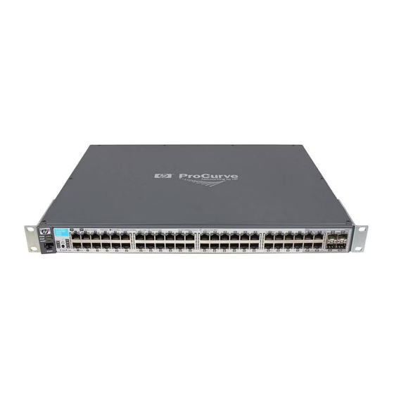
Introducing the Switch The HP ProCurve 2910al Switches are multiport switches that can be used to build high-performance switched networks. These switches are store-and- forward devices offering low latency for high-speed networking. The 2910al switches also support Redundant Power Supply and Power over Ethernet technologies. - Page 10 Introducing the Switch The 2910al-24G Switch and 2910al-48G Switch have respectively, 24 or 48, auto-sensing 10/100/1000Base-T RJ-45 ports, four dual-personality ports— either auto-sensing 10/100/1000Base-T RJ-45 or mini-GBIC, and two slots are provided in the back of the device to support expansion modules: 2-port (two fixed CX4 ports) 10 Gigabit per second Ethernet (10-GbE) ■...
- Page 11 Introducing the Switch The 2910al-PoE+ Switches also support Power over Ethernet+ (PoE+) technology. PoE+ offers a higher wattage per port than the previous PoE offering, 30 watts per port instead of 15. The switches support 802.3af standard devices and some pre-standard PoE devices. It also supports the draft version of the 802.3at standard.
-
Page 12: Front Of The Switch
10/100/1000Base-T RJ-45 button and indicator LEDs Console port Dual-personality ports Reset and Clear (1000Base-T or mini-GBIC) buttons Figure 1-1. HP ProCurve 2910al-24G Switch PoE, Temp, Fan, and Power, Switch port LEDs Test Status LEDs Fault, and Locator Module, and RPS,... - Page 13 Port LED Mode select button and indicator LEDs Console port 10/100/1000Base-T RJ-45 Dual-personality ports (1000Base-T or mini-GBIC) Reset and Clear buttons Figure 1-3. HP ProCurve 2910al-24G-PoE+ Switch PoE, Temp, Fan, and Power, Test Status LEDs Fault, and locator LEDs Switch port LEDs...
-
Page 14: Network Ports
Introducing the Switch Front of the Switch Network Ports ■ 24 or 48 auto-sensing 10/100/1000Base-T ports. All these ports have the “Auto MDIX” feature, which means you can use either straight-through or crossover twisted-pair cables to connect any network devices to the switch. ■... - Page 15 Introducing the Switch Front of the Switch Switch LEDs State Meaning Locator (Blue) The Locator LED is used to locate a specific chassis in a area full of chassis. The Blinking LED can be set to be on solid or blink for a specified number of minutes (1-1440). The default is 30 minutes.
-
Page 16: Led Mode Select Button And Indicator Leds
Introducing the Switch Front of the Switch Switch LEDs State Meaning RPS Status Normal operation. RPS is connected and operating correctly. RPS could be powering the unit. (green) Blinking RPS is connected but has experienced a fault. RPS is not connected or is not powered on. EPS Status Connected to an External Power Supply, and receiving power. - Page 17 Link Mode Link Mode Reset Clear LED Mode select button and indicator LEDs Figure 1-5. HP ProCurve 2910al-48G Switch Expansion Module LEDs Port LEDs Link and Mode Status of the Back Spd mode: off=10 Mbps, 2 flash=100 Mbps, on=1 Gbps, 3 flash=10 Gbps PoE+ Integrated 10/100/1000Base-T Ports (1 - 48T) —...
-
Page 18: Reset Button
Introducing the Switch Front of the Switch The Usr Mode LED is reserved for future development ■ ■ If the PoE indicator LED is lit, the Link and Mode LEDs indicate PoE status: Link LED: • On = PoE is enabled on this port •... -
Page 19: Console Port
Introducing the Switch Front of the Switch Console Port This port is used to connect a console to the switch by using the RJ-45 to DB9 cable, supplied with the switch. This connection is described under “Connect a Console to the Switch” in chapter 2, “Installing the Switch.” The console can be a PC or workstation running a VT-100 terminal emulator, or a VT-100 terminal. -
Page 20: Back Of The Switch
100-127 V~ 10 A 200-240 V~ 5 A RPS Input Port AC power connector al module slots Auxiliary Port and LED Figure 1-7. HP ProCurve 2910al-48G Switch EPS Input Port Serial No. SG12345678 CAUTION: MULTIPLE POWER SOURCES System MAC Address... -
Page 21: Rps And Eps Input Ports
RPS and EPS Input Ports The 2910al Switches support connectivity to a redundant power supply. Currently the 2910al Switches support the HP ProCurve 620 Redundant and External Power Supply (J8696A) for RPS power only. The External Power Supply will provide redundant power (RPS) to the switch products to back up the power supply in the switch in case of loss of the internal power supply. -
Page 22: Hp Procurve Switch Al Modules
These modules come in a kit of 2 modules with one 0.5 meter cable. Supported accessories: As of this printing the following HP ProCurve accessories are supported by the HP ProCurve Switch 2-Port 10-GbE CX4 al Module: • ProCurve 10-GbE CX4 Media Converter (J8439A). -
Page 23: Features
Introducing the Switch Features Features HP ProCurve 10-GbE CX4 al Module Module Status LEDs Retaining screw Link and Mode LEDs Copper CX4 port connections (one pair per port) Figure 2. Front of the al 10-GbE CX4 Module The al Modules have the following features: ■... -
Page 24: Switch Features
Introducing the Switch Switch Features Switch Features The features of the 2910al Switch include: ■ 24 or 48 auto-sensing 10/100/1000Base-T RJ-45 ports with Auto-MDIX. ■ Four dual-personality ports—either the auto sensing 10/100/1000Base-T RJ-45 or the mini-GBIC can be used for each port. ■... - Page 25 Introducing the Switch Switch Features ■ Support for the Spanning Tree Protocol to eliminate network loops Support for up to 256 IEEE 802.1Q-compliant VLANs so you can divide ■ the attached end nodes into logical groupings that fit your business needs. ■...
-
Page 27: Installing The Switch
C a u t i o n If the switch is to be shipped in a rack, be sure to use only an HP 10K rack. Mount the switch using rail kit, ProCurve 1U RK MT SWITCH 10K ALL, part number 356578-B21 and shelf kit AB469A, HP rx 16/26 Factory Rackmount Shelf Kit. - Page 28 Installing the Switch Included Parts ■ Accessory kit (5069-5705) two mounting brackets eight 8-mm M4 screws to attach the mounting brackets to the switch four 5/8-inch number 12-24 screws to attach the switch to a rack four rubber feet ■ Power cord, one of the following: Non-PoE Switches PoE+ Switches...
-
Page 29: Installation Precautions
C a u t i o n s ■ If the switch is to be shipped in a rack, be sure to use only an HP 10K rack. Mount the switch using rail kit part number 356578-B21 and shelf kit AB469A. -
Page 30: Installation Procedures
Installing the Switch Installation Procedures Figure 2-1. Air flow direction of the 2910al switch Installation Procedures Summary Prepare the installation site (page 2-5). Ensure the physical environ- ment is properly prepared, including having the correct network cabling ready to connect to the switch and having an appropriate location for the switch. -
Page 31: Prepare The Installation Site
Installing the Switch Installation Procedures (Optional) Connect a console to the switch (page 2-21). You may wish to modify the switch’s configuration, for example, to configure an IP address so it can be managed using a web browser, from an SNMP network management station, or through a Telnet session. - Page 32 Installing the Switch Installation Procedures Connect the power cord supplied with the switch to the power connector on the back of the switch, and then into a properly grounded electrical outlet. Figure 2-2. Connecting the power cord N o t e These switches do not have a power switch.
-
Page 33: Led Behavior
Installing the Switch Installation Procedures Switch port LEDs Power and Fault LEDs Status of the Back Spd mode: off=10 Mbps, 2 flash=100 Mbps, on=1 Gbps, 3 flash=10 Gbps PoE+ Integrated 10/100/1000Base-T Ports (1 - 48T) — Ports are Auto-MDIX ProCurve Switch 2910bl-48G-PoE Link Mode... -
Page 34: Optional) Install A Module
If you install or remove an expansion al module with the switch powered on, a reboot may be required for the module to be recognized. HP ProCurve recommends inserting or removing modules during scheduled downtime with the switch powered off. -
Page 35: Installing The Interconnect Kit
Installing the Switch Installation Procedures Installing the Interconnect Kit The Interconnect Kit consists of two, 1-port 10 Gigabit switch expansion modules (J9165A) and one 0.5 meter cable used specifically for this interconnect kit. These modules have 1 fixed CX4 port each. The interconnect kit is used for 10-GbE (high speed) connectivity. -
Page 36: Verifying The Module Is Installed Correctly
Installing the Switch Installation Procedures Verifying the Module is Installed Correctly Observe the Module Status and Fault LEDs on the front of the switch to verify the module is installed properly. Module Status LED Status of the Back ProCurve Switch 2910bl-24G-PoE J9146A PoE+... -
Page 37: Mount The Switch
Installing the Switch Installation Procedures 4. Mount the Switch After the switch passes self test, it is ready to be mounted in a stable location. The 2910al Switches can be mounted in these ways: Mounting Location Non-PoE Switches PoE Switches In a rack or cabinet On a horizontal surface On a wall... - Page 38 Installing the Switch Installation Procedures 8 mm M4 screws Figure 2-9. Attaching mounting brackets N o t e The mounting brackets have multiple mounting holes and can be rotated allowing for a wide variety of mounting options. These include mounting the switch so its front face is flush with the face of the rack, or mounting it in a more balanced position.
-
Page 39: Horizontal Surface Mounting
Installing the Switch Installation Procedures Hold the switch with attached brackets up to the rack and move it vertically until rack holes line up with the bracket holes, then insert and tighten the four number 12-24 screws holding the brackets to the rack. Figure 2-10. -
Page 40: Optional) Install A Transceiver
Installing the Switch Installation Procedures 5. (Optional) Install a Transceiver N o t e Hot swapping transceivers is supported. You can install or remove a transceiver with the switch powered on, a reset will not occur. However, rapid hotswaps are not recommended. Wait 5 seconds between hotswaps. a. -
Page 41: Installing Or Removing The Optical Media Converter
Installation Procedures Installing or Removing the Optical Media Converter You can connect an Optical Media Converter (OMC) to the fixed ports only. Use only HP ProCurve OMCs. Installing the OMC: Connect the OMC to the fixed port. Push it until it clicks. -
Page 42: Optional) Install Mini-Gbics And Sfps
Installing the Switch Installation Procedures 6. (Optional) Install Mini-GBICs and SFPs You can install or remove a mini-GBIC from a mini-GBIC slot without having to power off the switch. Use only ProCurve mini-GBICs. When a mini-GBIC or SFP transceiver is inserted the switch authenticates it. This can take 1-3 seconds, with the worst case being 5 seconds. -
Page 43: Removing The Mini-Gbics
Installing the Switch Installation Procedures N o t e Direct Attach Cables (DACs) are low- cost 10-GbE connectivity options consisting of a one, three, or seven meter cable with SFP+ connectors permanently attached to each end. Figure 2-13. One meter DAC Installing the mini-GBICs Hold the mini-GBIC by its sides and gently insert it into one of the slots on the switch until the mini-GBIC clicks into place. -
Page 44: Connect The Switch To A Power Source
Installing the Switch Installation Procedures To remove the mini-GBICs that have the plastic tab or plastic collar, push the tab or collar toward the switch until you see the mini-GBIC release from the switch (you can see it move outward slightly), and then pull it from the slot. To remove the mini-GBICs that have the wire bail, lower the bail until it is approximately horizontal, and then using the bail, pull the mini-GBIC from the slot. -
Page 45: Rps Operation
Installing the Switch Installation Procedures RPS Operation The RPS portion of the 620 RPS/EPS monitors the power signal from the switch by detecting that the 620 RPS/EPS is connected to a switch with an RPS cable. When the power from the switch is no longer detected, the 620 RPS/EPS will provide power to the switch within 1 millisecond. - Page 46 Installing the Switch Installation Procedures Table 2-1. 620 RPS/EPS LEDs State Meaning Power The unit is powered on. (green) The unit is NOT powered on. Fault The normal state; indicates that there are no fault conditions on the unit. (orange) Blink A fault has occurred on the unit, one of the ports, or the fan.
-
Page 47: 620 Rps/Eps Connectivity
Installing the Switch Installation Procedures 620 RPS/EPS Connectivity This section shows some recommended connection topologies using the 620 RPS/EPS. The 620 RPS/EPS can provide backup power support for up to two ProCurve switches. In the illustration below, two ProCurve Switch 2910s are connected to the RPS ports on a 620 RPS/EPS. -
Page 48: Terminal Configuration
Installing the Switch Installation Procedures ■ In-Band: Access the console using Telnet from a PC or UNIX station on the network, and a VT-100 terminal emulator. This method requires that you first configure the switch with an IP address and subnet mask by using either out-of-band console access or through DHCP/Bootp. -
Page 49: Direct Console Access
Installing the Switch Installation Procedures Direct Console Access To connect a console to the switch, follow these steps: Connect the PC or terminal to the switch’s Console port Console Port using the console cable included with the Switch. (If your PC or terminal has a 25-pin Console cable supplied serial connector, first... - Page 50 Installing the Switch Installation Procedures 1 2 3 4 5 6 7 8 1 2 3 4 5 6 7 8 Figure 2-18. RJ-45 to DB-9 pinouts Table 2-2. Mapping of RJ-45 to DB-9 RJ-45 (Signal reference from DB-9 (Signal reference from PC) Chassis TX_Debug RX_Debug...
-
Page 51: 10. Connect The Network Cables
Installing the Switch Installation Procedures 10. Connect the Network Cables Connect the network cables, described under “Cabling Infrastructure” (page 2-5), from the network devices or your patch panels to the fixed RJ-45 ports on the switch or to any mini-GBICs you have installed in the switch. Using the RJ-45 Connectors To connect: Push the RJ-45 plug into the RJ-45 jack... -
Page 52: Connecting A Fiber Cable
Installing the Switch Installation Procedures Connecting a fiber cable To connect: 1. Remove the dust covers from the cable connectors and the port. 2. Aligning the notches on the cable connectors with the slots of the port, press the cable connector into the port until it snaps into place. -
Page 53: Sample Network Topologies
Installing the Switch Sample Network Topologies Sample Network Topologies This section shows a few sample network topologies in which the switch is implemented. For more topology information, see the ProCurve network products Website, www.procurve.com. Servers ProCurve Switch 5406zl Gigabit fiber cable ProCurve Switch 2910al Gigabit copper cable PCs and peripherals... - Page 54 Installing the Switch Sample Network Topologies Servers 10 Gigabit copper cables ProCurve Switch 5406zl 10 Gigabit fiber cable ProCurve Switch 2910al Gigabit copper cable Gigabit copper cable PCs and peripherals Figure 2-20. Example, high performance edge deployment 2-28...
- Page 55 Installing the Switch Sample Network Topologies High speed internet uplinks 10 Gigabit copper cables ProCurve Switch 5412zl 10 Gigabit copper cables 10 Gigabit fiber cable ProCurve Switch 2910al Gigabit copper Gigabit copper cable cable Servers with Gigabit Servers with Gigabit Ethernet NIC Ethernet NIC Figure 2-21.
- Page 56 Servers ProCurve Switch 5406zl 10 Gigabit fiber cable 10 Gigabit copper cables ProCurve Switch 2910al Gigabit copper cable PCs, peripherals and access points Figure 2-22. Example, PoE edge deployment...
-
Page 57: Getting Started With Switch Configuration
Getting Started With Switch Configuration This chapter is a guide for using the console Switch Setup screen to quickly assign an IP (Internet Protocol) address and subnet mask to the switch, set a Manager password, and, optionally, configure other basic features. For more information on using the switch console and the other switch management interfaces: the web browser interface and the SNMP manage- ment tool, ProCurve Manager, please see the Management and Configuration... -
Page 58: Using The Console Setup Screen
Getting Started With Switch Configuration Using the Console Setup Screen N o t e By default, the switch is configured to acquire an IP address configuration from a DHCP or Bootp server. To use DHCP/Bootp instead of the manual method described in this chapter, see “DHCP/Bootp Operation” in the Management and Configuration Guide, which is on the ProCurve Website at www.procurve.com/manuals. - Page 59 Getting Started With Switch Configuration Using the Console Setup Screen to the IP Config (DHCP/Bootp) field and use the Space bar to select the [Tab] Manual option. to the IP Address field and enter the IP address that is compatible with [Tab] your network.
-
Page 60: Where To Go From Here
Getting Started With Switch Configuration Where to Go From Here Where to Go From Here The above procedure configures your switch with a Manager password, IP address, and subnet mask. As a result, with the proper network connections, you can now manage the switch from a PC equipped with Telnet, a web browser interface, or from an SNMP-based network management station using a tool such as ProCurve Manager. -
Page 61: Using The Ip Address For Remote Switch Management
Getting Started With Switch Configuration Using the IP Address for Remote Switch Management Using the IP Address for Remote Switch Management With your switch, you can use the switch’s IP address to manage the switch from any PC that is on the same subnet as the switch. You can use either a Telnet session or a standard web browser to manage the switch. - Page 62 Getting Started With Switch Configuration Using the IP Address for Remote Switch Management The operating systems, web browsers, and Java support required to manage the switch through the browser interface are listed in the following table: Operating System Internet Explorer Java Version Windows 2000 SP4 5.5 SP2, 6.0 SP1...
-
Page 63: Troubleshooting
(page 4-11) Downloading New Switch Software (page 4-12) ■ ■ HP Customer Support Services (page 4-12) Basic Troubleshooting Tips Most problems are caused by the following situations. Check for these items first when starting your troubleshooting: ■ Connecting to devices that have a fixed full-duplex configuration. - Page 64 Troubleshooting Basic Troubleshooting Tips Because the switch behaves in this way (in compliance with the IEEE 802.3 standard), if a device connected to the switch has a fixed configu- ration at full duplex, the device will not connect correctly to the switch. The result will be high error rates and very inefficient communications between the switch and the device.
- Page 65 Troubleshooting Basic Troubleshooting Tips ■ Check the port configuration. A port on your switch may not be operating as you expect because it has been put into a “blocking” state by Spanning Tree, GVRP (automatic VLANs), or LACP (automatic trunking). (Note that the normal operation of the Spanning Tree, GVRP, and LACP features may put the port in a blocking state.) Or, the port just may have been configured as disabled through software.
-
Page 66: Diagnosing With The Leds
Troubleshooting Diagnosing with the LEDs Diagnosing with the LEDs Table 4-1 shows LED patterns on the switch and the switch modules that indicate problem conditions. Check in the table for the LED pattern you see on your switch. Refer to the corresponding diagnostic tip on the next few pages. Table 4-1. -
Page 67: Diagnostic Tips
Try power cycling the switch. If the fault indication reoccurs, the switch may have failed. hardware failure Call your ProCurve authorized LAN dealer, or use the electronic support services from HP has occurred. All to get assistance. See the Customer Support/Warranty booklet for more information. - Page 68 – For twisted-pair connections to the fixed 10/100 or 10/100/1000 ports, if the port is configured to “Auto” (auto negotiate), either straight-through or crossover cables can be used because of the switch’s “HP Auto-MDIX” feature and the Auto MDI/ MDI-X feature of the 10/100/1000-T port.
- Page 69 Troubleshooting Diagnosing with the LEDs Problem Solution ➐ The port may be Use the switch console to see if the port is part of a dynamic trunk (through the LACP improperly feature) or to see if Spanning Tree is enabled on the switch, and to see if the port may configured, or have been put into a “blocking”...
-
Page 70: Proactive Networking
Troubleshooting Proactive Networking Proactive Networking The ProCurve 2910al Switches have built-in management capabilities that proactively help you manage your network including: ■ finding and helping you fix the most common network error conditions (for example, faulty network cabling, and non-standard network topolo-... -
Page 71: Hardware Diagnostic Tests
Troubleshooting Hardware Diagnostic Tests Hardware Diagnostic Tests Testing the Switch by Resetting It If you believe the switch is not operating correctly, you can reset the switch to test its circuitry and operating code. To reset a switch, either: ■ unplug and plug in the power cord (power cycling) press the Reset button on the front of the switch ■... -
Page 72: Testing Twisted-Pair Cabling
Troubleshooting Hardware Diagnostic Tests Testing Twisted-Pair Cabling Network cables that fail to provide a link or provide an unreliable link between the switch and the connected network device may not be compatible with the IEEE 802.3 Type 10Base-T, 100Base-TX, or 1000Base-T standards. The twisted- pair cables attached to the Switch must be compatible with the appropriate standards. -
Page 73: Restoring The Factory Default Configuration
Troubleshooting Restoring the Factory Default Configuration Restoring the Factory Default Configuration As part of your troubleshooting process on the switch, it may become neces- sary to return the switch configuration to the factory default settings. This process momentarily interrupts the switch operation, clears any passwords, clears the console event log, resets the network counters to zero, performs a complete self test, and reboots the switch into its factory default configuration including deleting the IP address, if one is configured. -
Page 74: Downloading New Switch Software
The new switch software would be available on the ProCurve Website at www.procurve.com/software. HP Customer Support Services If you are still having trouble with your switch, Hewlett-Packard offers support 24 hours a day, seven days a week through the use of a number of automated electronic services. -
Page 75: A Switch Specifications
Switch Specifications Physical 2910al-24G (J9145A) 2910al-48G (J9147A) 2910al-24G-PoE+ (J9146A) 2910al-48G-PoE+ (J9148A) Width: 44.19 cm (17.4 in) 44.19 cm (17.4 in) 44.19 cm (17.4 in) 44.19 cm (17.4 in) Depth: 36.57 cm (14.4 in) 36.57 cm (14.4 in) 36.57 cm (14.4 in) 36.57 cm (14.4 in) Height: 4.4 cm (1.7 in) -
Page 76: Acoustic
Switch Specifications Acoustic ProCurve Switch 2910al-24G (J9145A) Geraeuschemission LpA=41.1 dB am fiktiven Arbeitsplatz nach DIN 45635 T.19 Noise Emission LpA=41.1 dB at virtual workspace according to DIN 45635 T.19 ProCurve Switch 2910al-48G (J9147A) Geraeuschemission LpA=41.1 dB am fiktiven Arbeitsplatz nach DIN 45635 T.19 Noise Emission LpA=41.1 dB at virtual workspace according to DIN 45635 T.19... - Page 77 Switch Specifications Table A-1. Technology standards and safety compliance Laser safety information Technology Compatible with EN/IEC SFP ("mini-GBIC") Lasers SFP+ Media these IEEE standard Lasers Converter standards compliance Lasers 10/100/1000-T IEEE 802.3 10BASE-T, IEEE 802.3u 100BASE-TX, IEEE 802.3ab 1000BASE-T 100-FX IEEE 802.3u EN/IEC Class 1 Laser Product...
-
Page 79: B Module Specifications
Module Specifications Module Specifications Physical Modules Width: 106.17 mm (4.18 in) Depth: 104.39 mm (4.11 in) Height: 35.56 mm (1.40 in) Weight: 0.159 kg (.35 lbs) Environmental MODULE Operating Non-Operating Temperature: 0°C to 55°C (32°F to 131°F) -40°C to 70°C (-40°F to 158°F) Relative humidity: 15% to 95% at 40°C (104°F) 15% to 90% at 65°C (149°F) -
Page 81: C Cabling And Technology Information
Cabling and Technology Information This appendix includes network cable information for cables that should be used with the Switch 2910al, including minimum pin-out information and specifications for twisted-pair cables. N o t e Incorrectly wired cabling is the most common cause of problems for LAN communications. - Page 82 Cabling and Technology Information Note on 1000Base-T Cable Requirements. The Category 5 networking cables that work for 100Base-TX connections should also work for 1000Base-T, as long as all four-pairs are connected. But, for the most robust connections you should use cabling that complies with the Category 5e specifications, as described in Addendum 5 to the TIA-568-A standard (ANSI/ TIA/EIA-568-A-5).
-
Page 83: Technology Distance Specifications
Cabling and Technology Information Technology distance specifications Table C-2. Technology Supported cable type Multimode fiber Supported distances modal bandwidth 100-FX multimode fiber up to 2,000 meters 100-BX single mode fiber 0.5 - 10,000 meters 1000-T twisted-pair copper up to 100 meters 1000-SX multimode fiber 160 MHz*km... -
Page 84: Mode Conditioning Patch Cord
Cabling and Technology Information Mode Conditioning Patch Cord The following information applies to installations in which multimode fiber- optic cables are connected to a Gigabit-LX port or a 10-Gigabit LRM port. Multimode cable has a design characteristic called “Differential Mode Delay”, which requires the transmission signals be “conditioned”... -
Page 85: Installing The Patch Cord
Cabling and Technology Information Installing the Patch Cord As shown in the illustration below, connect the patch cord to the ProCurve transceiver with the section of single mode fiber plugged in to the Tx (transmit) port. Then, connect the other end of the patch cord to your network cabling patch panel, or directly to the network multimode fiber. -
Page 86: Twisted-Pair Cable/Connector Pin-Outs
Cabling and Technology Information Twisted-Pair Cable/Connector Pin-Outs Auto-MDIX Feature: The 10/100/1000-T ports support the IEEE 802.3ab standard, which includes the “Auto MDI/MDI-X” feature. In the default configuration, “Auto”, the ports on the Switch 2910al all automatically detect the type of port on the connected device and operate as either an MDI or MDI- X port, whichever is appropriate. -
Page 87: Straight-Through Twisted-Pair Cable For 10 Mbps Or 100 Mbps Network Connections
Straight-Through Twisted-Pair Cable for 10 Mbps or 100 Mbps Network Connections Because of the HP Auto-MDIX operation of the 10/100 ports on the switch, for all network connections, to PCs, servers or other end nodes, or to hubs or other switches, you can use straight-through cables. -
Page 88: Crossover Twisted-Pair Cable For 10 Mbps Or 100 Mbps Network Connection
Crossover Twisted-Pair Cable for 10 Mbps or 100 Mbps Network Connection The HP Auto-MDIX operation of the 10/100 ports on the switch also allows you to use crossover cables for all network connections, to PCs, servers or other end nodes, or to hubs or other switches. -
Page 89: Straight-Through Twisted-Pair Cable For 1000 Mbps Network Connections
Cabling and Technology Information Straight-Through Twisted-Pair Cable for 1000 Mbps Network Connections 1000Base-T connections require that all four pairs or wires be connected. Cable Diagram N o t e Pins 1 and 2 on connector “A” must be wired as a twisted pair to pins 1 and 2 on connector “B”. -
Page 91: D Safety And Emc Regulatory Statements
Safety and EMC Regulatory Statements Safety Information Documentation reference symbol. If the product is marked with this symbol, refer to the product documentation to get more information about the product. WARNING A WARNING in the manual denotes a hazard that can cause injury or death. -
Page 92: Informations Concernant La Sécurité
Safety and EMC Regulatory Statements Informations concernant la sécurité Informations concernant la sécurité Symbole de référence à la documentation. Si le produit est marqué de ce symbole, reportez-vous à la documentation du produit afin d'obtenir des informations plus détaillées. WARNING Dans la documentation, un WARNING indique un danger susceptible d'entraîner des dommages corporels ou la mort. -
Page 93: Hinweise Zur Sicherheit
Safety and EMC Regulatory Statements Hinweise zur Sicherheit Hinweise zur Sicherheit Symbol für Dokumentationsverweis. Wenn das Produkt mit diesem Symbol markiert ist, schlagen Sie bitte in der Produktdokumentation nach, um mehr Informationen über das Produkt zu erhalten. WARNING Eine WARNING in der Dokumentation symbolisiert eine Gefahr, die Verletzungen oder sogar Todesfälle verursachen kann. -
Page 94: Considerazioni Sulla Sicurezza
Safety and EMC Regulatory Statements Considerazioni sulla sicurezza Considerazioni sulla sicurezza Simbolo di riferimento alla documentazione. Se il prodotto è contras- segnato da questo simbolo, fare riferimento alla documentazione sul prodotto per ulteriori informazioni su di esso. WARNING La dicitura WARNINGdenota un pericolo che può causare lesioni o morte. -
Page 95: Consideraciones Sobre Seguridad
Safety and EMC Regulatory Statements Consideraciones sobre seguridad Consideraciones sobre seguridad Símbolo de referencia a la documentación. Si el producto va marcado con este símbolo, consultar la documentación del producto a fin de obtener mayor información sobre el producto. WARNING Una WARNING en la documentación señala un riesgo que podría resultar en lesiones o la muerte. -
Page 96: Safety Information (Japan
Safety and EMC Regulatory Statements Safety Information (Japan) Safety Information (Japan) J a p a n P o w e r C o r d W a r n i n g... -
Page 97: Safety Information (China
Safety and EMC Regulatory Statements Safety Information (China) Safety Information (China) -
Page 98: Emc Regulatory Statements
Safety and EMC Regulatory Statements EMC Regulatory Statements EMC Regulatory Statements U.S.A. FCC Class A This equipment has been tested and found to comply with the limits for a Class A digital device, pursuant to Part 15 of the FCC Rules. These limits are designed to provide reasonable protection against interference when the equipment is operated in a commercial environment. -
Page 99: Korea
Safety and EMC Regulatory Statements EMC Regulatory Statements Korea Taiwan... -
Page 100: European Community
Regulatory Model Number is the main product identifier in the regulatory documentation and test reports, this number should not be confused with the marketing name or the product numbers. 2) This product was tested with HP branded products only. Roseville, 26-November-2008 Local contact for regulatory information: EMEA: Hewlett-Packard GmbH, HQ-TRE, Herrenberger Straße 140, D-71034 Böblingen, Germany... - Page 101 Regulatory Model Number is the main product identifier in the regulatory documentation and test reports, this number should not be confused with the marketing name or the product numbers. 2) This product was tested with HP branded products only. Roseville, 01-December-2008 Local contact for regulatory information: EMEA: Hewlett-Packard GmbH, HQ-TRE, Herrenberger Straße 140, D-71034 Böblingen, Germany...
-
Page 103: E Recycle Statements
Recycle Statements Waste Electrical and Electronic Equipment (WEEE) Statements Disposal of Waste Equipment by Users in Private Household in the European Union This symbol on the product or on its packaging indicates that this product must not be disposed of with your other household waste. -
Page 104: Waste Electrical And Electronic Equipment (Weee) Statements
Recycle Statements Waste Electrical and Electronic Equipment (WEEE) Statements Laitteiden hävittäminen kotitalouksissa Euroopan unionin alueella Jos tuotteessa tai sen pakkauksessa on tämä merkki, tuotetta ei saa hävittää kotitalousjätteiden mukana. Tällöin hävitettävä laite on toimitettava sähkölaitteiden ja elektronisten laitteiden kierrätyspisteeseen. Hävitettävien laitteiden erillinen käsittely ja kierrätys auttavat säästämään luonnonvaroja ja varmistamaan, että... - Page 105 Recycle Statements Waste Electrical and Electronic Equipment (WEEE) Statements Smaltimento delle apparecchiature da parte di privati nel territorio dell'Unione Europea Questo simbolo presente sul prodotto o sulla sua confezione indica che il prodotto non può essere smaltito insieme ai rifiuti domestici. È responsabilità dell'utente smaltire le apparecchiature consegnan- dole presso un punto di raccolta designato al riciclo e allo smaltimento di apparecchiature elettriche ed elettroniche.
- Page 106 Para obter mais informações sobre locais que reciclam esse tipo de material, entre em contato com o escritório da HP em sua cidade, com o serviço de coleta de lixo ou com a loja em que o produto foi adquirido.
-
Page 107: Index
… C-8 install or remove … 2-8 cables, twisted-pair al module slot … 1-12 HP Auto-MDIX feature … C-6 auto MDI/MDI-X operation … C-7, C-9 wiring rules … C-6 HP Auto-MDIX feature … C-6 cables, twisted-pair connector pin-outs … C-6 cabling infrastructure …... - Page 108 EMC regulatory statements … D-8 environmental specifications, switch … A-1, B-1 horizontal surface EPS input port … 1-13 mounting switch on … 2-13 expansion module LEDs … 1-11 HP Auto-MDIX external power supply feature description … C-6 connecting … 2-18 2 – Index...
- Page 109 … 2-7 network cables blinking definition … 2-20 fiber-optic, specifications … C-3 checking during troubleshooting … 4-9 HP Auto-MDIX feature … C-6 descriptions of … 1-6 required types … 2-5 error indications … 4-4 twisted-pair connector pin-outs … C-6 Fan Status …...
- Page 110 … 2-25 Self Test LED … 1-7 console … 2-21 behavior during factory default reset … 4-11 HP Auto-MDIX feature … C-6 serial cable network connections … 2-25 for direct console connection … 2-23 power connector … 1-13 SFP+ …...
- Page 111 Temp Status LED … 2-20 testing … 4-10 terminal configuration … 2-22 twisted-pair ports Test LED HP Auto-MDIX feature … C-6 behavior during self test … 2-7 testing checking the console messages … 4-9 checking the LEDs … 4-9 Usr LEDs … 1-7 diagnostic tests …...
- Page 112 6 – Index...
- Page 114 To learn more, visit www.hp.com/go/procurve/ © Copyright 2009 Hewlett-Packard Development Company, L.P. The information contained herein is subject to change without notice. The only warranties for HP products and services are set forth in the express warranty statements accompanying such products and services.