
Related Manuals for Hitachi NV 75AG


Summary of Contents for Hitachi NV 75AG
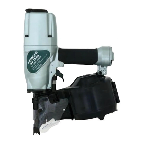
- Page 1 MODEL NV 75AG POWER TOOLS TECHNICAL DATA COIL NAILER NV 75AG SERVICE MANUAL LIST No. E006 Aug. 2002 SPECIFICATIONS AND PARTS ARE SUBJECT TO CHANGE FOR IMPROVEMENT...
- Page 2 REMARK: Throughout this TECHNICAL DATA AND SERVICE MANUAL, a symbol(s) is(are) used in the place of company name(s) and model name(s) of our competitor(s). The symbol(s) utilized here is(are) as follows: Competitors Symbols Utilized Company Name Model Name SCN60 SENCO...
-
Page 3: Table Of Contents
10-4. Disassembly and Reassembly of the Magazine Section ............. 28 10-5. Disassembly and Reassembly of the Driving Section ............31 10-6. Grip Rubber ......................... 35 11. INSPECTION AND CONFIRMATION AFTER REASSEMBLY ..........36 12. STANDARD REPAIR TIME (UNIT) SCHEDULES ............... 37 Assembly Diagram for NV 75AG... -
Page 4: Product Name
There is a demand for a high-power nailer capable of driving larger-diameter nails from the users of the Model NV 65AH. The new Model NV 75AG can also satisfy the above demand. Please expand the sales of the new Model NV 75AG. -
Page 5: Specifications
5. SPECIFICATIONS 5-1. Specifications NV 75AG Model Driving system Reciprocating piston type 5 --- 8.5 kgf/cm (70 -- - 120 psi, 4.9 --- 8.3 bar) (Gauge pressure) Operating pressure Driving speed 3 pcs./sec. Weight 2.5 kg (5.5 lbs.) Dimensions 271 mm x 338 mm x 132 mm (Length x height x width) (10-11/16"... -
Page 6: Nail Selection
5-2. Nail Selection The Model NV 75AG utilizes common round-head nails collated by wire or sheet into coils from 200 to 300 pieces. Applicable nail dimensions are shown below. However, it is recommended to use genuine HITACHI nails to ensure satisfactory driving quality. - Page 7 Unit: mm (inch) Type 2.5 --- 2.9 45 --- 65 (0.099 --- 0.113) (1-3/4 --- 2-1/2) 37.5 (2.835) (0.028) (0.748) (1.476) (1.102) (4.764) 65 --- 75 3.1 --- 3.3 (1-1/2 --- 3) (0.120 --- 0.131) (3.150) Fig. 2 Dimensions of wire-collated nails 2.3 --- 2.5 61.5 45 --- 57...
-
Page 8: Nail Driving Force
For example, when driving a nail of 3.3 mm dia. x 75 mm length (0.131" x 3") into a workpiece of hemlock with the Model NV 75AG, a pressure of about 8 bar (8.2 kgf/cm , 116 psi) allows the nailer to drive the nail flush with the wood surface. -
Page 9: Comparisons With Similar Products
--- 6 ---... -
Page 10: Precautions In Sales Promotion
7. PRECAUTIONS IN SALES PROMOTION In the interest of promoting the safest and most efficient use of the Model NV 75AG Nailer by all of our customers, it is very important that at the time of sale the salesperson carefully ensures that the buyer seriously recognizes the importance of the contents of the Instruction Manual, and fully understands the meaning of the precautions listed on the Warning Label attached to each tool. -
Page 11: Precautions In Operation
(2) If dust in the compressed air settles on the sliding portion, the Model NV 75AG will not operate properly. Lubrication is effective to remove dust and also to prolong the service life of the Model NV 75AG keeping good performance. -
Page 12: Mechanism And Operation Principle
8. MECHANISM AND OPERATION PRINCIPLE 8-1. Mechanism As illustrated in Fig. 7, the Model NV 75AG can be generally divided into four sections: Output section, control valve section, driving section and magazine section. The parts of the output section and the control valve section are the same as those of the Model NR 65AK to allow the use of nails 75 mm (3") long, though the basic construction is the same as the Model NV 65AH. - Page 13 Valve Piston (B) [57] Plunger Spring [58] Valve Bushing Top Cover [3] (B) [53] Exhaust Exhaust Cover [5] Plunger (A) [59] Valve Bushing vent (A) [61] Head Valve (A) [10] Control valve section Control valve section Accumulator Body [18] Trigger [39] Grip rubber Piston (H) (Driver blade)
-
Page 14: Interchangeability Of Parts
8-2. Interchangeability of Parts The driving section and the magazine section of the Model NV 75AG have been newly designed and there is no interchangeability with those of the Model NR 65AK. Although most parts of the output section and the control valve section of the Model NV 75AG are interchangeable with those of the Model NR 65AK, there is no interchangeability for the parts shown in the table below. -
Page 15: Operation Principle
8-3. Operation Principle (1) Prior to nailing (see Fig. 6) 1. When compressed air is supplied to the main body, it fills the accumulator (see diagram). Air passage (A) Head valve spring Air supply vent 2. At the same time, the compressed air flows into the Head valve Accumulator valve piston lower chamber of the control valve... - Page 16 (3) During nailing (II) (see Fig. 8) 1. When the piston moves down inside the cylinder, the air below the piston flows through air passage (C) under the cylinder and is accumulated in the Cylinder return air chamber together with the compressed air Cylinder hole flowing through the cylinder hole.
-
Page 17: Troubleshooting Guide
9. TROUBLESHOOTING GUIDE 9-1. Troubleshooting and Correction Possible cause Problem Inspection method Remedy : Most-common cause) 1) Nails cannot <Nails> be driven. Magazine is not loaded with Check that the magazine is Use specified nails. specified genuine nails. correctly loaded with Remove the abnormal nails Magazine is loaded with specified nails. - Page 18 Possible cause Problem Inspection method Remedy : Most-common cause) 1) Nails cannot Air leaks from the gap Tighten screws and check be driven. between the body and the the O-rings. (continued) nose. O-rings are worn or Replace the O-rings. deformed. O-rings need lubrication.
- Page 19 Possible cause Problem Inspection method Remedy : Most-common cause) 1) Nails cannot Cylinder inside surface is Remove dust and then Check that nails can be be driven. abnormal (packed with lubricate. driven at 5 kgf/cm (4.9 bar, (continued) dust, or worn). Replace the part.
- Page 20 Possible cause Problem Inspection method Remedy : Most-common cause) Driver blade is worn. Replace the part. Perform idle driving to check 3) Nails cannot the driver blade is projected be driven into from the nose tip. the workpiece completely: Disassemble the output Piston O-ring is abnormal Replace the abnormal part.
- Page 21 Possible cause Problem Inspection method Remedy : Most-common cause) <Body: Nail feeding is Open the nail guide and Replace the abnormal part. 4) Nails jam. check the position of the incomplete.> (continued) feeder claw. Feeder is worn and the sliding section is abnormal. Nail guide face of the nose or the sliding section of the feeder is abnormal...
-
Page 22: Possible Causes And Corrections Of Air Leakage
9-2. Possible Causes and Corrections of Air Leakage Air leakage repair location Repair procedure (1) Check the points of the following parts marked by an asterisk for abnormal condition. (2) Next, check the seal parts (marked with a double circle) for wear, flaws or damage. (3) And then, check other places. - Page 23 Cause Air leakage portion When the Trigger is turned on When the Trigger is turned off (A) Exhaust port Abnormality in Head Valve (A) [10] Abnormality in Head Valve (A) [10] and Cylinder [15] [Wear and [Wear, deformation and/or breakage deformation of the sealed face of the of the section (a)] (b) section]...
- Page 24 Cause Air leakage portion When the Trigger is turned on When the Trigger is turned off Abnormality (wear, breakage and/or Abnormality (wear, breakage and/or (G) Control valve 2 scratches) in O-ring (I.D 1.8) [60] of scratches) in O-ring (I.D 11) [56] in Plunger (A) [59] the inside of Valve Piston (B) [57] Abnormality (deformation and/or...
-
Page 25: Disassembly And Reassembly
Apply grease (Nippeco SEP-3A, Code No. 930035) to the O-rings and O-rings' sliding portions. When installing the O-rings, be careful not to damage the O-rings and prevent dirt entry. Oil required: Hitachi pneumatic tool lubricant 1 oz (30 cc) Oil feeder (Code No. 877153) 4 oz (120 cc) Oil feeder (Code No. -
Page 26: Disassembly And Reassembly Of The Output Section
10-2. Disassembly and Reassembly of the Output Section (See Fig. 10) [Tool required] Hex. Socket Hd. Bolt M6 x 12 [1] Hex. bar wrench (4 mm) (a) Disassembly Plate [2] Remove the Hex. Socket Hd. Bolts M6 x 12 Top Cover [3] [1] with a hex. - Page 27 Mount the Cylinder Plate [12] to the Cylinder [15] facing the stopper of the Cylinder Plate [12] to the Piston Bumper [20]. When mounting to the Body [18], fit the rib of the Body [18] into the stopper groove of the Cylinder Plate [12] (Figs. 11 and 12).
-
Page 28: Disassembly And Reassembly Of The Control Valve Section
10-3. Disassembly and Reassembly of the Control Valve Section (See Fig. 14) [Tools required] Roll pin puller (3 mm (0.118 ") dia.) Body [18] (a) Disassembly Pull out the Roll Pin D3 x 28 [38] with the roll Roll Pin D3 x 28 [38] pin puller (3 mm (0.118") dia.), remove the Pushing Lever Guide [40], and the Trigger [39] Trigger [39]... - Page 29 Pull out the Roll Pin D3 x 28 [38] with the roll Push pin puller (3 mm (0.118") dia.), and take out the control valve in the following manner. Body [18] 1) Remove the Exhaust Cover [5] by following Head Valve the procedure in (1), section 10-2.
- Page 30 (b) Reassembly Disassembly procedures should be followed in the reverse order. Note the following points: Be extremely careful to prevent the entry of foreign particles into the control valve section. Thoroughly apply grease to the O-Ring (I.D 1.8) [60] on Plunger (A) [59], O-Rings (I.D 11) [56], (S-18) [54] and (S-4) [48] on Valve Piston (B) [57], and the shaft of Plunger (A) [59] as shown in Fig.
-
Page 31: Disassembly And Reassembly Of The Magazine Section
10-4. Disassembly and Reassembly of the Magazine Section Tools required Phillips screwdriver Roll pin pullers (4 mm dia., 2.5 mm dia.) Hex. bar wrench (4 mm) Wrench M5 (1) Disassembly and reassembly of the magazine section (a) Disassembly (See Fig. 19.) Loosen the Hex. - Page 32 (b) Reassembly Disassembly procedures should be followed in the reverse order. Note the following points. Bend the tip of the Cover [95] and engage it with the convex portion of Magazine (A) [75]. Hold it with Pushing Lever Cover (A) [71] positioning the Cover [95] outside Pushing Lever Cover (A) [71]. Nylon Nut M5 [69] Machine Screw (W/Washers) Body [18]...
- Page 33 (2) Disassembly and reassembly of nail holder, holder shaft, etc. (a) Disassembly Pull out the two Pins [76] with a roll pin puller (4 mm dia.). Then Magazine (A) [75] and Magazine Cover (A) [78] can be removed. Remove Holder Cap (A) [79] and Roll Pin D2.5 x 12 [82] with a roll pin puller (2.5 mm dia.) Then O-ring (P-9) [62], Nail Holder [81], Holder Shaft (A) [83] and Spring [84] can be removed.
-
Page 34: Disassembly And Reassembly Of The Driving Section
10-5. Disassembly and Reassembly of the Driving Section Body [18] Retaining Ring for D28 Hole [68] O-ring (S-46) [13] Feed Piston Cover [67] Piston Bumper [20] Bumper [66] Feed Spring [65] Feed Piston [64] Nose [22] O-ring (P-21) [63] O-ring (P-4) [21] O-ring (P-9) [62] Nylock High Tension Bolt M6 x 20 [23]... - Page 35 (1) Disassembly and reassembly of Nose [22], Pushing Lever (A) [31] and other parts (a) Disassembly (See Figs. 21 and 22.) Remove the four Nylock High Tension Bolts M6 x 20 [23]. Then the Nose [22], Pushing Lever (A) [31] and other parts can be removed.
- Page 36 Adjuster [44] Adjuster Plate (B) [46] Adjuster Spring [45] Convex portion Adjuster Plate (A) [47] Bent portion Bent portion Fig. 23 (3) Disassembly and reassembly of Piston Bumper [20], Feeder [28], Feed Piston [64] and other parts. (See Fig. 24.) (a) Disassembly Remove the Nose [22] and the parts forming the pushing lever from the output section in accordance with the procedure in 10-5 (1).
- Page 37 Apply grease to the O-ring sliding surface of the Feed Piston [64] and the Nose [22]. However, be careful not to apply too much grease to the "A" surface shown in Fig. 25. Otherwise, the Feed Piston [64] operates improperly at the low pressure. Mount the Roll Pin D4 x 16 [25] facing its split toward the magazine as shown in Fig.
-
Page 38: Grip Rubber
10-6. Grip Rubber The Model NV 75AG is equipped wih the grip-rubber handle that is common to the Model NR 83AA2. However, the grip rubber is not supplied as a spare part because it is difficult to detach/attach the grip rubber. If replacement of the grip rubber is required, replace the Body [18] or attach the grip tape. -
Page 39: Inspection And Confirmation After Reassembly
11. INSPECTION AND CONFIRMATION AFTER REASSEMBLY Check that Plunger (A) [59] moves smoothly. Check that there is no air leakage from each part. While driving nails with an air pressure of 4.5 kgf/cm (63 psi), check that there is no idle driving and bending of nails. -
Page 40: Standard Repair Time (Unit) Schedules
12. STANDARD REPAIR TIME (UNIT) SCHEDULES Variable 60 min. MODEL Fixed Work Flow NV 75AG Cylinder Plate Exhaust Cover Cylinder Top Cover Piston Bumper Packing (B) O-ring x 3 Head Bumper Head Valve Spring O-ring x 2 Head Valve (A) - Page 41 LIST NO. E006 PNEUMATIC TOOL PARTS LIST COIL NAILER 2002 • • Model NV 75AG (E1)
- Page 42 PARTS NV 75AG ITEM CODE NO. DESCRIPTION REMARKS USED 949-657 HEX. SOCKET HD. BOLT M6X12 (10 PCS.) 880-515 PLATE 880-514 TOP COVER 949-822 HEX. SOCKET HD. BOLT M5X35 (10 PCS.) 883-451 EXHAUST COVER 883-452 GASKET (B) 882-914 HEAD BUMPER 882-913...
- Page 43 PARTS NV 75AG ITEM CODE NO. DESCRIPTION REMARKS USED 877-699 HEAD VALVE O-RING (I.D 16.8) 878-881 VALVE BUSHING (B) 878-885 O-RING (S-18) 878-925 O-RING (I.D 8.8) 878-887 O-RING (I.D 11) 880-672 VALVE PISTON (B) 878-884 PLUNGER SPRING 880-673 PLUNGER (A) 878-888 O-RING (I.D 1.8)
-
Page 44: Standard Accessories
NV 75AG STANDARD ACCESSORIES ITEM CODE NO. DESCRIPTION REMARKS USED 875-769 EYE PROTECTOR 943-277 HEX. BAR WRENCH 3MM 944-458 HEX. BAR WRENCH 4MM 944-459 HEX. BAR WRENCH 5MM --- 4 --- * ALTERNATIVE PARTS Printed in Japan 8 -- 02...