GE Profile PB975 Technical Service Manual
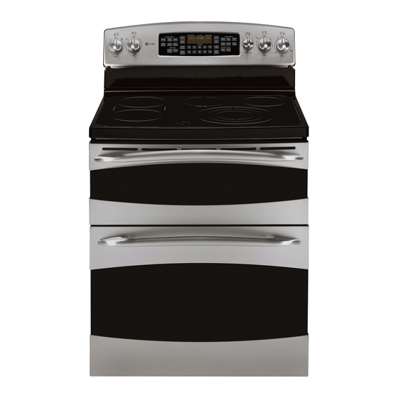
30-in. free standing double oven range
Hide thumbs
Also See for Profile PB975:
- Owner's manual (48 pages) ,
- Installation instructions manual (13 pages) ,
- Owner's manual (48 pages)

Related Manuals for GE Profile PB975


Summary of Contents for GE Profile PB975
- Page 1 GE Consumer & Industrial Technical Service Guide October 2007 Profi le 30-in. Free Standing Double Oven Range PB975 PB970 31-9157 GE Appliances General Electric Company Louisville, Kentucky 40225...
- Page 2 If grounding wires, screws, straps, clips, nuts, or washers used to complete a path to ground are removed for service, they must be returned to their original position and properly fastened. GE Consumer & Industrial Technical Service Guide Copyright © 2007 All rights reserved.
-
Page 3: Table Of Contents
Rear Cover Removal ...............................40 Schematics and Wiring Diagrams ..........................71 Side Panel Removal .................................41 Surface Unit Infi nite Switches ............................56 Tri-Ring Burner Size Switch (PB975)/Warmer Switch ..................57 Upper Oven Bake Element ............................50 Upper Oven Control Board ............................46 Upper Oven Door Assembly ............................34 Upper Oven Door Hinge ...............................45... -
Page 4: Introduction
Introduction GE introduced the new Profi le 30-in. free standing double oven range. It is available in two design choices - convection and non-convection lower ovens. These ranges feature electronic oven controls and surface unit dial controls that combine the precision of modern digital technology with the simplicity of traditional mechanical controls. -
Page 5: Nomenclature
Model Year Designator Feature Pack Designates features–the higher Glass Color the number, the more features Color Match Cook-Top PB975 Model shown Mini-Manual Serial Number The fi rst two numbers of the serial number identify the month and year of manufacture. Example:... -
Page 6: Control Features
Control Features Model PP975 Using the oven controls. NOTE: Throughout this manual, features and appearance may vary from your model. Features and appearance may vary. Oven Control, Clock and Timer Features and Settings BAKE Pad SELF CLEAN HI/LO pads to set the oven to start and stop automatically at a time Touch to select the bake function. - Page 7 Model PP970 Features and appearance may vary. Oven Control, Clock and Timer Features and Settings BAKE Pad COOK TIME Pad Touch to select the bake function. Touch and then touch the number pads to set the amount of time you want your food BROIL HI/LO Pad to cook.
- Page 8 How to Set the Upper Oven for Baking Touch the BAKE pad. Check food for doneness at minimum time on recipe. Cook Touch the number pads to set longer if necessary. the desired temperature. Touch the CLEAR/OFF pad when Touch the START pad. cooking is complete.
-
Page 9: Using The Timed Baking And Roasting Features
Using the timed baking and roasting features. (on some models) ge.com NOTE: Foods that spoil easily—such as milk, eggs, fish, stuffings, poultry and pork—should not be allowed to sit for more than 1 hour before or after cooking. Room temperature promotes the growth of harmful bacteria. Be sure that the oven light is off because heat from the bulb will speed harmful bacteria growth. - Page 10 How to Set the Lower Oven For Baking/Roasting When Using the Probe (on some models) Insert the probe fully into the food. After the internal temperature of the food reaches 100°F, the changing internal Plug the probe into the outlet in the temperature will be shown in the display.
- Page 11 Using the clock, kitchen timer and control lock. ge.com To Set the Clock The clock must be set to the correct time On some models, touch the of day for the automatic oven timing TIMER/CLOCK pad and hold for (on some models) functions to work properly.
- Page 12 Adjust the upper or lower oven thermostat—Do it yourself! You may find that your new oven cooks differently than the one it replaced. Use your new oven for a few weeks to become more familiar with it. If you still think your new oven is too hot or too cold, you can adjust the thermostat yourself.
- Page 13 Using the convection oven. (on some models) ge.com Convection Fan Operation In a convection oven, a fan circulates hot air over, NOTE: To maximize cooking evenness, under and around the food. the fan is designed to rotate in both directions, with a pause in between.
- Page 14 Using the convection oven. (on some models) Convection Roast Grid ■ Good for large tender cuts of meat, uncovered. When you are convection roasting it is Broiler pan important that you use a broiler pan and The convection fan circulates the heated grid for best convection roasting results.
-
Page 15: Using The Timed Features For Convection Cooking
Using the timed features for convection cooking. (on some models) ge.com You will hear a fan while cooking with these features. The fan will stop when the door is opened, but the heat will not turn off. NOTE: Foods that spoil easily—such as milk, eggs, fish, stuffings, poultry and pork—should not be allowed to sit for more than 1 hour before or after cooking. - Page 16 Using the timed features for convection cooking. (on some models) How to Set a Delayed Start and Automatic Stop The lower oven will turn on at the time of day you Touch the DELAY START pad. set, cook for a specific length of time and then turn Touch the number pads to set the off automatically.
- Page 17 Using the convection oven. (on some models) ge.com How to Set the Lower Oven for Convection Roasting when Using the Probe Place the oven rack in the position When the internal temperature of that centers the food between the the meat reaches the number you top and bottom of the oven.
- Page 18 Using the slow cook, pizza and warming features. How to Set the Lower Oven For Slow Cook Slow Cook is designed for long hours of When the Slow Cook function has unattended cooking. completed, the oven will go into the Warm mode.
- Page 19 How to Set the Upper Oven For Pizza Adjust rack position for type of pizza tray Type of Pizza Tray Rack Position being used (see chart). Tray supplied with fresh pizza Pizza placed directly on rack Touch the PIZZA pad Metal tray Touch the number pads to select 1 for fresh or 2 for frozen pizza.
- Page 20 Using the self-cleaning upper and lower ovens. Before a Clean Cycle We recommend venting your kitchen Soil on the front frame of the range and with an open window or using a outside the gasket on the door will need ventilation fan or hood during the to be cleaned by hand.
- Page 21 The oven doors must be closed and all controls set correctly for the cycle to work properly. How to Delay the Start of Cleaning Touch the SELF CLEAN HI/LO pad Touch the DELAY START pad. once for a 5-hour clean time or Using the number pads, enter the twice for a 3-hour clean time.
-
Page 22: Special Features Of Your Oven Control
Special features of your oven control. Your new touch pad control has additional features that you may choose to use. The following are the features and how you may activate them. The special feature modes can only be activated while the display is showing the time of day. They remain in the control’s memory until the steps are repeated. - Page 23 Tone Volume This feature allows you to adjust the tone volumes Touch the COOK TIME pad again. to a more acceptable volume. There are three The display will show 1 BEEP. This is possible volume levels. the quietest volume level. Touch the upper oven BROIL HI/LO For each time the level is changed, and BAKE pads at the same time...
- Page 24 Using the Sabbath feature. (upper and lower ovens) (Designed for use on the Jewish Sabbath and Holidays) (on some models) The Sabbath feature can be used for baking/roasting only. It cannot be used for convection, broiling, self-cleaning or Delay Start cooking. NOTE: The oven light comes on automatically (on some models) when the door is opened and goes off when the door is closed.
-
Page 25: Operational Notes
• On convection models, when in bake or timed Operational Notes baking is used, the bake, broil, and convection elements cycle during preheat with one element Certain modes, when selected, will automatically on at a time. The convection fan also operates enter into a preheat and 100°F will appear in while preheating and will turn off once the set the display. -
Page 26: Anti-Tip Bracket
Installation A range cord rated at 40 amps with 125/250 Electrical Requirements minimum volt range is required. A 50-amp range cord is not recommended but if used it should Caution: For personal safety, do not use an be marked for use with nominal 1 -in. -
Page 27: Component Locator Views
Component Locator Views Front View (PB975 shown) Control Panel (Continued next page) – 27 –... - Page 28 Ovens - Front View (PB975 shown) Broil Element Light Light Oven Temperature Sensor Bake Element Meat Probe Outlet Broil Element Light Light Oven Temperature Sensor Convection Fan and Element Hidden Bake Element Shown with oven doors removed (Continued next page)
- Page 29 Control Panel (PB975 shown) Electronic Range Control (ERC) Surface Unit Switch Surface Unit Switch Shown in service position Main Top (PB975 shown) Hot Surface Indicator Light Assembly Tri-Ring Element Bridge Element Right Rear Element Warming Zone Element (Continued next page)
- Page 30 Rear View (PB975 shown) Tri-Ring Burner Electronic Range Control (ERC)* Size Switch Surface Unit Switches Surface Unit Switches Upper Oven Door Upper Oven Lock Assembly Broil Element Oven Vent Tube Upper Oven Control Board Upper Oven Bake Element Lower Oven Door...
-
Page 31: Control Boards Connector Locator Views
Control Boards Connector Locator Views Lower Oven Control Board and Display Board Lower Oven Control Board Relay Jumper Wires Model Selector Harness Display Board J2 - Glass Touch Panel K1 - Oven Lights J3 - Glass Touch Panel K3 - Broil Element Relay J5 - Upper and Lower Oven Sensors K4 - Convection Fan Direction Relay J6 - Meat Probe... - Page 32 Upper Oven Control Board J7 - Lock Motor, Outer Broil Element, Oven Lights J11 - Neutral J14 - L1 supply to K3 and J7 J16 - Oven Lock Switch, Oven Unlock Switch J17 - Communication Cable K1 - Oven Lights K3 - Broil Relay K7 - Bake Relay K8 - Broil Boost Relay...
-
Page 33: Range Component Access Chart
Hot Surface Indicator Light Assembly Lock Assembly - Lower Oven Lock Assembly - Upper Oven Meat Probe and Outlet (PB975) Oven Light Assemblies (excluding upper oven right side) Oven Light Assembly (upper oven right side) Oven Liner - Upper Oven... -
Page 34: Range Components
Range Components 3. Close the door to the stop position. The hinge WARNING: Sharp edges may be exposed when servicing. Use caution to avoid injury. Wear Kevlar locks will contact the oven frame. gloves or equivalent protection. 4. Simultaneously press down on each release button located on the top of both hinges. - Page 35 To replace the upper oven door: Remove the six ¼-In. hex-head screws that attach the handle to the outer door assembly. Pull the hinges down away from the oven frame to the fully open position. Lift up on the hinge locks and rotate toward the oven frame until they stop.
-
Page 36: Lower Oven Door Assembly
To replace the inner door assembly: Lower Oven Door Assembly Remove the outer door assembly. (See previous The lower oven door can be separated into 2 page.) assemblies. The outer assembly consists of the outer panel, outer glass, and a replaceable door Remove the four T-20 Torx screws (2 on each handle. - Page 37 Lift door up until the hinge arm is clear of the To remove the outer door assembly: slot. Remove the door. (See previous page.) Place the door assembly, gasket side up, on a protective surface. Remove the 4 Phillips-head screws from the bottom of the outer door assembly.
- Page 38 To replace the inner door assembly: Remove the insulation and the inner glass assembly from the inner door. Remove the outer door assembly. (See previous page.) Remove the four T-20 Torx screws (2 on each side) that attach each door hinge to the inner door.
-
Page 39: Cooktop Assembly
Door Gaskets Cooktop Assembly The gasket forms a complete seal around the front The ceramic glass cooktop is sealed into the edge of the oven liner and the inner door panel. The cooktop frame and is not replaceable as a separate door gasket is attached to the inner door panel by part. -
Page 40: Rear Cover Removal
Note: The cooktop panel hinge slots rest on a hinge Rear Cover Removal pin mounted to each end plate. To remove the rear cover: Disconnect power to the range. Pull the range out from its installation. Remove and capture the hidden ¼-in. hex-head screw from the bottom of the cover. -
Page 41: Side Panel Removal
Remove the three top screws and maintop strike Side Panel Removal from the top of the side panel. The procedures to remove both the left and right side panels are identical. Disconnect power to the range. Remove the range from its installation. Raise and support the cooktop or remove the cooktop. -
Page 42: Oven Light Assemblies
Left Side Upper Oven Light Oven Light Assemblies Each oven is equipped with two halogen light assemblies. The light assemblies for the upper oven are located on the back wall of the oven. The light assemblies for the lower oven are located on the ceiling of the oven. - Page 43 Method #2: Oven Light Bulbs Disconnect power from the range. Caution: Before replacing your oven light bulb, disconnect the electrical power to the range at the Remove the range from the installation. main fuse or circuit breaker panel. Remove the rear panel. (See Rear Cover Removal Note: The glass cover should be removed only when cold.
-
Page 44: Door Switch
To replace a light bulb, use a new 130-volt halogen Insert a small fl at-blade screwdriver on one bulb, not to exceed 50 watts. of two spring clips and depress the spring clip while pulling the switch from the door frame. Note: Insert the small fl... -
Page 45: Cooktop Lockout Relay
Upper Oven Door Hinge Each upper oven door hinge is attached to the frame with two T-20 Torx screws. To replace it requires removing the upper oven door (See Upper .), then removing the side panel Oven Door Assembly (See Side Panel Removal. -
Page 46: Oven Components
Oven Components Upper Oven Control Board Oven Temperature Sensor To remove the upper oven control board: The oven temperature sensor has a resistance of: Ω at room temperature Remove the rear cover. (See • 1091 Rear Cover Removal Ω at 350°F Note: In the following step, do not remove the relay •... -
Page 47: Broil Element
Note: When reinstalling the sensor, use a small fl at- IMPORTANT: The lower wattage outer element blade screwdriver to push and guide the sensor wire utilizes -in. terminal connections. The higher harness into the oven liner. wattage inner element utilizes ¼-in. terminal connections. -
Page 48: Convection Element
3. Remove the four ¼-in. hex-head screws that Convection Element hold the convection element to the back wall of the oven cavity. • The element is rated at 2500 watts, has an approximate resistance value of 23 Ω, and draws approximately 10 amps. •... -
Page 49: Convection Fan Assembly
Remove the fan blade nut. Convection Fan Assembly The convection fan assembly is located on the back wall of the oven cavity and consists of the convection cover, fan blade, and motor. The fan motor utilizes a capacitor that can be accessed from the back of the range. -
Page 50: Lower Oven Bake Element
Upper Oven Bake Element Lower Oven Bake Element • The element is rated at 2500 watts, has an • The element is rated at 2650 watts, has an approximate resistance value of 23 Ω, and approximate resistance value of 21.7 Ω, and draws approximately 10 amps. -
Page 51: Meat Probe And Outlet (Pb975)
Tuck the insulation up under the 2 wire Meat Probe and Outlet (PB975) insulation retainers. The lower oven is equipped with a meat probe outlet. The meat probe outlet is connected to the lower oven control board in the control compartment at location J6. -
Page 52: Vent Tube/Smoke Eliminator
Remove the ¼-in. hex-head screw that holds the Vent Tube/Smoke Eliminator vent tube to the rear of the range. Each oven is equipped with an oven vent tube and a smoke eliminator. The vent tube and smoke eliminator for the upper oven are located on the top left rear corner of the oven cavity above the broiler element. -
Page 53: Upper Oven Liner
Note: It is not necessary to remove the lower Upper Oven Liner oven vent tube to remove the lower oven smoke eliminator. To remove the upper oven liner: To remove the lower oven vent tube, it is necessary Disconnect power to the range. to remove the rear cover. - Page 54 Release and remove the insulation retaining hooks from each side of the lower frame. Carefully lift and remove the insulation covering the liner. Remove the two ¼-in. hex-head screws that hold the vent to top of liner. (See Vent Tube/ Smoke Eliminator Remove the 5 screws and the clamp that hold the front of the liner to the oven frame.
-
Page 55: Control Panel
Remove all control panel knobs. Control Panel The control panel contains the ERC, infi nite heat switches, tri-ring burner size switch (PB975), and the warmer element switch. Remove the 4 glass touch panel retainer nuts To remove the control panel: that hold the glass touch panel to the control panel. -
Page 56: Surface Unit Infi Nite Switches
Place a protective cover on the main top. Surface Unit Infi nite Switches Using a stubby or off-set Phillips-head To remove the surface unit infi nite switch (1 of 4): screwdriver, remove the 2 inverted screws that attach the bottom of the control panel to the Pull out the knob, then loosen and remove the range. -
Page 57: Electronic Range Control (Erc) Assembly
Switch The electronic range control (ERC) assembly is located inside the control panel and consists of a To remove the tri-ring burner size switch (PB975)/ display board that plugs into the lower oven control Warmer switch: board. Both boards are installed in a frame attached Remove the glass touch panel. - Page 58 Remove the ERC assembly from the control Turn the frame over and remove the 5 Phillips- panel and place it display side up on a head screws that attach the control board to the protective surface. ERC frame. Caution: The screws that attach the display board are slightly longer than the screws that attach the control board.
-
Page 59: Radiant Heating Elements
Warming Zone switch attached to the heating element tray. The glass tube and metal rod extend across the center of the element. The rod's expansion and contraction Surface Element Ratings* - Model PB975 operate the contacts inside the switch. Element Wattage... -
Page 60: Hot Surface Indicator Light Assembly
To remove a radiant heating element: Hot Surface Indicator Light Assembly Remove the cooktop assembly. (See Cooktop The hot surface indicator lights are contained in an .) Place the cooktop upsidedown on a Assembly assembly located under the cooktop. protective surface. Each hot surface indicator light is controlled by the Caution: Routing of the wires is extremely critical. -
Page 61: Lock Assembly
Door Locked Lock Assembly Hook Pulled In - Top Switch Closed -Bottom Switch Open A motorized door lock assembly is located above Lock Assembly Wire Harness each oven, and they are identical. The assembly consists of a lock motor and switch assembly, cam, lock hook, heat barrier, and mounting plate. - Page 62 Upper Oven Door Lock Assembly Remove the six ¼-in. hex-head screws that attach the top brace to the range. Remove the To remove the upper oven door lock assembly: brace. Note: If only the lock motor and switch assembly and/or cam has failed, it may not be necessary to remove the door lock assembly from the range.
- Page 63 Grasp the rear of the lock assembly. Lift and rotate it approximately 40 degrees clockwise and pull it out approximately 1 inch. Lift the front of the mounting plate and guide it through the opening located under the rear of the cooktop.
-
Page 64: Diagnostics And Service Information
Diagnostics and Service Information ERC Failure Codes The ERC (electronic range control) has error (F) codes that can be utilized by the service technician in order to quickly identify failed or improper operation of certain oven components. The oven may stop operating but not give an F code on the display immediately. - Page 65 Key Panel Test To test the operation of the key panel: Touch each pad on the Key Panel. (See Control Features If the Key Panel is functioning properly the following should occur: • Bake, Broil, Convection Bake, Convection Roast, Clean, Timer, Clock, Slow Cook, Pizza, Help, Stop Time, and Cook Time Modes–Audible tone plus display showing mode of operation selected.
- Page 66 PB 975 – 66 –...
- Page 67 Oven Circuits BAKE/TIME BAKE–Bake, broil and convection elements cycle during preheat with one element on at a time. The convection fan also operates while preheating and will turn off once the set temperature is reached. Once bake preheat temperature is reached, the bake and broil elements cycle for the balance of the bake operation with one element on at a time.
- Page 68 Element Strip Circuits With Power Applied Upper Oven Bake Element Lower Oven Bake Element Upper Oven Broil Inner Element Lower Oven Broil Inner Element Lower and Upper Broil Outer Element J7-3 Convection Element – 68 –...
- Page 69 Convection Fan Troubleshooting Table – 69 –...
-
Page 70: Oven Sensor And Door Switch Test
Oven Sensor and Door Switch Test Note: See for door switch function explanation. Lock Assembly Remove power from oven. Make resistance measurement from side of sensor and lock switch connector with exposed terminals. The resistance measurements are made on the ERC with the control panel in the service position. (See .) Test at connector J5 for the sensors and J16 for the lock switches. -
Page 71: Schematics And Wiring Diagrams
Schematics and Wiring Diagrams WARNING: Disconnect electrical power before servicing. Caution: Label all wires prior to disconnection. Wiring errors can cause improper and dangerous operation. Verify operation after servicing. Model PB 970 Schematic WIRE COLORS BARE BLACK B or BK BLUE N or BU BROWN... - Page 72 Model PB 975 Schematic WIRE COLORS BARE BLACK B or BK BLUE N or BU BROWN C or BR GRAY S or GY GREEN G or GN ORANGE VIOLET WHITE YELLOW (Continued Next Page) – 72 –...
- Page 73 Model PB 970 Wiring Diagram (Continued next page) – 73 –...
- Page 74 Model PB 975 Wiring Diagram – 74 –...
-
Page 75: Warranty
This warranty is extended to the original purchaser and any succeeding owner for products purchased for home use within the USA. If the product is located in an area where service by a GE Authorized Servicer is not available, you may be responsible for a trip charge or you may be required to bring the product to an Authorized GE Service location for service.