Advertisement
Quick Links
SERVICE MANUAL
Ver 1.0 1999. 02
MICROFILM
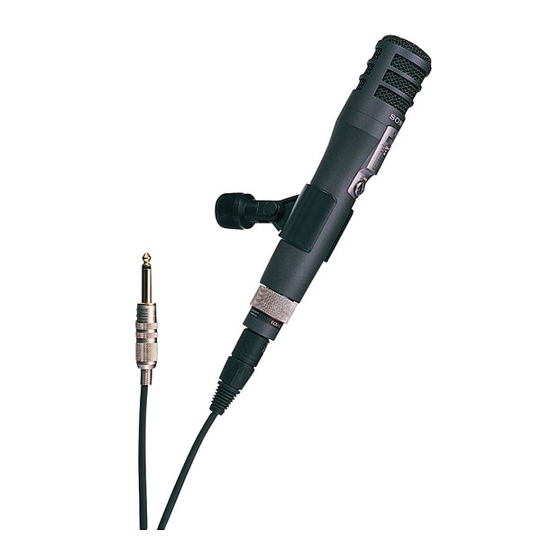
C-357
Canadian Model
AEP Model
SPECIFICATIONS
CONDENSER MICROPHONE
US Model
SECTION 1
This section is extracted from
instruction manual.
GENERAL
Notes on chip component replacement
• Never reuse a disconnected chip component.
• Notice that the minus side of a tantalum capacitor may be
damaged by heat.
— 2 —
Advertisement

Related Manuals for Sony C-357


Summary of Contents for Sony C-357
- Page 1 C-357 SECTION 1 This section is extracted from instruction manual. GENERAL SERVICE MANUAL US Model Canadian Model Ver 1.0 1999. 02 AEP Model SPECIFICATIONS CONDENSER MICROPHONE Notes on chip component replacement • Never reuse a disconnected chip component. • Notice that the minus side of a tantalum capacitor may be damaged by heat.
- Page 2 SECTION 2 DISASSEMBLY Note : Follow the disassembly procedure in the numerical order given. 2-3. AMP BOARD 2-1. CASE ASSY, MICROPHONE 7 Two screws (+PTPWH 2 × 5) 1 Remove soldering 3 Remove soldering 5 Remove three solderings and remove the three harnesses. 6 Remove the two solderings and remove the harness.
- Page 3 C-357 SECTION 3 DIAGRAMS 3-1. PRINTED WIRING BOARD 3-2. SCHAMITIC DIAGRAM (DIRECTIVITY) OMNI AMP BOARD AMP BOARD (SIDE A) (SIDE B) (DIRECTIVITY) OMNI MIC1 TYPE MIC1 POWER/LOW-CUT CAPSULE 0.0012 CAPSULE 999.99M 100K BATTERY 999.99M CHECK 19.6 INDICATOR 24.0 POWER 46.4 /LOW-CUT D-D CONV.
-
Page 4: Exploded Views
C-357 SECTION 4 SECTION 5 EXPLODED VIEWS ELECTRICAL PARTS LIST NOTE: NOTE: • -XX, -X mean standardized parts, so they may • The mechanical parts with no reference number • Due to standardization, replacements in the • CAPACITORS: • COILS When indicating parts by reference number, have some differences from the original one.