
Related Manuals for GE GCG1500BB


Summary of Contents for GE GCG1500BB
- Page 1 GE Consumer & Industrial Technical Service Guide JULY 2006 15-in. Built-In Compactors GCG1500BB GCG1500WW GCG1580SS GCG1700II ZCGS150SS ZCGP150II 31-9143 GE Appliances General Electric Company Louisville, Kentucky 40225...
- Page 2 If grounding wires, screws, straps, clips, nuts, or washers used to complete a path to ground are removed for service, they must be returned to their original position and properly fastened. GE Consumer & Industrial Technical Service Guide Copyright © 2006 All rights reserved.
-
Page 3: Table Of Contents
Table of Contents Built-In Compactor Components ..........................13 Care and Cleaning of the Built-In Compactor ....................10 Chain ....................................... 22 Component Locator Views ............................11 Control Panel ..................................13 Control Features ................................7 Diagnostics and Service Information ........................23 Directional Switch ................................14 Features .................................... -
Page 4: Features
Features – 4 –... -
Page 5: Installation Requirements
WARNING: DO NOT OPERATE FREE-STANDING. This OFF knob prevents unwanted use. With 2300 lbs. compactor is designed as a built-in appliance only. maximum compacting force, the GE 15-in. built-In Weight on the compactor drawer could cause the compactor reduces trash volume by 75%. -
Page 6: Nomenclature
Cabinetry Panel Door S = Stainless P = Panel Model Year Designator Width 150 = 15 inch GE Profile G C G 1 5 0 0 L S S Brand G = General Electric Exterior Color Product Type BB = Black... -
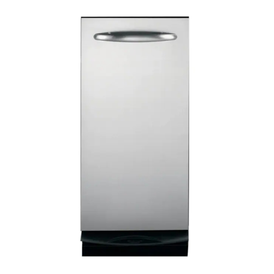
Page 7: Control Features
Control Features Throughout this manual, features and appearance may vary from your model. GE Profile Model Shown Features 1. DRAWER HANDLE 5. ON-OFF KNOB 6. DRAWER SAFETY SWITCH 2. DOOR PANEL 3. FOOT PEDAL DRAWER OPENER AND 7. MODEL AND SERIAL NUMBER LABEL COMPACTOR ACTIVATION 8. -
Page 8: Using The Built-In Compactor
Using the Built-In Compactor What It Does and How It Works trash bags included with your compactor. These bags are available from your dealer or Factory Your compactor reduces household trash to as little Service Center. Ask for catalog number WC60X5017. as one-fourth of its original volume. - Page 9 Compacting To stop the compactor: To start the compactor: The compactor may be stopped at any time. 1. Turn the knob to ON. 1. Attempting to open the drawer while the ram is moving will stop the ram. The safety switch will 2.
-
Page 10: Care And Cleaning Of The Built-In Compactor
Bryte or a similar product using a clean, soft cloth. ® use a vacuum designed Cerama Bryte is available from GE Parts by calling to pick up liquid. 800.626.2002 (U.S.) or 800.661.1616 (Canada). 4. Wash, rinse and dry the To clean the drawer interior: inside. -
Page 11: Component Locator Views
Component Locator Views 15-in. Built-In Compactor (Continued next page) – 11 –... - Page 12 Power Screw Assembly Ram Assembly Chain Drive Gear Shaft Plate Actuator Bracket Top Limit-Directional Switch Bottom View (bottom pan removed) Top View (top cover removed) Motor Rear View (rear motor cover removed) – 12 –...
-
Page 13: Built-In Compactor Components
Built-In Compactor Components Control Panel Switch Bracket To remove the control panel: To remove the switch bracket: 1. Open the compactor drawer. Turn the knob to Disconnect power. the off position and remove it by pulling straight Remove the control panel. (See Control Panel out. -
Page 14: Directional Switch
Caution: Ensure the switch bracket is installed Top Limit Switch with the switch arms resting in front of the switch actuator bracket. Damage to the top limit and/or Note: Disconnect power to the compactor before directional switch will occur if the switch arms are accessing the top limit switch. -
Page 15: Start Switch
Start Switch Tilt Switch Note: Disconnect power to the compactor before Note: Disconnect power to the compactor before accessing the start switch. accessing the tilt switch. The start switch is located in the front of the The tilt switch is located in the front of the compactor on the lower right side. -
Page 16: Tilt Switch (Drawer)
Tilt Switch (Drawer) Top Cover Panel Note: Disconnect power to the compactor before Note: To access the top cover panel, the compactor accessing the tilt switch (drawer). must be removed from installation. The tilt switch (drawer) is located inside the cabinet The top cover panel is attached to the frame with 6 on the right side wall. -
Page 17: Motor Assembly
Remove the 2 Phillips-head screws and the side Motor Assembly track shield from the motor cover. Note: To access the motor assembly, the compactor Disconnect the motor wire harness and the must be removed from installation. black neutral wire from the motor (protector). Motor Motor Wire Harness Neutral Wire... - Page 18 Remove the four 3/8-in. bolts that attach the To replace the motor: motor assembly to the frame. Place the motor assembly on a protected Slide the motor assembly towards the front to surface. loosen the chain. Mark the position of the motor on the shaft plate.
-
Page 19: Ram Assembly
Disconnect power. Ram Assembly Remove the switch bracket. (See Switch Bracket Note: To access the ram assembly, the compactor must be removed from installation. Lift and remove the ram assembly from the top of the power screws. To remove the ram assembly: Remove the top cover. - Page 20 Connect power and check operation of ram Power Screw Nut before installing top cover. A power screw nut is attached to the bottom of each side of the ram. It is necessary to use a small Ram Slides flat-blade screwdriver to remove the retaining clip and pin that hold each power screw nut to the ram.
-
Page 21: Power Screw Assembly
Pull up the stopper and stopper cap and remove Power Screw Assembly both from the power screw assembly. Note: To access the power screw assembly, the compactor must be removed from installation. Note: The following describes the procedure to remove the left side power screw assembly. The procedure to remove the right side power screw assembly is identical. -
Page 22: Chain
Loosen the four 3/8-in. bolts that attach the Chain motor assembly to the frame. (See Motor Assembly Note: To access the chain, the compactor must be removed from installation. Slide the motor assembly towards the front to loosen the chain. To remove the chain: Using a flat-blade screwdriver, pry off the clip Remove the ram assembly. -
Page 23: Diagnostics And Service Information
Diagnostics and Service Information Tilt Switch (drawer) Electrical Troubleshooting Guide Remove the wires from the tilt switch (drawer) and PROBLEM CAUSE connect an ohmmeter between the two terminals. Unit Dead Not plugged in No power to the outlet Refer to the wire schematic for the position of the ... - Page 24 Jammed Ram “Not Compacting” Complaints 1. Check for 120 Volts at the outlet. Low Voltage - Check supply voltage with the ram compacting trash. At 120 volts ram 2. If drawer is open, push in on the drawer. force is approximately 2300 lbs. At voltage lower than 120 volts ram force is reduced.
-
Page 25: Schematic
Schematic WARNING: Disconnect electrical power before servicing. Caution: Label all wires prior to disconnection. Wiring errors can cause improper and dangerous operation. Verify operation after servicing. TILT SWITCH (DRA WER) BLACK TILT SWITCH ORANGE YELLOW CW START ON-OFF SWITCH BROWN CC W STA RT NC 2 NO 2... -
Page 26: Warranty
Warranty – 26 –...