Table of Contents
Advertisement
For detailed troubleshooting information,
refer to the "Service Hints/Technical Guide" document posted on the TSN website.
For information about this model, type TC-P2012 in the model box under "Direct Search".
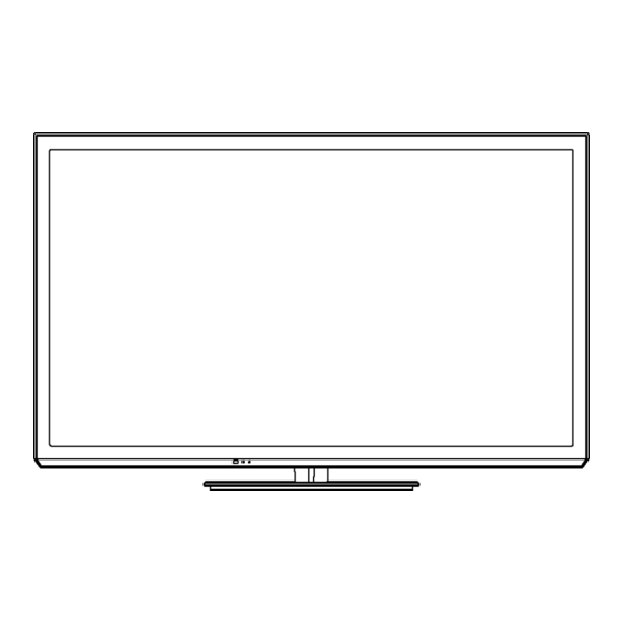
42 inch Class 720p Plasma HDTV
TC-P42XT50
Model No.
GPF15DU Chassis
© Panasonic Corporation 2012.
Unauthorized copying and distribution is a violation
of law.
ORDER NO.MTNC120307CE
B34 Canada: B62
Advertisement
Table of Contents

Related Manuals for Panasonic TC-P42XT50


Summary of Contents for Panasonic TC-P42XT50
- Page 1 For detailed troubleshooting information, refer to the "Service Hints/Technical Guide" document posted on the TSN website. For information about this model, type TC-P2012 in the model box under "Direct Search". © Panasonic Corporation 2012. Unauthorized copying and distribution is a violation of law.
-
Page 2: Table Of Contents
TABLE OF CONTENTS PAGE PAGE 1 Safety Precautions -----------------------------------------------3 1.1. General Guidelines ----------------------------------------3 2 Warning --------------------------------------------------------------4 2.1. Prevention of Electrostatic Discharge (ESD) to Electrostatically Sensitive (ES) Devices ----------4 2.2. About lead free solder (PbF) ----------------------------5 3 Service Navigation------------------------------------------------6 3.1. PCB Layout --------------------------------------------------6 3.2. -
Page 3: Safety Precautions
1 Safety Precautions 1.1. General Guidelines 1. When conducting repairs and servicing, do not attempt to modify the equipment, its parts or its materials. 2. When wiring units (with cables, flexible cables or lead wires) are supplied as repair parts and only one wire or some of the wires have been broken or disconnected, do not attempt to repair or re-wire the units. -
Page 4: Warning
2 Warning 2.1. Prevention of Electrostatic Discharge (ESD) to Electrostatically Sensitive (ES) Devices Some semiconductor (solid state) devices can be damaged easily by static electricity. Such components commonly are called Electrostatically Sensitive (ES) Devices. Examples of typical ES devices are integrated circuits and some field-effect transistors and semiconductor [chip] components. -
Page 5: About Lead Free Solder (Pbf)
2.2. About lead free solder (PbF) Note: Lead is listed as (Pb) in the periodic table of elements. In the information below, Pb will refer to Lead solder, and PbF will refer to Lead Free Solder. The Lead Free Solder used in our manufacturing process and discussed below is (Sn+Ag+Cu). That is Tin (Sn), Silver (Ag) and Copper (Cu) although other types are available. -
Page 6: Service Navigation
3 Service Navigation 3.1. PCB Layout Board Name Function Power Supply, Sustain Drive Non serviceable. PSS-Board should be exchanged for service. Main AV input, processing Remote receiver, Power LED, C.A.T.S. sensor Data Driver (Lower Right) Data Driver (Lower Left) Scan Drive... -
Page 7: Applicable Signals
3.2. Applicable signals * Mark: Applicable input signal for Component (Y, P ), HDMI horizontal frequency (kHz) vertical frequency (Hz) 525 (480) / 60i 15.73 59.94 525 (480) /60p 31.47 59.94 750 (720) /60p 45.00 59.94 1,125 (1,080) /60i 33.75 59.94 1,125 (1,080) /60p 67.43... -
Page 8: Specifications
TV Set only 37.5 lb. (17.0 kg) NET Bluetooth Standard Compliance ® Bluetooth Frequency Range 2.402GHz~2.480GHz • Use Panasonic 3D Eyewear supporting Bluetooth wireless technology. Note Design and Specifications are subject to change without notice. Mass and Dimensions shown are approximate. -
Page 9: Technical Descriptions
5 Technical Descriptions 5.1. Specification of KEY for DTCP-IP, WMDRM and Widevine 5.1.1. General information: 1. EEPROM (IC8902) for spare parts has the seed of KEY for each DTCP-IP for DLNA, WMDRM for Netflix and Widevine for CinemaNow. 2. The final KEY data will be generated by Peaks IC (IC8000) when SELF CHECK was done and are stored in both Peaks IC (IC8000) and EEPROM (IC8902). -
Page 10: Service Mode
6 Service Mode 6.1. How to enter into Service Mode 6.1.1. Purpose After exchange parts, check and adjust the contents of adjustment mode. While pressing [VOLUME ( - )] button of the main unit, press [INFO] button of the remote control three times within 2 seconds Note: Service Mode can not be entered when 3D signal input. -
Page 11: Contents Of Adjustment Mode
Contents of adjustment mode 6.1.4. • Value is shown as a hexadecimal number. • Preset value differs depending on models. • After entering the adjustment mode, take note of the value in each item before starting adjustment. Main item Sub item Sample Data Remark ADJUST... -
Page 12: Option - Mirror
6.2. Option - Mirror Picture can be reversed left and right or up and down. 00 : Default (Normal picture is displayed) 01 : Picture is reversed left and right. 02 : Picture is reversed up and down. Hint : If the defective symptom (e.g. Vertical bar or Horizontal bar) is moved by selection of this mirror, the possible cause is in A-board. -
Page 13: Hotel Mode
6.4. Hotel mode 1. Purpose Restrict a function for hotels. Item Function 2. Access command to the Hotel mode setup menu Mode Select hotel mode On/Off In order to display the Hotel mode setup menu: Input Select input signal modes. While pressing [VOLUME (-)] button of the main unit, Set the input, when each time power is switched on. -
Page 14: Data Copy By Sd Card
6.5. Data Copy by SD Card 6.5.1. Purpose (a) Board replacement (Copy the data when exchanging A-board): When exchanging A-board, the data in original A-board can be copied to SD card and then copy to new A-board. (b) Hotel (Copy the data when installing a number of units in hotel or any facility): When installing a number of units in hotel or any facility, the data in master TV can be copied to SD card and then copy to other TVs. - Page 15 6.5.3. Data copy from TV set to SD Card 1. Turn on the TV set. 2. Insert SD card with a startup file (pwd file) to SD slot. On-screen Display will be appeared according to the startup file automatically. 3. Input a following password for (a) or (b) by using remote control. (a) For Board replacement : 2770 (b) For Hotel : 4850 Data will be copied from TV set to SD card.
- Page 16 6.5.4. Data copy from SD Card to TV set 1. Turn on the TV set. 2. Insert SD card with Data to SD slot. On-screen Display will be appeared according to the Data folder automatically. 3. Input a following password for (a) or (b) by using remote control. (a) For Board replacement : 2771 (b) For Hotel : 4851 Data will be copied from SD card to TV set.
-
Page 17: Troubleshooting Guide
7 Troubleshooting Guide For detailed troubleshooting information, refer to the "Service Hints/Technical Guide" document posted on the TSN website. For information about this model, type TC-P2012 in the model box under "Direct Search". -
Page 18: Disassembly And Assembly Instructions
8 Disassembly and Assembly Instructions 8.1. Disassembly Flow Chart for the Unit This is a disassembly chart. When assembling, perform this chart conversely. -
Page 19: Disassembly Procedure For The Unit
8.2. Disassembly Procedure for the Unit 8.2.1. Remove the Pedestal stand 8.2.4. Remove the Bluetooth module 1. Remove the Plasma panel section from the servicing 1. Remove the screw (×1 ) and remove the Bluetooth stand and lay on a flat surface such as a table (covered module. -
Page 20: Remove The Speakers
8.2.7. Remove the PSS-Board 8.2.9. Remove the Speakers Caution: 1. Unlock the cable clampers and the tapes to free the To remove P.C.B. wait 1 minute after power was off for cables. discharge from electrolysis capacitors. 2. Disconnect the Speaker terminal. 1. - Page 21 8.2.11. Remove the BT connector clamper 8.2.13. Remove the M8 nut metals 1. Unlock the cable clampers and the tapes to free the 1. Remove the screw (×1 each) and remove the M8 nut cables. metals. 2. Remove the claws (×2 ) and remove the BT cable.
-
Page 22: Replace The Plasma Panel
8.2.19. Replace the Plasma panel 3. Remove the Cabinet assy from the Plasma panel section. Caution: Place the Plasma panel on a flat surface of a table (covered by a soft cloth) and a cushion. 8.2.16. Remove the Contact metal bottom 1. -
Page 23: Measurements And Adjustments
9 Measurements and Adjustments 9.1. Adjustment 9.1.1. Vsus selection Caution: When Plasma panel or A-board is replaced, Vsus should be set to LOW or HIGH. Procedure 1. Go into main item [VSUS] in Service Mode. LOW or HIGH will be displayed. 2. -
Page 24: White Balance Adjustment
9.1.2. White balance adjustment Name of measuring instrument Remarks Color analyzer (Minolta CS-1000 or equivalent) Procedure Remarks 1. Enter the Service mode. 2. Receive the Analog-RF (except for no signal) or set CVBS/YUV/HDMI (no signal is available). 3. Select [WB-ADJ] by using [1] and [2] key in the remote controller. 4. -
Page 25: Block Diagram
10 Block Diagram 10.1. Main Block Diagram MAIN AV INPUT,PROCESSING HDMI1-2 (HDMI2) ETHERNET DATA TMDS DATA ETHERPHY ETHERNET LAN CON I/F HDMI I/F USB I/F USB_1-2 IFD_OUT TUNER TUNER I/F BLUETOOTH PEAKS-LD4 SD CARD DATA V/Y/PB/PR SD CARD VIDEO/ V/YPbPr/RGB/YC SD CARD I/F COMPONENT ARC_OUT... -
Page 26: Block (1/4) Diagram
10.2. Block (1/4) Diagram JK8600 SPEAKER_L SPEAKER_R BLUETOOTH SD CARD D3201 DIGITAL JK8602 JK8601 JK4700 JK4701 AUDIO TU6706 ETHERNET USB1 USB2 MAIN AV INPUT,PROCESSING ANT IN HDMI1 HDMI2 TUNER IC8650 DMD_ ETHERPHY IIC0 BT3.3V IC4900 X8651 AUDIO AMP 25MHz SOUND15V WOL3.3V SUB5V SUB3.3V... -
Page 27: Block (2/4) Diagram
10.3. Block (2/4) Diagram MAIN AV INPUT,PROCESSING IC9300 PD6H VIDEO DATA PLASMA AI VIDEO DATA LVDS DATA H/V Sync Control VIDEO DATA Sub Filed Processor VIDEO DATA IC9803 P+1.2V DCDC15V P+1.2V IIC0 DATA DRIVER CONTROL +1.2V 1.2V P+3.3V IC9005 P+2.5V DCDCEN D_UHZ P+3.3V... -
Page 28: Block (3/4) Diagram
10.4. Block (3/4) Diagram PSS POWER SUPPLY,SUSTAIN DRIVE Vsus Vsus COLD COLD FREQUENCY RANGE (110Khz) FREQUENCY RANGE SUSOUT (120Khz) F201 AC CORD PLASMA B+(390V) PANEL EMI FILTER Vsus SUSTAIN CONTROL DC/DC SS-BLOCK P+5V HB LLC PANEL 15Vc SUSTAIN ELECTRODE STB5V OCP/OVP UVP/OVP FPC PROTECTOR... -
Page 29: Block (4/4) Diagram
10.5. Block (4/4) Diagram SCAN DRIVE Reference Voltage Vsus Lo : 189V TPVSUS Vsus Hi : 194V IC16784,85 Reference Voltage Vsus Vad = 205 PC16897 IPD CIRCUIT TPVAD IC16600 T16471 VAD GEN. IC16603 D16618 SHUNT REG CERS BUFFER NCPH Q16601 IC16501 Q16401 BUFFER... -
Page 31: Wiring Connection Diagram
11 Wiring Connection Diagram 11.1. Caution statement. Caution: Please confirm that all flexible cables are assembled correctly. Also make sure that they are locked in the connectors. Verify by giving the flexible cables a very slight pull. 11.2. Wiring (1) -
Page 32: Wiring (2)
11.3. Wiring (2) -
Page 33: Wiring (3)
11.4. Wiring (3) -
Page 34: Wiring (4)
11.5. Wiring (4) - Page 35 Model No. : TC-P42XT50 Schematic Diagram Note...
- Page 36 Model No. : TC-P42XT50 Replacement Parts List Note...
- Page 37 Model No. : TC-P42XT50 A-Board (1/13)
- Page 38 Model No. : TC-P42XT50 A-Board (2/13)
- Page 39 Model No. : TC-P42XT50 A-Board (3/13)
- Page 40 Model No. : TC-P42XT50 A-Board (4/13)
- Page 41 Model No. : TC-P42XT50 A-Board (5/13)
- Page 42 Model No. : TC-P42XT50 A-Board (6/13) and K-Board...
- Page 43 Model No. : TC-P42XT50 A-Board (7/13)
- Page 44 Model No. : TC-P42XT50 A-Board (8/13) S-10...
- Page 45 Model No. : TC-P42XT50 A-Board (9/13) S-11...
- Page 46 Model No. : TC-P42XT50 A-Board (10/13) S-12...
- Page 47 Model No. : TC-P42XT50 A-Board (11/13) S-13...
- Page 48 Model No. : TC-P42XT50 A-Board (12/13) S-14...
- Page 49 Model No. : TC-P42XT50 A-Board (13/13) S-15...
- Page 50 Model No. : TC-P42XT50 C1-Board S-16...
- Page 51 Model No. : TC-P42XT50 C2-Board S-17...
- Page 52 Model No. : TC-P42XT50 SN-Board (1/4) S-18...
- Page 53 Model No. : TC-P42XT50 SN-Board (2/4) S-19...
- Page 54 Model No. : TC-P42XT50 SN-Board (3/4) S-20...
- Page 55 Model No. : TC-P42XT50 SN-Board (4/4) S-21...
- Page 56 Model No. : TC-P42XT50 A-Board (Foil side) S-22...
- Page 57 Model No. : TC-P42XT50 A-Board (Component side) S-23...
- Page 58 Model No. : TC-P42XT50 K-Board S-24...
- Page 59 Model No. : TC-P42XT50 C1-Board S-25...
- Page 60 Model No. : TC-P42XT50 C2-Board S-26...
- Page 61 Model No. : TC-P42XT50 SN-Board S-27...
- Page 62 Model No. : TC-P42XT50 Parts List Ref. Safety Part No. Part Name & Description Q'ty Remarks TXN/A1RJUUS CIRCUIT BOARD A 1 (RTL)PAVCA N0AE6JK00005 CIRCUIT BOARD PSS 1 PAVCA TXNC11RJUU CIRCUIT BOARD C1 1 (RTL)PAVCA TXNC21RJUU CIRCUIT BOARD C2 1 (RTL)PAVCA...
- Page 63 Model No. : TC-P42XT50 Parts List Ref. Safety Part No. Part Name & Description Q'ty Remarks C5011 F1G1C104A077 C 0.1UF 16V C5012 EEEHB1C101UP C 100PF, J, 16V C5013 F1G1A105A047 C 1UF 10V C5014 F1G1A105A047 C 1UF 10V C5015 F1G1A105A047 C 1UF 10V...
- Page 64 Model No. : TC-P42XT50 Parts List Ref. Safety Part No. Part Name & Description Q'ty Remarks C8207 F1J1A106A087 C 10UF, 10V C8208 F1G1C104A077 C 0.1UF 16V C8210 F1G1C104A077 C 0.1UF 16V C8212 F1G1C104A077 C 0.1UF 16V C8215 F1G1C104A077 C 0.1UF 16V...
- Page 65 Model No. : TC-P42XT50 Parts List Ref. Safety Part No. Part Name & Description Q'ty Remarks C8737 F1G1C104A077 C 0.1UF 16V C8738 F1G1H222A830 C 2200PF, 50V 1 PAVCA C8739 F1G1E1030005 C 0.01UF 25V C8749 F1G1A105A047 C 1UF 10V C8750 F1G1A105A047...
- Page 66 Model No. : TC-P42XT50 Parts List Ref. Safety Part No. Part Name & Description Q'ty Remarks C14924 F1L2E104A028 C 0.10UF, 250V C14925 F1L2E104A028 C 0.10UF, 250V C14927 F1K2J2210003 C 220PF, 630V 1 PAVCA C14928 F1K2J2210003 C 220PF, 630V 1 PAVCA...
- Page 67 Model No. : TC-P42XT50 Parts List Ref. Safety Part No. Part Name & Description Q'ty Remarks C16723 F1K1E475A134 C 4.7UF 25V C16724 F1K1E475A134 C 4.7UF 25V C16725 F1K1E475A134 C 4.7UF 25V C16727 F1K2J331A042 C 330PF, 630V 1 PAVCA C16728 F1K2J331A042...
- Page 68 Model No. : TC-P42XT50 Parts List Ref. Safety Part No. Part Name & Description Q'ty Remarks K1MY55B00002 55P CONNECTOR 1 PAVCA CN0100 K1KA14A00248 14P CONNECTOR D3021 DZ2J140M0L ZENER DIODE D3022 DZ2J140M0L ZENER DIODE D3023 DZ2J140M0L ZENER DIODE D3024 DZ2J140M0L ZENER DIODE...
- Page 69 Model No. : TC-P42XT50 Parts List Ref. Safety Part No. Part Name & Description Q'ty Remarks D16668 DA3X103E0L DIODE 1 PAVCA D16673 B0ECHR000004 DIODE D16674 B0ECHR000004 DIODE D16685 DA2J10100L DIODE D16686 DA2J10100L DIODE D16711 B0ECHR000004 DIODE D16712 B0ECHR000004 DIODE D16713 B0ECHS000002...
- Page 70 Model No. : TC-P42XT50 Parts List Ref. Safety Part No. Part Name & Description Q'ty Remarks IC16600 C1ZBZ0004559 1 PAVCA IC16603 C0JBAA000344 IC16725 C1ZBZ0004715 1 PAVCA IC16784 MIP3910MSSCF IC16785 C0DBZYY00532 1 PAVCA IC16786 MIP3910MSSCF IC16787 C0DBZYY00532 1 PAVCA IC16795 C0CBALC00012...
- Page 71 Model No. : TC-P42XT50 Parts List Ref. Safety Part No. Part Name & Description Q'ty Remarks PC16461 B3PBE0000065 1 PAVCA PC16462 B3PBE0000060 PC16463 B3PBE0000060 PC16480 B3PBA0000611 1 PAVCA PC16603 B3PBA0000611 1 PAVCA PC16685 B3PBA0000625 1 PAVCA PC16723 B3PBA0000611 1 PAVCA...
- Page 72 Model No. : TC-P42XT50 Parts List Ref. Safety Part No. Part Name & Description Q'ty Remarks R2012 D0GA103JA023 M10KOHM, J.1/16 W R2034 D0GAR00J0005 M 0 OHM, 1/16W R2039 D0GA103JA023 M10KOHM, J.1/16 W R2041 D0GA433JA023 M 43KOHM,J,1/16W 1 PAVCA R2042 D0GA102JA023 M1KOHM, J.1/16 W...
- Page 73 Model No. : TC-P42XT50 Parts List Ref. Safety Part No. Part Name & Description Q'ty Remarks R5013 D0GA103JA023 M10KOHM, J.1/16 W R5932 D0GA103JA023 M10KOHM, J.1/16 W R6726 D0GA681JA023 M680 OHM, J,1/16W R6727 D0GA681JA023 M680 OHM, J,1/16W R6731 D0GA103JA023 M10KOHM, J.1/16 W...
- Page 74 Model No. : TC-P42XT50 Parts List Ref. Safety Part No. Part Name & Description Q'ty Remarks R8638 D0GA272JA023 M 2.7KOHM, J.1/16W R8639 D0GA103JA023 M10KOHM, J.1/16 W R8640 D0GA103JA023 M10KOHM, J.1/16 W R8641 D1HYR004A024 NETWORK RESISTER 1 PAVCA R8642 D1HYR004A024 NETWORK RESISTER...
- Page 75 Model No. : TC-P42XT50 Parts List Ref. Safety Part No. Part Name & Description Q'ty Remarks R8851 D0GA103JA023 M10KOHM, J.1/16 W R8853 D0GA103JA023 M10KOHM, J.1/16 W R8903 D1HY6808A012 NETWORK RESISTER 1 PAVCA R8906 D0GA472JA023 M 4.7KOHM, J,1/16W R8909 D0GA272JA023 M 2.7KOHM, J.1/16W...
- Page 76 Model No. : TC-P42XT50 Parts List Ref. Safety Part No. Part Name & Description Q'ty Remarks R14949 D0GD203JA052 M 20KOHM,J,1/8W R14950 D0GB103JA065 M 10K OHM J 1/10W R14960 D1H84704A041 NETWORK RESISTER 1 PAVCA R14961 D0GD271JA052 M 270 OHM,J,1/8W R14962 D0GD271JA052...
- Page 77 Model No. : TC-P42XT50 Parts List Ref. Safety Part No. Part Name & Description Q'ty Remarks R16621 D0GD561JA052 M 560 OHM,J,1/8W R16622 D0GD561JA052 M 560 OHM,J,1/8W R16658 D1BD9091A147 M 9.09KOHM,F.1/8W 1 PAVCA R16661 D0GD100JA059 M 10 OHM,J,1/4W R16663 D1BD9091A147 M 9.09KOHM,F.1/8W...
- Page 78 Model No. : TC-P42XT50 Parts List Ref. Safety Part No. Part Name & Description Q'ty Remarks R16939 D0GB472JA065 M 4.7KOHM, J,1/10W R16940 D0GB472JA065 M 4.7KOHM, J,1/10W R16945 D0GB471JA065 M 470 OHM,J,1/10W R16946 D0GB221JA065 M 220 OHM J 1/10W R16947 D0GB472JA065 M 4.7KOHM, J,1/10W...
- Page 79 Model No. : TC-P42XT50 Parts List Ref. Safety Part No. Part Name & Description Q'ty Remarks SN25 K1MY96BA0342 96P CONNECTOR SN26 K1MY96BA0342 96P CONNECTOR SN27 K1MY96BA0342 96P CONNECTOR SN28 K1MY96BA0342 96P CONNECTOR SN2810 B3JB00000116 T16471 G4DYA0000253 SWITCHING TRANS T16472 G4DYA0000252...
- Page 80 Model No. : TC-P42XT50 Exploded View 1 S-46...
- Page 81 Model No. : TC-P42XT50 Exploded View 2 S-47...
- Page 82 Model No. : TC-P42XT50 Accessories S-48...
- Page 83 Model No. : TC-P42XT50 Parts List Ref. Safety Part No. Part Name & Description Q'ty Remarks 10030-0061100 BATTERY COVER 1 PAVCA J0KG00000036 FERRITE CORE 2 PAVCA J0KG00000121 FERRITE CORE 2 PAVCA K2CG3YY00132 AC CORD(USA) Shielded 1 PAVCA MD42H15C1A PLASMA DISPLAY PANEL...